Transcription
Liquid vs Dry Type (VPI) Medium Voltage TransformersLooking at the history of the development of Dry Type Medium Voltage Transformers they becameincreasingly specified in the late 1950’s and early 1960’s due primarily to the improved insulationsystems (220 C) and acceptability of aluminum windings. Prior to the improvements in Dry TypeMedium Voltage Transformer design, indoor installations were very often either Mineral Oil Filled whichrequired a vault per NEC or PCB (Polychlorinated biphenyls) liquid filled transformers. The TSCA (ToxicSubstance Control Act) of 1976 prohibited the manufacture of PCB’s and also the phase out of existinguses (40 CFR Part 761). Due to a number of advantages Dry Type Medium Voltage Transformers becamethe preferred choice for most indoor and some outdoor installations.As a result of the development of the “less Flammable” Liquid filled transformers, a comprehensivecomparison between Liquid filled transformers and Dry Type Transformers seems to be in order.This article will discuss the comparison of Liquid Filled Transformers and Dry Type (VPI) Medium VoltageTransformers. The topics discussed are as follows:NEC (National Electric Code NFPA 70) Installation requirementsFactory Mutual Global clearance requirementsInspection and Testing prior to Energizing for the first timeMaintenance requirementsFan Cooling capacityBasic Impulse levelsContinuous overload capacityEfficiencyOperating Life ExpectancyDimensional ComparisonPricing and lead time Comparison10901 Commercial Street Richmond, IL 60071 800-336-5786 www.olsun.com
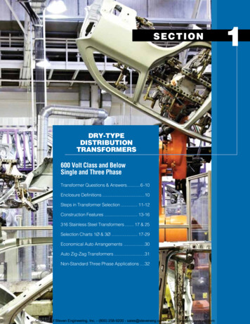
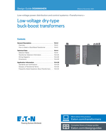
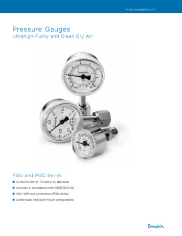
NEC Installation RequirementsThe installation requirements for Dry Type Medium Voltage Transformers per NEC (National ElectricCode NFPA 70 ) are summarized in Table I. Essentially there are very few restrictions regarding MediumVoltage Dry Type Transformers. However, proper clearances need to maintained around the Dry TypeTransformer for cooling purposes and maintenance.Indoor installations for Less Flammable liquid filled transformers (fire point not less than 300 C) haveseveral options. Refer to Table I. The most common option for 35 KV or less, Less Flammable liquid filledtransformers in TYPE I or TYPE II buildings requires a liquid confinement area and the installation mustcomply with the restrictions provided in the listing of the liquid.Outdoor installations for Less Flammable liquid filed transformers are permitted attached to, adjacentto, or on the roof of Type I and TYPE II Non combustible buildings as long as they comply with therestrictions of the listing of the liquid. If the installation is a combustible building or combustible materials are stored in the area then the installation would need to meet the requirements of Oilinsulated transformers mounted outdoors per NEC Article 450.27.Indoor installations of Oil insulated transformers would need to installed in a vault per NEC Part III ofArticle 450.For Outdoor installations of Oil insulated transformers if a fire hazard is present, Space separations, FireResistant barriers Automatic fire suppression systems or Enclosures for confinement of the oil in case ofa ruptured tank may be required depending on the degree of hazard.Factory Mutual Insurance CompanyFM Global publishes Property loss prevention recommendations. Property Loss Data sheets 5-4 coversthe loss prevention recommendations related to fire protection of all transformers for large and criticaldistribution, power and specialty transformers. Recommended Minimum separation recommendationsfor Liquid insulated transformers are listed in Table II. In addition, refer to FM Global Data sheets 5-4 forloss preventive recommendations for electrical protection, electrical testing, maintenance andoperation.FM Approvals ” Approval Standard for Less or Nonflammable Liquid insulated Transformers” ClassNumber 3990 includes the following installations requirements.Containment of the liquid is required for all indoor installations. For TYPE I and TYPE II Non combustiblebuildings the transformer needs to be mounted at least 3 ft. from building walls. For combustiblebuildings in addition to being mounted 3 ft. from walls an automatic fire suppression system must beprovided or the transformer must be located in a 3 hour fire rated vault.Outdoor installation of Less Flammable liquid filled transformers must be installed at least 3ft. fromwalls and 5 ft. from doors, fire escapes and windows. In addition, containment of the liquid is requiredfor transformers containing 660 gal. or more of liquid.
Table INEC ‐2014 Installation RequirementsType of TransformerDry Type ‐ over 112.5 KVA withinsulation system of 155 orgreater, completely enclosedexcept for ventilation openingsand rated less than 35KVIndoor InstallationArticle 450.21 (B) Exception No. 2No RestrictionsOutdoor InstallationArticle 450.22No RestrictionsLess Flammable liquid Filled with Article 450.23 (A) Indoor installations Article 450.23 (B) Outdoorfire point not less than 300 Care permitted if in accordance with installations are permittedone of the followingattached to, adjacent to,or onthe roof of buildings whereinstalled in accordance of (1) or(2)(1) In type I or Type II where all of the (1) For Type I and Type IIfollowing are met;(a)buildings installation shallTransformer is rated 35 KV or lesscomply with all restrictionsprovided for in the listing of the(b) no combustible materials areliquid *stored(c) A liquid confinement area isprovided(d) Installation complies with allrestrictions provided in the listing ofthe liquid(2) Automatic Fire Extinguishing(2) In accordance with 450.27 ‐system and liquid confine ment area Oil insulated Transformersproviding transformer is rated 35KV Installed Outdoorsor less(3) In accordance with 450.26 ‐ Oilinsulated Transformers installedIndoorsOil insulated TransformersArticle 450.26** Installed Indoors,Oil insulated transformers are to beinstalled in a vault per Part III ofArticle 450Article 450.27 Combustiblematerial, combustible buildingand parts of building, fireescapes, door openings andwindow openings shall besafeguarded from fires in oilinsulated transformers installedon roofs, attached to oradjacent to a building orcombutible material*NEC 450.23 (B) (1) Informational Note: Installations adjacent to combustible materialfire escapes, or door and window openings may require additional safeguards such as thoselisted in 450.27* *Refer to NEC Section 450.26 exceptions 1 thru 6References:National Electric Code ‐ NFPA ‐70 ‐ 2014
Per Approval listingFM Approved transformer orequivalentFM Approved Liquid in Non‐Approved transformerNon‐Approved transformer liquid515515253255025Minimum Horizontal Distance from Containment to Exposed Build ing WallCombustible Wall (ft.)2‐hour fire‐rated wall (ft.)Non‐combustible wall (ft.)**For other options refer to Factory Mutual Global Prevention Data Sheets 5‐4ReferencesFactory Mutual Global Property Loss Prevention Data Sheets 5‐4 500 5,000 10,000Fluid Volume (gal.)Recommended Minimun Separation for Outdoor Liquid‐insulated Transformers**Fluid or Transformer TypeTable II
Installation RequirementsMineral Oil filled transformersThe transformer must be mounted on a level pad and should not be tilted beyond two degreesfrom Horizontal. The ambient should not be below -20 C for Mineral Oil, - O C for RTemp and-10 C for FR3 . Special procedures are required when energizing below -20 C.Visually Inspect all seals, gaskets, gauges, bushing, etc. for liquid leaking. Leaks and/or improperlytightened gaskets or seals should be repaired prior to energizing the transformer.Determine if liquid level is correctCheck pressure. The transformer may have a positive or negative pressure which is acceptable. Zeropressure could indicate a gas leak and should be investigated. A leak test may need to be preformed.Recommended tests are insulation resistance (Megger test) and turns ratio testIn addition, Liquid samples should be taken per ASTM D923 and tested per ASTM D-877. If dielectricstrength is below acceptable level liquid should be filtered.Less Flammable Liquid filled TransformersSame recommended installation requirements as for Mineral Oil filled transformer. Recommended testsfor less flammable liquids include dielectric strength, moisture content and flash and fire points.Dry Type TransformersVisual inspection should be done to insure there has not been any damage to the internal componentsof the Dry Type transformerRecommended tests prior to energizing a Dry Type Transformer are Insulation resistance (megger test),turns ratio test and applied potential test. .References:Cooper Power S210-15-10 Substation Transformer Installation, Operation and Maintenance InstructionsHoward Industries 2.4.126 Rev 2 Three Phase Pad Mounted Distribution TransformersIEEE C57.106 Guide for Acceptance and Maintenance of Insulating Oil in EquipmentIEEE C57.93 Guide for installation of Liquid- Immersed Power TransformersIEEE C57.94 Recommended Practice for Installation, Application, Operation , and Maintenance of DryType General Purpose Distribution and Power Transformers
Recommended MaintenanceMineral Oil filled transformersInspect and tighten all bolted connections and check for leaks. Zero pressure could indicate a gas leakand should be investigatedRegularly inspect all gauges and liquid level. Check gaskets for deterioration and replace if necessaryLiquid samples should be taken periodically and tested per ASTM D-877. If dielectric strength is belowacceptable level liquid should be filtered.If spill should occur refer to applicable local, state and federal guidelinesLess Flammable Liquid filled TransformersSame recommended maintenance as for Mineral Oil filled transformer. Recommended tests for lessflammable liquids include dielectric strength, moisture content and flash and fire pointsDry Type TransformersVisual inspection should be done at regular intervals. Frequency of inspection depends on the operatingconditions.Inspect for any accumulation of dirt, contamination or loose connections. The transformer windings canbe cleaned using a vacuum cleaner, blower or compressed air.References:Cooper Power S210-15-10 Substation Transformer Installation, Operation and Maintenance InstructionsIEEE C57.106 Guide for Acceptance and Maintenance of Insulating Oil in EquipmentIEEE C57.94 Recommended Practice for Installation, Application, Operation , and Maintenance of DryType General Purpose Distribution and Power Transformers
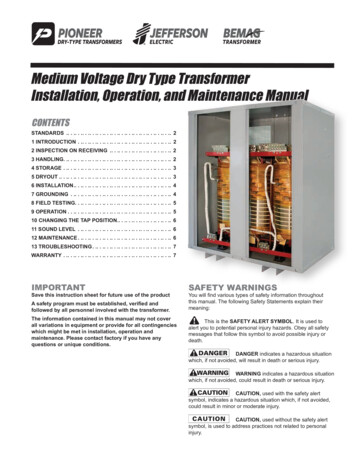
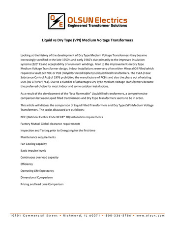
Fan Cooling CapacityThe increase in KVA capacity for Dry Type Transformers when provided with Fan Cooling (AA/FA) is33 1/3% for both Substation Type and Pad Mounted Dry Type Transformers. For Liquid filledTransformer the increase in capacity is only 15% for 750 KVA through 2000 KVA and only 25% for 2500KVA through 10,000 KVA. Fan cooling is not available for liquid filled Pad Mounted transformers. Referto Table III.Basic Impulse LevelsWe occasionally hear the statement liquid filled transformers have a higher BIL ratings than Dry TypeMedium Voltage Transformers. It is true the IEEE standard BIL levels for Medium Voltage Dry TypeTransformers are lower than the IEEE Standard BIL levels for Liquid Filled Transformers. However, theIEEE Standard C57.12.01 lists optional BIL levels for Medium Voltage Dry Types that are either equal toor exceed the BIL levels of Liquid Filled Transformers as listed in IEEE C57.12.00. Refer to Table V.Continuous Overload CapabilityWhen operated at rated load and with a rated winding temperature rise of 65 C liquid filledTransformers do not have any continuous overload capability without shortening its life expectancy.Likewise, Dry Type Medium Voltage Transformers (VPI) when operated at rated load and with a ratedwinding temperature rise of 150 C do not have any continuous overload capability without shorteningits life expectancy.However, a the Liquid filled transformer with a 120 insulation system and with a winding temperaturerise of 55 C can be overloaded by 12% of it’s KVA rating continuously without any shorting of it’s lifeexpectancy. Dry Type Transformers (VPI) with a 220 C insulation system and a winding temperature riseof 115 C can be overloaded continuously by 15% without any shortening of its life expectancy. With awinding temperature rise of 80 C rise and a 220 C insulation system a Dry Type Transformer (VPI) can beoverloaded continuously by 30% without any shorting of life expectancy. Refer to Table IV.For information on Short Time overload capability refer to IEEE C57.96 Guide for Loading Dry TypeTransformers and IEEE C57.91 Guide for Loading Mineral Oil Filled Transformers.EfficiencyFor the most part, Liquid Filled Transformers have a higher efficiency than Dry Type Medium VoltageTransformers. Due to the liquid cooling medium the core and coil of the liquid filled transformer issmaller than the equivalent Dry Type Medium Voltage Transformer which relies on Air for its coolingmedium. However, Dry Type Medium Voltage Transformers are very efficient electrical devices. Theminimum efficiencies required by DOE 10 CFR 431 Part K are listed in table VI for several KVA sizes.Although the efficiencies of the Medium Voltage Dry Types are slightly less than the correspondingLiquid Filled Transformers, the efficiency of the Dry Type Medium Voltage Transformers listed in table VIexceeds 99%.
Table IIIFan Cooling CapacityTransformer TypeDry Type ‐ substation typeDry Type ‐Pad MountLess Flammiable liquid ‐ substationtypeKVAFan Cooling Rating225 ‐ 10,000225 ‐ 500033 1/3 %33 1/3 %500 and below750 ‐ 20002500 ‐5000Less Flammiable liquid ‐ PadMountOil Filled ‐ substation typeThrough 5000500 and below501 ‐20002501 ‐ 10,000**Fan cooling Notavailable15%25%**Fan Cooling notavailableFan Cooling Notavailable15%25%Fan Cooling not available**Oil Filled ‐ Pad Mountthrough 5000** If fan cooling is provided the Pad Mount Transformer is no longer tamper resistantReferencesDry type per C57.50 and C57.51Liquid filled ‐ Cooper Power
or exceed the BIL levels of Liquid Filled Transformers as listed in IEEE C57.12.00. Refer to Table V. Continuous Overload Capability When operated at rated load and with a rated winding temperature rise of 65 C liquid filled Transformers do not have any continuous overload capability without shortening its life expectancy. Likewise, Dry Type Medium Voltage Transformers (VPI) when operated at .