Transcription
For the latest prices, please check AutomationDirect.com.1-800-633-0405Jefferson Electric Buck-Boost TransformersWhat is a buck-boosttransformer?Buck-boost transformers are designed tomaximize the performance and life of electrical equipment. They are typically used topower loads with specific voltage requirements that differ from the available linevoltage.The 2008 NEC Handbook Section 210.9provides the following definition for a buckboost transformer:A buck-boost transformer is classified as anautotransformer. A buck-boost transformerprovides a means of raising (boosting) orlowering (bucking) a supply line voltage bya small amount (usually no more than 20percent).A buck-boost is a transformer with twoprimary windings (H1-H2 and H3-H4) andtwo secondary windings (X1-X2 and X3-X4).Its primary and secondary windings areconnected so that the electrical characteristics are changed from a transformer that hasits primary and secondary windings isolatedfrom each other to one that has primary andsecondary windings connected to buck orboost the voltage as an autotransformer,correcting voltage by up to 20 percent.A single unit is used to boost or buck singlephase voltage. Two or three units are used toboost or buck three-phase voltage. An autotransformer requires little physical space, iseconomical, and above all, is efficient.A Buck-Boost transformer can have twomain applications:1. When connected as an autotransformer, you can buck (lower) or boost(raise) available line voltage anywherefrom 5 to 20 percent.2. When connected as an isolationtransformer, they can be used to stepdown supply power to low voltagecircuits at the nameplate rating listed.Standards/Approvals Built in accordance with UL1446,CAN/CSA - C22.2 No. 0 Agency Approval UL File #E4466Applications* Air conditioners Heating elements Motor applications (not motor control circuits per NFPA 79 9.1.1.1) 277 volt supply for lighting systemsFeatures Encapsulated with electrical grade resin Cores of high-quality electrical steel Aluminum/copper windings(see nameplate for product specific information) 60 Hz operation NEMA 3R-rated enclosures 135ºC temperature rise, 180ºC insulation class or 95ºC temperature rise,130ºC insulation class depending on kVA size Heat-cured ASA-61 gray powder coat finish Slotted mounting holes for quick and easy mounting Permanently affixed wiring diagram 10-year limited warranty (limited to mfg. defects) Single-phase encapsulated isolation transformer ratings 50VA to 2kVA Ambient temperature 0 - 25ºC (32 - 77ºF)(Per UL506, UL5085-1, 2 General Purpose Transformers)* Note: Buck-boost transformers do not compensate for fluctuating line voltages.They should only be used when line voltage is relatively 53
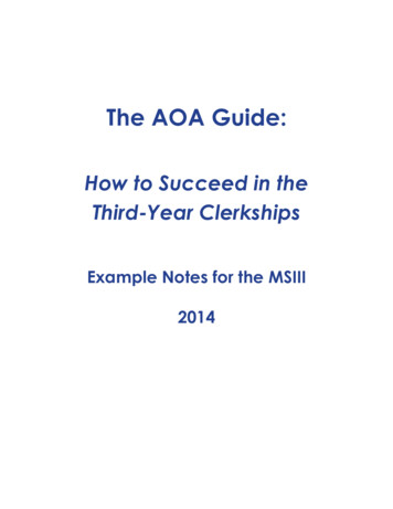
1-800-633-0405For the latest prices, please check AutomationDirect.com.Buck-Boost Single-phase ConnectionsNEC Handbook 2008 Exhibit 210.18 Typical single-phase connection diagrams for buck or boost transformersconnected as autotransformers to change 240 volts single-phase to 208 volts and vice versa.Boost (increase)HV High VoltageLV Low VoltageBuck (decrease)Courtesy of NFPA, from 2008 HandbookDifference between an autotransformerand an isolation transformerThe principal difference between an autotransformer and an isolation transformer is the separation of secondary windings. In an autotransformer, theinput (or primary) and the output (or secondary) are electrically connected,while in an isolation transformer they are completely separated, as shownto the right.Because autotransformers require fewer windings and smaller cores, theyare typically lighter and less costly than conventional isolation transformerswith the same ratings. Autotransformers do have some performance advantages too. They have increased power handling capability, flatter frequencyresponse, lower insertion loss and lower distortion than conventional transformers of similar size and cost. They do not, however, provide electricalisolation or stabilize fluctuating supply line voltages.Autotransformer (“Autoformers”)Autotransformers are best suited for applications where the line voltageneeds to be matched to a protected piece of equipment, for example toadapt a piece of equipment manufacturered in one country to operate inanother where the line voltage is slightly different. Autotransformers are asmart choice if the difference between the input and desired output voltagesis nominal.Isolation (or Insulating) F-54
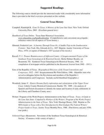
For the latest prices, please check AutomationDirect.com.1-800-633-0405Fusing Buck-Boost TransformersThe method for determining the correct size overcurrent protection for an autotransformer is covered inthe 2008 National Electric Code (NEC) 450.4 Autotransformers 600 Volts, Nominal, or Less.(A) Overcurrent Protection: Each autotransformer 600 volts, nominal, or less shall beprotected by an individual overcurrent device installed in series with each ungroundedinput conductor. Such overcurrent device shall be rated or set at not more than 125percent of the rated full-load input current of the autotransformer. Where this calculation does not correspond to a standard rating of a fuse or nonadjustable circuitbreaker and the rated input current is 9 amperes or more, the next higher standardrating described in 240.6 shall be permitted. An overcurrent device shall not beinstalled in series with the shunt winding (the winding common to both the input andthe output circuits) of the autotransformer between Points A and B as shown in Exhibit450.6 (below).Exhibit 450.6 provides an example of overcurrent protection for an autotransformer. It shows a two-winding,single-phase transformer connected to boost a 208-volt supply to 240 volts. The autotransformer isprovided with a two-pole disconnect switch with both overcurrent devices (OC-1a and OC-1b) located onthe supply sideof the autotransformer.Courtesy of NFPA, from 2008 5
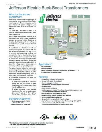
For the latest prices, please check AutomationDirect.com.1-800-633-0405Buck-Boost TransformerSelection InformationHow to select the proper transformerTo select the proper transformer for buck-boost applications, determine the following first:Line VoltageThe voltage that you want to buck (decrease) or boost (increase). This can be found by measuringthe supply line voltage with a voltmeter.Load VoltageThe voltage at which your equipment is designed to operate. This is listed on the nameplate ofthe load equipment.Load kVA or load AmpsYou do not need to know both. One is sufficient for selection purposes. This information usuallycan be found on the nameplate of the equipment that you want to operate.Supply Line and Equipment FrequenciesThe supply line frequency must be the same as the frequency of the equipment to be operated.This will be 60 Hz for buck-boost transformers.Number of PhasesSingle-phase or three-phase line and load should match because a transformer is not capable ofconverting single-phase to three-phase.The Type of Electrical ConfigurationDelta or Wye.How to use the selection chartson the following pagesExample:(Assume the following information)1. Find the appropriate single-phase, three-phase deltaor three-phase wye table.2. Read across the appropriate input/output voltagerows and find the nearest ratio of required loadvoltage to line voltage for the application desired.(High voltage (HV) and low voltage (LV) may beeither input or output voltage depending on thecircumstances.)3. Reading vertically down the column beginning withyour application voltage ratio, locate in one of thekVA rows a kVA capacity equal to or larger than yourload requirement.4. Now move left across the kVA row to locate theappropriate transformer catalog number for yourapplication.www.automationdirect.com1. A reasonably constant line voltage of 200 volts.2. A required equipment voltage of 236 volts.3. 1.6 kVA load capacity needed.4. Single-phase line and equipment.In the voltage rows, 208 is closest to our linevoltage of 200. The 236 high voltage meets ourrequirements.Reading vertically down this column, find 1.8 kVA, theclosest larger kVA to our required 1.6 load kVA.Moving left across this row, you will find thetransformer catalog number to be 416-1221-000.TransformerstTXF-56
For the latest prices, please check AutomationDirect.com.1-800-633-0405Buck-Boost Single-Phase Selection ChartSingle-Phase ConnectionPart NumberInput orOutputLV 83.0175.042.0167.092.022.083.0HV AmpsLV Amps416-1101-000HV AmpsLV Amps416-1111-000HV AmpsLV Amps416-1121-000HV AmpsLV Amps416-1131-000HV AmpsLV Amps416-1141-000HV AmpsLV Amps416-1151-000HV AmpsLV Amps416-1161-000HV AmpsLV Amps416-1171-000HV AmpsWiring DiagramInput orPart NumberOutputLV Amps416-1201-000HV AmpsLV Amps416-1211-000HV AmpsLV Amps416-1221-000HV AmpsLV Amps416-1231-000HV AmpsLV Amps416-1241-000HV AmpsLV Amps416-1251-000HV AmpsLV Amps416-1261-000HV AmpsLV Amps416-1271-000HV AmpsWiring ct.comTransformerstTXF-57
For the latest prices, please check AutomationDirect.com.1-800-633-0405Buck-Boost 3-Phase Open DeltaSelection ChartPlease note: Three-phase open delta connections require two transformers.Three-Phase Open Delta ConnectionPart NumberInput orOutputLVHVLV AmpskVA416-1100-000HV AmpsLV Amps416-1101-000kVAHV AmpsLV 3.16.92.52.65.25.52.9Part NumberInput orOutputLVHVLV AmpskVA416-1201-000HV AmpsLV Amps416-1211-000kVAHV AmpsLV 92.24.74.79.44.78.98.916.78.93.23.36.53.7HV Amps6.36.312.512.56.3HV Amps7.87.815.67.8LV Amps11.511.521.921.911.5LV Amps17.717.733.317.74.14.38.79.14.86.46.513.07.4HV Amps10.410.420.820.810.4HV Amps15.615.631.315.6LV Amps22.922.943.843.822.9LV 0HV Amps20.820.841.741.720.8HV Amps23.423.446.923.4LV Amps34.434.465.665.634.4LV 251-000kVA12.413.026.027.314.312.813.026.014.7HV Amps31.331.362.562.531.3HV Amps31.031.063.031.0LV Amps46.046.088.088.046.0LV AHV AmpsLV Amps416-1161-000kVAHV AmpsLV Amps416-1171-000kVAHV AmpsWiring Diagramwww.automationdirect.com416-1261-000kVAHV AmpsLV Amps416-1271-000kVAHV AmpsWiring DiagramTransformerstTXF-58
For the latest prices, please check AutomationDirect.com.1-800-633-0405Buck-Boost 3-Phase Wye Selection ChartPlease note: Three-phase wye delta connections require three transformers.Three-Phase Wye ConnectionPart 00416-1171-000Input orOutputLV AmpsHV AmpsLV AmpsHV AmpsLV AmpsHV AmpsLV AmpsHV AmpsLV AmpsHV AmpsLV AmpsHV AmpsLV AmpsHV AmpsLV AmpsHV AmpsLV AmpsHV AmpsWiring DiagramPart 00Input orOutputLV AmpsHV AmpsLV AmpsHV AmpsLV AmpsHV AmpsLV AmpsHV AmpsLV AmpsHV AmpsLV AmpsHV AmpsLV AmpsHV AmpsLV AmpsHV AmpsWiring 541.765.647
kVA 0.8 0.9 1.7 1.8 1.0 kVA 1.3 2.6 1.5 HV Amps 2.14.2 HV Amps 3.16.3 416-1101-000 LV Amps 4.68.8 416-1211-000 LV Amps Transformers. Transformers. Transformers. Automation Direct .