Transcription
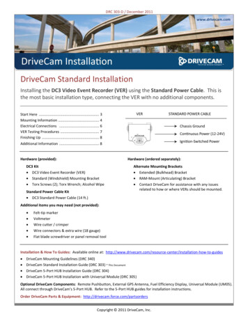
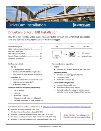
DRC 304-C / December 2011www.drivecam.comDriveCam 5-Port HUB InstallationHow to install the DC3 Video Event Recorder (VER) through the 5-Port HUB Connectorwith the optional GPS Antenna and/or Remote Trigger.Connection Diagram . 3VER & HUB Installation (Start Here) . 4Electrical Connections . 7GPS Antenna Installation . 10Remote Trigger Installation . 11Additional Information . 12Hardware (provided):Hardware (ordered separately):DC3 KitDC3 Video Event RecorderStandard (Windshield) Mounting BracketTorx Screws (2); Torx Wrench; Alcohol Wipe5-Port HUB KitDriveCam 5-Port HUB Connector with CoverHUB Interconnect Cable (14 ft.)HUB Power Cable (18 in.)Additional items you may need (not provided):Felt-tip markerVoltmeterWire cutter / crimperWire connectors & extra wire (18 gauge)Flat blade screwdriver or panel removal toolGPS KitDriveCam GPS Antenna with Attached Cable (10 ft.)Remote Trigger KitDriveCam Remote Trigger (Pushbutton)Pushbutton CollarPushbutton Cable (4½ ft.)Alternate Mounting BracketsExtended (Bulkhead) BracketRAM-Mount (Articulating) BracketContact DriveCam for assistance with any issuesrelated to how or where VERs should be mounted.Installation & How To Guides: Available online at: on-how-to-guidesDriveCam Mounting Guidelines (DRC 340)DriveCam Standard Installation Guide (DRC 303)DriveCam 5-Port HUB Installation Guide (DRC 304) * This DocumentDriveCam Fuel Efficiency Display (FED) Installation Guide (DRC 307)DriveCam 5-Port HUB Installation with Universal Module (DRC 305)Copyright 2011 DriveCam, Inc.Order DriveCam Parts & Equipment:http://drivecam.force.com/partsorders
Safety InformationRead and follow the instructions and precautions in this book when installing components.Refer to the vehicle service manual for proper installation and wiring of aftermarket devices.Failure to do so may result in property damage and/or personal injury.This equipment is suitable for use in Class I, Division 2, Groups A, B, C and D or non-hazardous locations only.WARNING – EXPLOSION HAZARD: Do not disconnect equipment unless power has been removed or the area is known to be non-hazardous.WARNING – EXPLOSION HAZARD: Substitution of components may impair suitability for Class I, Division 2.Regulatory InformationAdherence to Applicable Local, State and Federal Laws & RegulationsSome jurisdictions have adopted, or may in the future adopt, laws that prohibit objects from being mounted on a vehicle’s windshield. For example, California, Minnesota, New Jersey and Florida currentlyprohibit or limit the mounting of objects, including DriveCam event recorders, on windshields. You are responsible for complying with any such laws, and DriveCam does not accept responsibility for your failureto do so. If you plan to operate your vehicle in a jurisdiction where windshield mounting is prohibited, contact DriveCam for assistance with any issues related to how or where VERs should be mounted.USA Federal Communications Commission (FCC) NoticeThis device complies with part 15 of the FCC Rules. Operation is subject to the following two conditions: (1) This device may not cause harmful interference, and (2) this device must accept any interferencereceived, including interference that may cause undesired operation.Caution: Changes or modifications to this product not expressly approved by DriveCam Inc. could void the user's authority to operate this equipment.Note: This equipment has been tested and found to comply with the limits for a Class B digital device, pursuant to part 15 of the FCC Rules. These limits are designed to provide reasonable protection againstharmful interference in a residential installation. This equipment generates, uses, and can radiate radio frequency energy and, if not installed and used in accordance with the instructions, may cause harmfulinterference to radio communications. However, there is no guarantee that interference will not occur in a particular installation.The FCC with its action in ET Docket 96-8 has adopted a safety standard for human exposure to radio frequency (RF) electromagnetic energy emitted by FCC certified equipment. This device meets the HumanExposure limits found in OET Bulletin 65, 2001, and ANSI/IEEE C95.1, 1992. Proper operation of this radio according to the instructions found in this manual will result in exposure substantially below the FCC’srecommended limits.To comply with the FCC and ANSI C95.1 RF exposure limits, this device has been evaluated for compliance with FCC RF Exposure limits in the typical configuration. It is recommended that the antenna must notbe co-located or operating in conjunction with any other antenna or radio transmitter. During operation, the transmitter shall be separated at least 20cm (8 inches) from any human contact.Note: The radiated output power of this wireless device is far below the FCC radio frequency exposure limits. Nevertheless, this device should be used in such a manner that the potential for human contactduring normal operation is minimized.Canada – Industry Canada NoticeThis device complies with Industry Canada RSS-210 regulations. Operation is subject to the following two conditions: (1) This device may not cause harmful interference, and (2) this device must accept anyinterference received, including interference that may cause undesired operation.To prevent radio interference to the licensed service, this device must be operated indoors only and should be kept away from windows to provide maximum shielding.This Class B digital apparatus complies with Canadian ICES-003.” Cet appareil numérique de la classe B est conforme à la norme NMB- 003 du Canada.Exposure of Humans to RF FieldsThe installer of this radio equipment must ensure that the antenna is located or pointed such that it does not emit RF field in excess of Health Canada limits for the general population; consult Safety Code 6,obtainable from Health Canada’s website: www.hc-sc.gc.ca/rpbDeclaration of Conformity:EnglishHereby, DriveCam, Inc., declares that this DriveCamIII is in compliance with the essential requirements and other relevant provisions of Directive 1999/5/EC. The declaration of conformance is below.FinnishDriveCam, Inc. vakuuttaa täten että DriveCamIII tyyppinen laite on direktiivin 1999/5/EY oleellisten vaatimusten ja sitä koskevien direktiivin muiden ehtojen mukainen.DutchHierbij verklaart DriveCam, Inc. dat het toestel DriveCamIII in overeenstemming is met de essentiële eisen en de andere relevante bepalingen van richtlijn 1999/5/EGBij deze verklaart DriveCam, Inc. dat deze DriveCamIII voldoet aan de essentiële eisen en aan de overige relevante bepalingen van Richtlijn 1999/5/EC.FrenchPar la présente DriveCam, Inc. déclare que l'appareil DriveCamIII est conforme aux exigences essentielles et aux autres dispositions pertinentes de la directive 1999/5/CEPar la présente, DriveCam, Inc. déclare que ce DriveCamIII est conforme aux exigences essentielles et aux autres dispositions de la directive 1999/5/CE qui lui sont applicablesSwedishHärmed intygar DriveCam, Inc. att denna DriveCamIII står I överensstämmelse med de väsentliga egenskapskrav och övriga relevanta bestämmelser som framgår av direktiv 1999/5/EG.DanishUndertegnede DriveCam, Inc. erklærer herved, at følgende udstyr DriveCamIII overholder de væsentlige krav og øvrige relevante krav i direktiv 1999/5/EFGermanHiermit erklärt DriveCam, Inc., dass sich dieser/diese/dieses DriveCamIII in Übereinstimmung mit den grundlegenden Anforderungen und den anderen relevanten Vorschriften der Richtlinie 1999/5/EGbefindet". (BMWi)Hiermit erklärt DriveCam, Inc. die Übereinstimmung des Gerätes DriveCamIII mit den grundlegenden Anforderungen und den anderen relevanten Festlegungen der Richtlinie 1999/5/EG. (Wien)GreekΜΕ ΤΗΝ ΠΑΡΟΥΣΑ DriveCam, Inc. ΔΗΛΩΝΕΙ ΟΤΙ DriveCamIII ΣΥΜΜΟΡΦΩΝΕΤΑΙ ΠΡΟΣ ΤΙΣ ΟΥΣΙΩΔΕΙΣ ΑΠΑΙΤΗΣΕΙΣ ΚΑΙ ΤΙΣ ΛΟΙΠΕΣ ΣΧΕΤΙΚΕΣ ΔΙΑΤΑΞΕΙΣ ΤΗΣ ΟΔΗΓΙΑΣ 1999/5/ΕΚItalianCon la presente DriveCam, Inc. dichiara che questo DriveCamIII è conforme ai requisiti essenziali ed alle altre disposizioni pertinenti stabilite dalla direttiva 1999/5/CE.SpanishPor medio de la presente DriveCam, Inc. declara que el DriveCamIII cumple con los requisitos esenciales y cualesquiera otras disposiciones aplicables o exigibles de la Directiva 1999/5/CEPortuguese DriveCam, Inc. declara que este DriveCamIII está conforme com os requisitos essenciais e outras disposições da Directiva 1999/5/CE.Suppliers Declaration of ConformityWe DriveCam hereby declare that the product listed below, to which this Declaration of Conformity relates, is in conformity with the Standards and other Normative Documents listed below:Manufacturer’s Name & Address:DriveCam Inc. 8911 Balboa Ave., San Diego, CA 92123 USADeclares that the following product:Product Name: Video Event RecorderProduct Models: DC-3000-256-C, DC-3000-256-CA, DC-3000-256-CAP, DC-3000-256-CPThe product specified above carries the marking, by complying with the essential requirementsand provisions. Conformity is based upon the following standards:Safety: HERO certificationEMC & Radio:CFR Title 47 FCC Part 15, Subpart B, Class BIndustry Canada ICES‐003 Issue 4 (2004), Class BProduct Models: DC-3000-256-G, DC-3000-256-GA, DC-3000-256-GAP, DC-3000-256-GPThe product specified above carries the marking, by complying with the essential requirementsand provisions. Conformity is based upon the following standards:EMC & Radio:CFR Title 47 FCC Part 15, Subpart B, Class BIndustry Canada ICES‐003 Issue 4 (2004), Class BETSI EN 301 489-7 v1.3.1 (2005-11)ETSI EN 301 489-1 v1.8.1 (2008-04)EN 61000-4-3: 2006 A1: 2008EN 61000-4-6: 2007ISO 7637-2: 2004AS/NZS CISPR 22: 20062004/104/EC Automotive EMC Directive (ESA), Sections 6.5, 6.6, 6.8 and 6.9VCA, ATTESTATION WITH REGARD TO ANNEX I, Section 3.2.9 of 72/245/EECICASA TA-2009/1696Product Models: DC-3000-256-W, DC-3000-256-WAThe product specified above carries the marking, by complying with the essential requirementsand provisions. Conformity is based upon the following standardsEMC & Radio:ETSI EN 301 489-1 v1.8.1 (2008-04)FCC Part 15 Subpart BIndustry Canada ICES-003 Issue 4 February 2004CISPR 22: 2005 Information Technology EquipmentAS/NZS CISPR 22: 2006ETSI EN 301 489-17 (2002-08)Industry Canada RSS‐Gen Issue 1 (2005)Industry Canada RSS‐210 Issue 6 (2005)RTTE Directive 1999/5/ECETSI EN 301 489-1 v1.8.1 (2008-04)EN 61000-4-3: 2006 A1: 2008EN 61000-4-6: 2007ETSI EN 300 328 V1.6.1ISO 7637-2: 20042004/104/EC Automotive EMC Directive (ESA), Sections 6.5, 6.6, 6.8 and 6.9ISO 7637-2VCA ATTESTATION WITH REGARD TO ANNEX I, Section 3.2.9 of 72/245/EECICASA TA-2009/360CE Marking CE1177Manufacturer’s Contact:DriveCam Inc. 8911 Balboa Ave. San Diego, CA 92123 USAPhone Number: (858) 430‐4000 Fax Number: (858) 430‐4001DriveCam strives to provide the most up-to-date information, however, products and their applicability may change periodically and, therefore, DriveCammakes no representation as to the accuracy of the information provided herein and assumes no obligation to update such information.DriveCam 5-Port HUB Installation (304-C)2
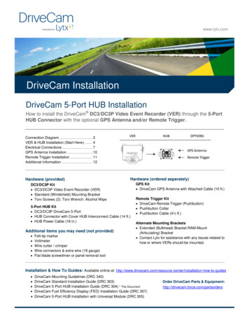
DriveCam 5-Port HUB Connection DiagramDC3 Video Event Recorder & 5-Port HUB (Basic Installation): Complete steps 1 - 10 before installing any other components.DC3 Kit: DC3 Video Event Recorder (VER), Windshield Mounting Bracket (other brackets available) & Torx Screws.5-Port HUB Kit: 5-Port HUB Connector with Cover, HUB Interconnect Cable (14 ft.) & HUB Power Cable (18 in.).GPS Antenna: Complete the basic installation and then plug the GPS Cable into the GPS Port on the HUB.GPS Kit: DriveCam GPS Antenna with Attached Cable (10 ft.).Note: The GPS Antenna is not required for event recorder models configured with internal GPS receivers (page 12).Remote Trigger: Complete the basic installation and then plug the Pushbutton Cable into the RT Port on the HUB.Remote Trigger Kit: DriveCam Remote Trigger (Pushbutton), Pushbutton Collar & Pushbutton Cable (4½ ft.).See page 12 for additional informationDriveCam 5-Port HUB Installation (304-C)3
1.Thoroughly clean and dry the glassThe following steps describe installation using the Windshield MountingBracket. This is the most common installation method and applies to mostsedans and light vehicles with sloped windshields and standard rear viewmirrors. See note below for available options.CAUTION: This step is critical to prevent the bracket from falling off.A) Select a location on the windshield behind the rear view mirror on thepassenger side of the vehicle.B) Using the alcohol wipe provided, thoroughly clean the mounting area.C) Using a clean, dry cloth, thoroughly dry the mounting area.2.Carefully select a mounting locationThe VER needs to be mounted in a location that provides an unobstructed view of the interior and exterior (front) of thevehicle. Ideally, the interior-facing lens should capture a view from the outside shoulder of the driver to the outsideshoulder of a front seat passenger. The exterior-facing lens should capture a clear view of everything in front of thevehicle, beginning as close to the front of the vehicle as possible without cutting off the horizon.CAUTION: An improperly positioned VER can significantly reduce the effectiveness of the DriveCam Program.A) Loosen the Torx screws so the VER can rotate in the bracket.B) Adjust or move the mirror down to its lowest position.C) Temporarily position the assembly (VER bracket) behind the mirror, about one inch to the right of the post,providing access to the Torx screw and power connection.Mounting Options: Refer to the DriveCam Mounting Guidelines (DRC 340) if you’re installing in a vehicle without a standardrear view mirror. The document provides additional details and diagrams about VER mounting in various vehicle types,including instructions for using the Extended (Bulkhead) Bracket and RAM-Mount (Articulating) Bracket. Governmentrestrictions regarding the mounting of objects on the vehicle windshield and U.S. DOT exemptions are also covered.DriveCam 5-Port HUB Installation (304-C)4
3.Mark the mounting location on the glassCAUTION: Do not peel the backing from the adhesive stripsuntil the next step.A) Hold the assembly in place and trace the outline of thebracket on the windshield with a marker.B) Remove the VER from the mounting bracket.C) Check the fit of the bracket against the windshield.If the windshield is curved, you may gently bend the bracketso it will lie flush against the glass.Final Location Check:Before attaching the bracket in the next step, take a moment to verify that you have selected a good mounting location.Hold the assembly in place and sit in the driver’s seat. Make sure the VER does not block the driver’s view of the road.Rotate mirrors, sun visors, wipers, and other objects near the VER to make sure those items do not block or interferewith either lens.4.Attach the bracket to the windshieldCAUTION: The adhesive is very sticky. Once the bracket is attached, it will not easily come off.A) Make sure the glass is clean and dry and the air temperature is at least 50 F (10 C).B) Remove the backing from the adhesive side of the bracket.C) Make sure the large plastic washer is on the left side of the bracket (see image below or next page).D) Start by placing the top edge of the bracket against the windshield, aligned with the marks, and make sure it’s level.E)Press the bracket firmly against the windshield starting at the top and pressing the sides downward.Do not apply excessive pressure as it may cause the windshield to break.F)Check from outside the vehicle to make sure there are no large air bubbles under the bracket.You may need to (carefully) apply additional pressure to the bracket and remove any large air bubbles. Use a smallpin to create an escape path for the air if the problem is persistent.DriveCam 5-Port HUB Installation (304-C)5
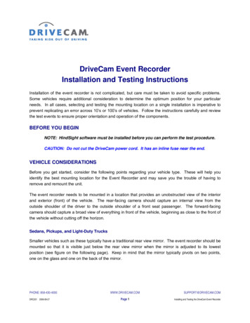
5.Mount the VER in the bracketA) Plug the HUB Interconnect Cable (14 ft.) into the VER.B) Place the VER in the bracket.C) Adjust the VER so that it hangs vertically (plumb).D) Secure the VER in the bracket using the two Torx screwsand Torx wrench (provided).Washer Placement:The large plastic washer on the left side of the bracket is designed topartially cover the cable connector so that it cannot be unplugged.The plastic washers can be easily removed from the metal bracket if youneed to switch sides after mounting.Make sure the larger of the two washers is on the left side of the bracket.6.Route the HUB Interconnect CableYou may need to remove the window and door trim to route the cable underneath. These typically snap on and offusing special clips. In vehicles with side and curtain airbags, these clips are often one-time use and may need to bereplaced after removal. Please refer to the vehicle service manual for information.WARNING: When installing the cable in a vehicle with SIDE OR CURTAIN AIRBAGS, be certain that neither the cable noryour installation activities interferes with any airbag related mechanisms or otherwise risks affecting airbag deployment.A) Starting just above the rear view mirror, route the cable under the trim or headliner across to the door pillar.B) Route the cable down the door pillar underneath the vertical door/window trim then out under the lower part ofthe dashboard to the location where the 5-Port HUB will be mounted and the electrical connections will be made.Secure the Cable:Make sure the cable is secured and cannot come loose. We recommend using cable ties every few inches along theroute to secure it in place. Keep the cable clear of any sharp edges, moving parts and cannot get pinched in the doorjam. Be very careful working around vehicle airbags.DriveCam 5-Port HUB Installation (304-C)6
7.Electrical connectionsThe black, red and brown wires are the three required connections for the VER to function. The red wire providesprimary power and must be connected to a continuous power source. The brown wire is an ignition-sense, used by theVER to activate the IR Illuminator (page 12) when the vehicle ignition is switched on. The black wire is ground.A) Find a suitable location to make electrical connections (usually under the dashboard or vehicle electrical panel).B) Connect the wiring to the vehicle as described below.C) Test the connections in steps 9 and 10 before finalizing the connections.Connecting the RED WIRE to a 12V-24V power source that is ALWAYS ONThe VER requires a power source that is not controlled by the key nor any other device or switch. This connection isusually made just after the fuse box on the battery-side of any vehicle control modules. Use a voltmeter to make surethe circuit provides continuous 12V or 24V power when the key is removed from the ignition and all lights, devices andswitches are off. Test this connection in Step 9.Current Draw:If you’re tapping into an existing vehicle wire, make sure it can handle the additional current draw ofthe VER. A wire that reads 12V on a voltmeter may not necessarily be able to supply enough currentto the existing circuit and the VER. The gauge of wire being tapped into provides a good indication. Alarger gauge wire is often the best choice, but make sure to test it with a load.Connecting the BROWN WIRE to a 12V-24V power source that is IGNITION-SWITCHEDThis connection senses when the ignition is switched on. This requires a power source that is “on” only when the key isturned all the way forward to the “on” position and when the engine is running. It’s very important that this isconnected properly. Test this connection in Step 10.Common Error: This connection is often (mistakenly) made to a modulated circuit – one that comes out of a computercontrol module running some subsystem in the vehicle – which can give false ignition on/off signals.To avoid this, make sure to connect this wire to a circuit that is on the battery side of any modules.Consult the vehicle wiring schematics or a local authorized dealership to obtain this information.If wires need to be extended, extend the ground wire first. If you must extend the red or brown wires, keep them asshort as possible. If the extended length exceeds 16 inches, place an inline fuse (1-3 Amp) between the extended wireand the power connection. You may cut the Inline Fuses (shown above) and move them to the end to the extension ifneeded. The gauge of wire used for the extension must be the same gauge as the power cable wires or larger.DriveCam 5-Port HUB Installation (304-C)7
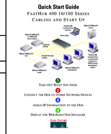
8.Connections to the 5-Port HUBThe 5-Port HUB has a silicone shell that covers the portsand cable connectors, protecting them from corrosionand damage.We recommend using the shell with all installations.We also recommend applying dielectric grease to allcable connectors before plugging them into the HUB.A) Remove the shell from the HUB. Refer to theconnection diagram on page 3 to determine whichcables plug into which ports on the HUB.B) Cut about 1/8 to 1/4 inch from the tip of the shell sleeve above the Cameraand Battery Portson the HUB.The sleeve should fit tightly around each cable to ensure maximum protection from corrosion. The smaller opening,however, may make it difficult to push the cable connectors through. The silicone sleeves will stretch, but you mayneed to apply a lubricant (such as dielectric grease) to the connectors, allowing them to slip through more easily.C) Press both sleeves down through the shell (invert them inside-out).D) Push the HUB Interconnect Cable and HUB Power Cable through the inverted sleeves until they poke through theother side. See notes below.E)Pull both sleeves back up through the shell.F)Plug the cables to the HUB.G) Proceed to the next page to test the connections.Note:If you’re planning to install the GPS Antenna (page 10) and/or Remote Trigger (page 11), you may connectthose cables into the HUB at this time as well. Repeat the steps above for the GPS and/or RT Ports on the HUB.DriveCam 5-Port HUB Installation (304-C)8
8.Test the RED WIRE connection (continuous power)Once the power and ground connections are made and the vehicle ignition is switched on, the status light to the right ofthe interior-facing lens should be lit (either a red or green light).Note: VERs are configured for hibernation mode, meaning it will automatically switch off (status lights will go dark)after the vehicle ignition has been off for a certain amount of time (15 minutes – several hours). Switch on the vehicleignition or press one of the VER buttons to “wake up” the VER from hibernation. See page 12 for more information.A) Wait about 30 seconds after connecting power (red) and ground (black).B) Turn the key to the Ignition / Switched-On position. The status light to the left of the lens will light solid green forabout 30 seconds after power is first applied and then switch OFF. The status light to the right of the lens shouldthen switch ON and stay on (see note above).Other status light behaviors that are commonly seen:Left light blinking green: Searching for a wireless signal.Right light blinking red: Data transfer in progress.Right light blinking red & green: Event recording in progress.Both lights blinking red & green: Firmware upgrade in progress.C) These behaviors may continue for several minutes. All of them indicatethat the VER is properly powered. Go to step 9.Errors: If the status lights did not light at all, check the wiring and fuses.If you see any other status light behaviors, contact DriveCam Technical Support at (866) 910-0403.9.Test the BROWN WIRE connection (ignition-switched power)Underneath the translucent cover surrounding the interior-facing lens are six small, infrared lights. These are the VER’sInfrared (IR) Illuminators, providing infrared light for recording video in low light situations. These lights can only beseen when they are lit, and they are only lit when power is being sensed through the brown wire (i.e. when the engine isrunning or when the key is turned all the way forward to the ignition ON position).A) Turn the key to the Ignition / Switched-On position.B) Look closely for the six red lights underneath the translucent cover.C) Turn the key to the OFF position. The six red lights should go out.D) If the test worked as described, the brown wire has been connected properly. Go to the next page.If the test did not work as described, try it again in a darker area or cup your hands around the cover; the lights canbe difficult to see. Next, check the wiring and fuses. It may have been connected to a modulated circuit (page 7).DriveCam 5-Port HUB Installation (304-C)9
GPS Antenna InstallationDriveCam’s GPS Antenna must be mounted in an area of the vehicle that receives good GPS satellite signal reception. Theantenna has an attached 10 foot cable that plugs into the GPS Port on the HUB (see diagram on page 3). Make sure themounting location allows for connection and easy routing of the cable.Complete steps 1 – 10 of the Basic Installation before installing the GPS Antenna.A) Select a location to mount the GPS Antenna (see mounting guidelines below).B) Route the GPS Cable to the 5-Port HUB, through the rubber shell (page 8) and then plug it into the GPS Port.C) Test the GPS Antenna to make sure it’s in a good location and receiving a GPS signal:The light on the antenna will blink (red) after it is plugged into the HUB and powered. It will blink slowly (about onesecond on and one second off) when searching for a GPS signal and then blink rapidly when a signal is found.D) Secure the antenna and cable in place. Make sure the cable is secured out of the way and will not come loose.GPS Antenna Mounting GuidelinesThe ideal mounting location allows line-of-sight reception from the GPS satellites in orbit above.GPS signals will not penetrate metals of any kind. Coated (tinted) windows may also block signals.GPS signals will penetrate glass (uncoated), plastic, Styrofoam, fiberglass, wood, carpet and upholstery.The GPS Antenna is not designed for external use – it must be mounted inside the vehicle.On the top of the dashboard: Secure the GPS Antenna flat on the dashboard with tape, Velcro, or magnet. Tuck the GPSCable into the gap between the dashboard and the windshield (wrap with tape for a snug fit if necessary) then route thecable across and under the dashboard for connection to the HUB. This location usually provides the best signal reception.Make sure the GPS Antenna is positioned under a clear section of the glass.On the front of the dashboard: Use the magnet on the back of the GPS Antenna to attach it to a flat metal surface. TheGPS Cable should be secured just below the antenna to keep it in place. Route the cable neatly under the dashboard forconnection. Velcro or tape may also be used to secure the antenna in place.Attached to the inside of a window: Use a strong adhesive tape to attach the GPS Antenna to the windshield, a side orback window, or the sunroof. The GPS Cable can be routed along the edge if the window or tucked under the trim orheadliner then under the dashboard for connection. Do not place the antenna under a dark or tinted section of the glass.Concealed under the dashboard: The GPS Antenna can be placed under any non-metal object and still receive excellentGPS signal reception. This means you can mount the antenna directly under the dashboard, on an air vent, or under aremovable plastic panel or trim piece. Make sure there are no large metal pieces between the GPS Antenna and the sky.Even small metal brackets or pipes can deteriorate the signal, depending on the size of the holes, openings, or spacingbetween the metal components. The upper portion of the dashboard is often an ideal place to conceal the antenna as itis usually composed only of plastic or foam, through which GPS signals can easily penetrate.DriveCam 5-Port HUB Installation (304-C)10
Remote Trigger InstallationDriveCam’s Remote Trigger enables drivers to trigger Remote Manual Event recordings through a conveniently mountedbutton. The button comes with a 4½ foot cable that plugs into the RT Port on the HUB (see diagram on page 3). Make surethe mounting location allows for connection and easy routing of the cable.Complete steps 1 – 10 of the Basic Installation before installing the Remote TriggerA) Select a location to mount the button.The button is designed to be mounted in a fixed panel. It should be a location where the driver will not have to reachto press the button. Nor should it be placed where the driver may accidentally press the button. The PushbuttonCollar (see below) may be fitted over the button to help prevent accidental triggers. This is optional.B) Using the proper bit size (about 1 inch), drill a hole into the panel.The button mounting hole diameter must be between 15/16 – 17/16” (24 – 27 mm) and the panel thickness between1/32 – 1/8” (1 – 3 mm), which is about the thickness of a nickel. It can be installed in a thicker panel but the buttonwill not snap into place.C) Route the Pushbutton Cable through the hole and connect the two wires to the tabs on the bottom of the button.It does not matter which tab the wires are connected.D) Route the other end of the cable to the 5-Port HUB, through the rubber shell (page 8) and then plug it into the RT Port.E) Verify correct operation by pressing and releasing the button to trigger an event recording.The right status light on the VER should begin to flash for several seconds. If not, recheck the wiring.F) Following verification, press the button firmly into the mounting hole.Note: If needed, a second Remote Trigger may be installed and plugged into the UM/RT Port on the HUB.Mounting the Pushbutton Collar (optional): Adhesive tape on the bottom of the collar holds it in place. Make sure to cleanthe mounting surface thorough
DriveCam 5-Port HUB Installation (304-C) 3 DriveCam 5-Port HUB Connection Diagram DC3 Video Event Recorder & 5-Port HUB (Basic Installation): Complete steps 1 - 10 before installing any other components. DC3 Kit: DC3 Video Event Recorder (VER), Windshield Mounting Bracket (other brackets available) & Torx Screws. 5-Port HUB Kit: 5-Port HUB Connector with Cover, HUB Interconnect Cable (14 ft .