Transcription
VM‐MQTVA/WPWhite PaperManual Quarter‐Turn Valve ActuatorsTable of ContentsIntroduction. . . . . . . . . . . . . . . . . . . . . . . . . . . . . . .Traveling Nut Actuator . . . . . . . . . . . . . . . . . . . . .Worm Gears. . . . . . . . . . . . . . . . . . . . . . . . . . . . . .Actuator Operating Characteristics. . . . . . . . . . . .Conclusion. . . . . . . . . . . . . . . . . . . . . . . . . . . . . . . .22345Val‐Matic Valve & Mfg. Corp. www.valmatic.com valves@valmatic.com PH: 630‐941‐7600Copyright 2018 Val‐Matic Valve & Mfg. Corp.
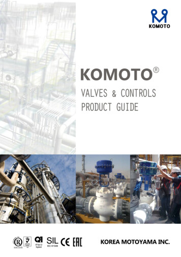
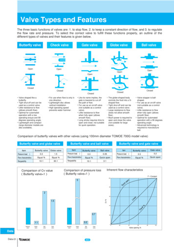
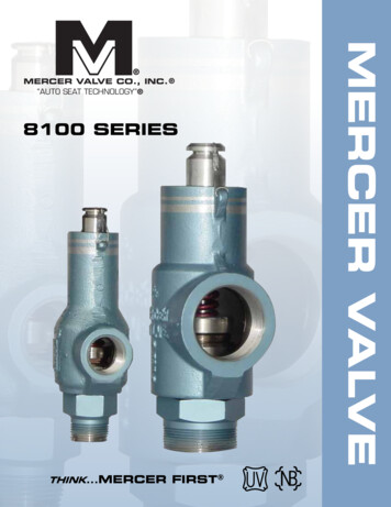
Manual Quarter-Turn Valve ActuatorsIntroductionButterfly and ball valves are typically supplied with either a traveling nut or worm gear type actuator. Bothtypes are listed in the applicable AWWA Valve Standards, C504 and C507. Each type has some importantcharacteristics that affect the performance of the valve assembly and should be understood beforeselecting the best actuator for a particular application.Traveling Nut ActuatorA common type of actuator provided with quarter‐turn valves is the traveling nut actuator. It has beenaround for over 50 years and is provided in two designs the slotted lever and the link and lever. Thetraveling nut actuator was created to match the torque characteristics of butterfly and ball valves whichhave high seating torque. Therefore, a higher mechanical advantage at the end of travel is often desirable.Threaded StemNutSealed HousingClosed StopLinkLeverValve Shaft BoreFIGURE 1. Link and Lever Traveling Nut ActuatorThe traveling nut actuator consists of a sealed housing, threaded stem, threaded nut, and either a slottedlever or a link and lever. As the threaded rod is turned with the handwheel, the nut is driven to the leftand right and supported by milled slots in the housing and cover of the actuator. (Figure 1) The nut inturn drives the lever, which in turn drives the valve shaft through 90 degrees of travel.On a link and lever traveling nut actuator, the traveling nut is connected to the lever with a link. When thenut is at the right side of the housing in the photo, the link is near vertical orientation. At this location,travel of the nut provides a small change in lever rotation. Hence, at the right end (closed position) themechanical advantage of the actuator can be twice that in the center or left position. The traveling nutactuator therefore matches the torque requirements of the valve.2
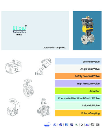
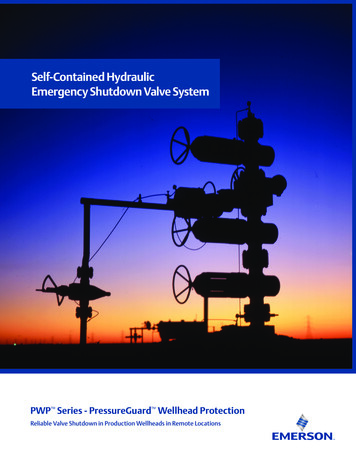
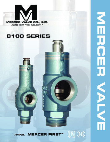
Manual Quarter-Turn Valve ActuatorsOn a slotted lever traveling nut actuator, the traveling nut acts directly on the lever. In this design, thelever as a slot in which the traveling nut slides as it moves along the threaded stem. On a standard slottedlever actuator, at either the left or right end of the stem, travel of the nut provides a small change in thelever rotation and resulting in greater mechanical advantage.Threaded StemClosed StopLeverFIGURE 2. Slotted Lever Traveling Nut ActuatorA traveling nut operation can vary from 10 to 100 turns, and for large valves (i.e. greater than 36 in.), spurgears or bevel gears are provided. The closed and open stops of these actuators are typically threadednuts that are pinned to the threaded stem for link and lever actuators. Because a high amount of torquecan be resisted between two nuts jammed together and because the stop design does not apply a load tothe housing, the stops are usually rated to 450 ft‐lbs. This high torque rating prevents many valve failuresin buried service. Val‐Matic offers a special externally adjustable closed stop where the adjustment nutextends through the housing for easy access (Figure 1). The stops of a slotted lever actuator are externalbolts with lock nuts (Figure 2).Traveling nut actuators are usually constructed of an iron housing, steel links, and a ductile iron lever andare more economical than worm gear actuators. They are more economical than worm gears because thebronze worm gear is not needed, and they provide their greatest mechanical advantage at the closedposition to match the requirements of the valve. Traveling nut actuators are the standard actuator formost AWWA butterfly and ball valve manufacturers. These actuators are designed and made by each valvemanufacturer and designed specifically for these valves.Worm Gear ActuatorsEarly butterfly and ball valves were provided with worm gear type actuators, which feature a sealed ironhousing containing a hardened steel worm that drives a large gear, sometimes called a segment or sectorgear. Adjustable bolts are provided to limit the travel of the actuator and precisely position the valve inthe open and closed positions.A basic worm gear actuator converts about 20 turns of the input shaft rotation into the 1/4 turn necessaryto operate the butterfly valve. This operation translates into a mechanical ratio of about 80:1. However,with consideration to the friction in the gear faces, the efficiency of the actuator is only about 30%resulting in a mechanical advantage of about 25:1. Hence, if it takes 500 ft‐lbs on the valve stem to operatethe valve, then the input torque needed on the actuator is only 500/25 or 20 ft‐lbs. When the input torque3
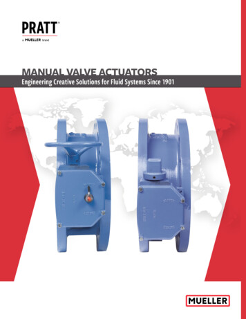
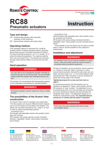
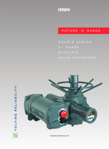
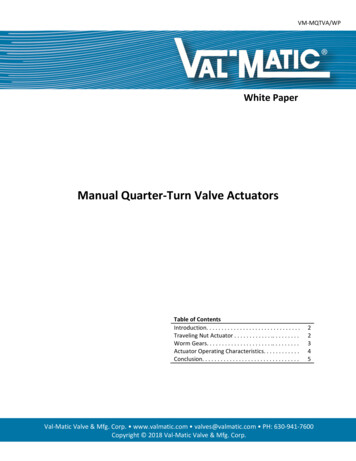
Manual Quarter-Turn Valve Actuatorsexceeds 150 ft‐lbs or 80 lbs pull on the handwheel, spur gears are provided on the input side of the housingto provide additional mechanical advantage.Worm gear actuators can be provided with handwheels for above ground service or 2” AWWA nuts forburied service. For buried service, the input shaft is made corrosion resistant stainless steel, the housingis packed with grease, and the indicator is replaced with a blind cover. One limitation of the worm gearactuator is that the closed stop design is usually limited to a torque of 300 ft‐lbs because all of the torqueis transmitted to the housing as force against the stop bolt. When a valve is buried, maintenance workerscan sometimes exceed that torque and damage the actuator.The worm gear actuator is a reliable actuator and is available from many alternate suppliers. However, itscost can be high given that its linear torque characteristic does not match the characteristic of the valve.It also provides external closed stop adjustment, which can be helpful in above ground applications.WORMSQUARE KEYSEGMENT GEARVALVE SHAFTCLOSED STOPFIGURE 3. Worm Gear ActuatorActuator Operating CharacteristicsThe last important consideration in selecting an actuator is the different operating characteristic of thetwo types. The worm gear has a linear characteristic which means that for every turn of the handwheel,the valve is rotated the same amount. Traveling nut actuators, on the other hand, exhibits “characterizedclosure.” For a link and lever actuator, characterized closure means that during the first half of closure,the valve shaft is rotated rapidly, and during the last half of travel, the valve shaft is rotated slowly towardthe closed position. For a standard slotted lever actuator, characterized closure means that during the lastportion of travel the valve is rotated slowly into the closed position. During the midstroke of travel, thevalve is rotated more rapidly. This difference in travel is a result of the geometry of the link and lever orslotted lever mechanism. The benefit of characterized closure is that the valve is closed during its lastportion of travel slowly, which can reduce pipeline surges or water hammer.4
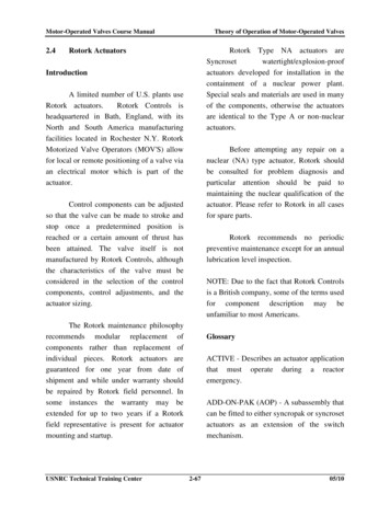
Valve Position (% Open)Manual Quarter-Turn Valve ActuatorsLINEAR CLOSURECHARACTERIZED CLOSUREActuator StrokeFIGURE 4. Actuator Operating ComparisonConclusionIn the waterworks valve industry, about 75% of the manual actuators provided today are of the travelingnut type. In the wastewater industry it is predominately plug valves with worm gear actuators. Travelingnut actuators are more economical than worm gears, withstand higher input torques, and providecharacterized closure. Given all of its advantages, the traveling nut actuator continues to be the mostpreferred actuator for butterfly and ball valves.DisclaimerVal‐Matic White Papers are written to train and assist design engineers in the understanding of valves and fluidsystems. Val‐Matic offers no warranty or representation as to design information and methodologies in thesepapers. Use of this material should be made under the direction of trained engineers exercising independentjudgement.5
actuator is that the closed stop design is usually limited to a torque of 300 ft‐lbs because all of the torque is transmitted to the housing as force against the stop bolt. When a valve is buried, maintenance workers can sometimes exceed that torque and damage the actuator.