Transcription
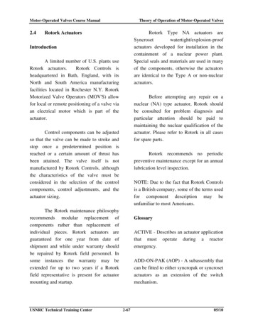
ROTORK ‘A’ RANGEDOUBLE SEALED3 - PHASEELECTRICeVO LV I N G R E L I A B I L I T YVA LV E A C T U AT O R SPublication E210E issue 4/01
2Features of the ‘A’ Range2ESTABLISHED LEADERS IN ACTUATION TECHNOLOGYReliability through double sealing3Reliability through design simplicity4Performance6‘A’ Range variations8As one of the world’s leading manufacturers of actuation productsRotork has built as enviable reputation as the supplier ofequipment which is both well-developed and durable. With overforty years of experience of long-term installations in allenvironments we have evolved a design of uncompromisingreliability. Today Rotork actuation equipment is ahead of the fieldin operating and safety applications for industry.Failsafe Systems9Specification summary10THE’A’ RANGE‘A’ Range actuators combine the qualities of a robust electricmotor and a well proven mechanical drive of the utmost simplicity.In addition, total environmental sealing and Rotork’s positiveattitude to quality, result in an actuator of the utmost reliability.ROTORK ‘A’ RANGE SYNCROSET ACTUATORS AREPARTICULARLY SUITABLE FOR: Applications where actuators with separate mounted starterswould be preferable. For example, where there are high levels ofvibration, high ambient temperatures or where accessibility to themotor operated valve is limited after installation. Installations where traditional electro-mechanical integralcontrols are preferred for the continuity of house specifications. Sites using DC or single phase power supplies. Failsafe operation by pneumatic or battery power.For most 3 phase applications the Rotork ‘IQ’ actuator providesthe best combination of economy and performance for themotorisation of valves and dampers. (See Publication E110E)
3ROTORK ‘A’ RANGE.RELIABILITY THROUGH DOUBLESEALING OF ELECTRICAL ENCLOSURESWithout double sealing, investment in modern sophisticatedcontrols can be rendered worthless, since moisture and dirtingress will cause gradual, if not immediate, electrical ormechanical failure.Rotork ‘A’ Range Actuators do not breathe. They are doublesealed, watertight and dust tight to IP68 suitable for submersion toa depth of 3 metres for 48 hours - even in their flameproof versions.ROTORK DOUBLE SEALING SOLUTIONDuring construction, cabling or commisioningDuring operationThey do not rely upon the care of the site electrician to fully sealthe cable gland in order to maintain the integrity of the internalelectrical equipment.Some of the manufacturers try to imitate the double sealing byusing enclosed limit switches. With this design approach anycontactors and travel measurement mechanisms are still at riskfrom environmental effects.Other ‘sealed’ designs
4ROTORK ‘A’ RANGER E L I A B I LT Y T H R O U G H D E S I G N S I M P L I C I T YMECHANICAL SPECIFICATION1 LOW INERTIA/HIGH TORQUE MOTORThree phase class F insulated squirrel cage motor of special hightorque low inertia design, 15 minute rated with cyclic durationfactor of 25% at 33% of actuator output rated torque giving atemperature rise not exceeding the permitted for Class Binsulation. Peak torque is rapidly produced from starting and themotor has extremely low overrun when switched off. The windingthermostat provides accurate temperature sensing independent ofambient temperature conditions to optimize the motor’s thermalcapacity2 TORQUE SPRINGSThe torque produced by the motor is sensed independently ofvoltage fluctuations. The pack of disk springs attached to the endof the motor shaft provides some mechanical resistance to thenatural tendency of the wormshaft to move laterally when underOnce the actuator stroke has been set to suit a particular valve,no resetting of the mechanism is necessary if the actuator istaken off and replaced on the same valve. Winding the valve fullyopen and shut will re-position the mechanism.In addition, two Open and two Close auxiliary switches areprovided as standard for remote indication or interlockingpurposes.A mechanical 3 position pointer and dial showing the valve to befully Open, Shut or in an Intermediate position, repeats themovement of the limit switch striker, enabling start-up personnelto check switch setting with out removing the cover. WithSyncropak, the dial is illuminated Red/White/Green for Open,Intermediate and Shut by an internal lamp. See page 10 foradditional indication features.5 THRUST BASEAll valve thrust is absorbed in the cast iron thrust base whichsupports the output shaft by means of a thrust bearing. Thereforeno thrust is taken up by the gearcase. This has the followingadvantages: Weight saving for the gearcase Even if the gearcase is damaged the valve stem remainssecured and unauthorised valve motion leading to system failureswill not occur. The gearcase can be opened for examination with the valve inservice without releasing the valve stem.load. A mechanical setting is made in the combined torque/travellimit switch mechanism (see 4) in order to switch off the motorwhen a set proportion of torque has been reached. Thrust base bearings are permanently lubricated from thegearcase oil-bath, therefore external greasing sometimesassociated with detachable designs is eliminated.3 SEPERATELY SEALED TERMINAL COMPARTMENTPermits connection using various cabling practices includingFlameproof Exd cable glands. Internal sealing of the terminalarea ensures the integrity of the electrical equipment even duringsite wiring in wet locations. In a fire, the base, thrust bearing and drive bush will retain theclosed or open valves in a secure position and will meet therequirements of API600 relating to temperature.4 LOCAL INDICATOR, TORQUE AND LIMIT SWITCHESWhen the hand/auto lever is engaged in the manual position, itdisengages the electric drive mechanism and enables directoperation of the output shaft by the handwheel.The unique combined torque and travel limit switch mechanismallows the same actuator to be specified for any type of valve, eg.either for: Travel limitation as in the case of the closed position of aparallel slide valve or Torque switch as in closing the gate of a wedge gate valve.The actuator can therefore be moved from any one valve type toanother in a plant provided the torque range is correct. Inaddition, the torque switch latch prevents the torque switchesfrom interfering with operation during unseating. The endposition limits are easily and accurately set to suit a wide rangeof valve sizes.6 MANUAL OPERATIONA geared side mounted handwheel is provided as standard onactuator sizes 70A and larger and is available as an optionalextra on sizes 14A and larger. As the hand/auto clutch is positioned on the low speed outputshaft, power operation can be transferred to manual control inorder to stop valve motion, if required. Syncroset actuators canbe stopped locally in emergencies in this way, if running underremote control. Hand operation of the valve is still possible even if the actuatorgearing has failed.
5ROTORK ‘A’ RANGE Seating and unseating is assisted with the hammerblow effectfeature so that hand operation is as quick and effective ascomparable manual valves. Motor operation is automatic and instantly restored when themotor is started. The declutch lever is padlockable in Hand toprevent motor drive, or in Auto to prevent handwheel drive. Incombination with the Syncropak selector switch locked in ‘Off’,declutch locked in Auto will prevent any form of operation for safeworking downstream of the valve.7 DRIVE BUSHINGDetachable drive bushing, machinable to suit valve stem,underhung for convenient valve adaptation (see page 7).ELECTRICAL SPECIFICATIONSYNCROSET CONTROL SYSTEMThe Rotork Syncroset actuator comprises a 3 phase motor,reduction gearbox, torque and limit switch mechanism, valveposition indicator and space heater. All integral connections arebrought out via individually number identified wires to a terminalcompartment with threaded conduit entries. Reversing contractorsmust be separately procured and installed.Syncroset actuators are particularly suitable for situations inwhich the equipment at the valve location must be minimised.Where conditions permit it is possible to supply Syncrosetactuators with integral local control push-buttons and lockableselector switch.8 GEAR CASEOil-bathed gearcase is sealed for any operating angle to providemaintenance-free reliability and to avoid ‘tunnelling’ problemsassociated with grease-filled designs.9 QUALITY CONTROL SEALShows actuator has passed full Rotork performance checks.10 STANDARD ALTERNATIVE CONDUCT ENTRIES 1 off 40mm, 2 off 32mm metric BS3643 1 off 1.5 in, 2 off 1.25in, ASA NPT 1 off PG29, 2 off PG21With Syncroset watertight actuators, 7A through 16A only the twosmaller entries of each option are supplied (3 entries areavailable to special order)SYNCROPAK CONTROL SYSTEMThe Rotork Syncropak actuator comprises everything needed tooperate a valve from a 3 phase supply: motor, reduction gearbox,limit and torque switch mechanism, space heater, reversingcontactor starter with fused control transformer, illuminated dialindicator, Open/Stop/Close push-button and padlockableLocal/Off/Remote selector switch all as a factory wired, testedand sealed package with three threaded conduit entries. Theinstallation of Syncropak actuators requires only 2 cables and 19site terminations. Responsibility for performance is undivided andis proved by testing at each stage; by the actuator manufacturer the valve maker - the installation contractor, with only 3 phasehaving to be connected.
6ROTORK ‘A’ RANGEPERFORMANCE SUMMARYPERFORMANCE DATA FOR 3 PHASE ACTUATORSActuator output speedsrpm at 50Hzrpm at 5144*172*Ft lbf192*230*Nominal 91AR95AZ30002200* Refer to Rotork if these speeds are required for direct mounted gatevalve applications† For Full motor data, refer to publication E230E13.017.44.86.515.621.05.87.8** Torque rating is maximum torque setting in both directions. Stall torquewill be 1.4 to 2.0 times this value depending on speed and voltage.If maximum torque is required for more than 20% of valve travel refer toRotork.
7ROTORK ‘A’ RANGEMECHANICAL DATAActuator N/A73ins1-11/2221/427/827/8N/A27/8Group ‘A’ couplings (thrust)†Thrust ratingStem acceptance diameterType ‘A1’ (maximum)RisingNon-risingType ‘AZ’ (maximum)RisingNon-risingGroup ‘B’ couplings (non-thrust)†Stem acceptance diameterType ‘B1’ (fixed)mm42-6080100100120N/AN/AType ‘B3’ (fixed bore)mm20-304050505050N/AType ‘B4’ heel ratioOptionalFlange sizeISO 5210F10F10F14F16F25F25F30*F25F30MSS SP-102FA10**FA14FA16FA25FA25FA30*FA25FA30* 90A with Group B3 and B4 couplings have flange size F25.** 13AL has FA10 base dimensions except that spigot diameter is 2.76”.† Valve stems or shafting should be adequately supported to prevent radial loads being imposed on the actuator drive bushings.
8ROTORK ‘A’ RANGE‘ A ’ R A N G E VA R I AT I O N SSIDE MOUNTINGFIREPROOFINGLarge or slow speed valves can be motorized through thrusttaking bevel or spur gear operators on which the electric actuatoris mounted. Because of their inherent high efficiency, such gearsprovide for satisfactory handwheel operation. The gearboxes arenormally provided by the valvemaker, but can be supplied byRotork in combination with actuators.Standard ‘A’ range Syncropak and Syncroset actuators areavailable complete with fireproofing system which will guaranteemotorised valve operation for up to 30 minutes after thecommencement of an oil fire at the MOV installation. Satisfactorytests have been conducted where operating MOV’s weresubjected to temperatures of 1065 C (1942 F) for upto 30minutes.HIGH SPEED ACTUATORSWhere unusually are high speeds are required Rotork torquelimiting brake can be supplied to prevent excessive valve seatloading.PLUGS AND SOCKETSFor applications where quick and simple method of disconnectingand reconnecting the power supply and control cables to anactuator is required, Rotork Syncropak and Syncroset actuatorsup to size 90A can be fitted with plug and socket connectors asan alternative to conventional hard wiring. The unique Rotorkdoubling sealing feature is maintained even with the plugsdisconnected, giving protection to IP68. See publication AE4/0.2NUCLEAR ACTUATORS TYPE NAType NA Syncroset actuators have been specially developed,qualified and supplied for safety related duty in nuclearpowerlpants, particularly those involving light water reactors. Theparamount importance of proper and auditable qualificationhaving been recognised and documented primarily in the USA, thebasis of qualification are the US standards IEEE 282, IEEE 323,IEEE 344 and IEEE 382, Rotork being a participant member of thecommittee responsible for their drafting. See publication AE 1/4QUARTER TURN VALVESProprietary gearboxes can be offered in combination with ‘A’Range actuators to provide increased torque at reduced speedsfor the operation of ball, butterfly and plug valves.FLOOR MOUNTINGFloorstands with upward and downward stub shafts are availablefor coupling via customer’s shaft and universal joints to remotevalves.DAMPER ACTUATIONSingle blade and multi-vane dampers can be motorized either bydirect connection to the spindle or by lever-arm. Apply to Rotorkfor details.ACTUATOR FOR LOW TEMPERATURESStandard actuators are designed to operate at temperaturesdown to -30 C, -22 F. Special provision is made at extra cost fortemperatures of -40 C, -40 F or -60 C, -76 F.
9ROTORK ‘A’ RANGE‘ A ’ R A N G E VA R I AT I O N SThe combination of two wire cabling and elimination of controlinterface greatly diminish the design engineering required as wellas reducing commissioning time (less possibility of error) therebyachieving even greater savings.The Rotork two wire control system can easily be fitted orretrofitted to the ‘IQ’ Range, 1400, 1600 Series ‘A’ Range or ‘AQ’Range or ‘Q’ Range actuators. It can also be used with otherdevices such as pumps, level gauges, sensors etc. Seepublication S000E.FAILSAFE SYSTEMSSINGLE PHASE ‘A’ RANGESyncropak and Syncroset actuators up to size 30A are availablefor use with single phase power supplies of 110, 220 and 240Volts 50Hz and 120V, 60Hz.DC ‘A’ RANGEDC powered Syncroset and Syncropak actuators are available forapplications where valve operations must be maintained even inthe event of single or 3 phase power failure. The DC version ofthe ‘A’ Range actuator has been developed from the standardSyncroset and Syncropak watertight and Factory Mutual certifieddesigns, using a flange mounted permanent magnet DC motor.The range of supply voltages catered for as standard is 48V and110V DC. For further information see publication E221E.FOLOMATIC CONTROLThis electronic package enables a Syncropak actuator to positiona valve in proportion to analogue current or voltage signal. It issuited to systems with relatively slow rates of change, eg. levelcontrols in water and sewage systems. See publication AE4/0.1.Not available with size 13 actuators.PAKSCAN TWO WIRE CONTROLThe Rotork two-wire control system for valve actuators offersconsiderable cost savings on cabling and control interface as wellas design engineering.The system consists of a master station which controls andmonitors up to 240 actuators via field units mounted in theactuators and connected by a two wire loop.The total installed cost of the conventional multicore cabling canbe as much as twice the cost of the valve actuators. With atypical installation, such as an oil tank farm, savings of up to 75%can be made by the use of the two wire system, though savingswill vary, depending on complexity and control distance.Further considerable savings can also be achieved if theactuators are controlled by computer, since the master stationequipped with RS232C port can be connected without the needfor further interface.A standard Rotork electric motor actuator provides a simpleeconomic and reliable means of operating valves under all normalconditions except during electrical supply failure when the valvestays put. If the system is such that the valve must be operatedduring power failure, some form of stored energy is essential.Rotork are able to offer two such stored energy systems.DC Actuator Emergency Shutdown SystemThis system is based on the use of Rotork DC powered ‘A’ RangeSyncropak actuator in conjunction with an AC fed DC batteryconsole. The system is designed to allow actuators to bepowered from the DC battery source under both normal operatingconditions and emergency shutdown conditions. Thiscontinuously confirms the availability of the DC power system. Inaddition a relay fitted inside the Rotork DC Syncopak actuatormonitors availability of the DC battery supply and the actuatorcontrol circuit together with a battery status indication relay in thebattery console. Each battery cubicle is designed to carry a singlephase battery charger together with batteries for powering oneDC Syncropak actuator. The battery cubicle also includes a relayfor monitoring the single phase input power supply to the batterycharger. Contacts of this relay are used to indicate AC powersupply failure, initiate ESD operations of the actuator and todisconnect any existing control signal. While the actuator maybesupplied as watertight only or watertight and flameproof, FactoryMutual Certified, the battery cabinet is only available as watertightIP66. See publication E221E.Electro-Pneumatic Valve Actuator Emergency ShutdownSystemsThis uses the Rotork Type PA failsafe electro-pneumatic actuator.PA actuators are Rotork ‘A’ Range Type 11A, 16A, 30A, 40A, 70Aor 90A actuators to the Syncroset or Syncropak Specificationhaving a pneumatic air motor flange mounted onto the electricmotor. Since the pneumatic motor maybe powered by stored orline gas at 5-7 bars (80 to 100psi). The pneumatic operation ofthe PA actuator requires the installation of suitable pneumaticcontrols. Rotork is able to supply lockable and weatherproof, IP55cabinets containing these controls and suitable for either wall orstand mounting.
10ROTORK ‘A’ RANGE4/1Publication number for moredetailed informationBasic specificationStandard ‘adder’ optionsS P E C I F I C AT I O NE210E210E210E210Illumination of local indicator ntegral reversing contactor starter mechanicallyand electrically interlocked.E210E210NASycroset2200 SeriesE210Syncropak1400 SeriesE210Syncropak1600 SeriesThree phase electric actuator with double sealedwatertight enclosure IEC IP68 (submersion inwater to a depth of 3m for 48hrs. Other nationalenclosure standards also complied with, ie. CSA,NEMA, BS5410 specifications) complete withsegregated terminal area to IEC. Declutchablelockable emergency handwheel. Class F insulated15 min. rated, low/high torque motor withthermostat protection. Combined torque/limitswitches for open and closed position and 2 eachauxiliary limit switches for remote lamp indicationor interlocks. 3 position local indicator.Sycroset2200 SeriesMAIN DRIVE UNITSyncropak1400 SeriesSUMMARYSyncropak1600 SeriesSpecial optionsBlinker switch for valve motion indicator.4/24/24/2Current Position Transmitter (CPT) for any rangebetween 0 and 50mA,4/24/24/2Integral smooth DC power supply for CPTtransmitter for external lamp indication.4/24/2NA110 to 120 Volts AC supply for external driving ofvolt meter or lamps - 20VA4/24/2NA‘Valve running’ indication (motor energised).4/24/2NA‘Valve available’ indication.4/24/2NA(A) Open/Stop/Close or Open/Close with midtravel reversal. Control maintained or ‘push to run’4/24/2(A) From volt free push-buttons up to 600 metersaway from actuator.4/24/2NANot integrally suppliedREMOTE CONTROL OPTIONSLocal Open/Close/Stop push-buttons withlockable local Open/Close/Off selector switch.E210Additional time based motor protection system.4/2NANAAutomatic phase rotation correction with singlephasing motor protection.NANANA(A) From volt free push-buttons- but from longerdistances.4/24/2Phase rotatation discriminator with singlephasing motor protection.4/24/2NA(A) From Panel-fed remote controls with specifiedcontrol supply.4/2NAInstantaneous reversal protection.4/2NANA4/2NA(B) From proportional Controller giving signals of0-50mA Volts or 0hms with any zero offset.4/0.14/0.1(C) 2 wire open/close from make/break switch.4/2(D) Emergency shutdown circuit4/2Single phase power supplies.E210E210E210E2104/2E230DC power supplies.E221Flameproof enclosures ie CENELEC,factory Manual.Pneumatic failsafe ‘PA’ system fitted to 3 phaseactuators only.1/3Two speed or low speed operation4/21/31/3INTERLOCK AND MONITORING FACILITIESNATime rating greater than 15 minutes and/orhigher motor insulation.ADDITIONAL VALVE STATUS INDICATION FACILITIESPotentiometer for remote continuous indicationAdd-on-Pak 1 unit comprising potentiometer forcontinuous remote indication and 6 additional limitswitches adjustable in banks of 3 to any valveposition. Continuous local indicator.(A) From Panel-fed remote controls withunspecified control supply 12 Volts to 120 VoltsAC or DC.4/24/24/2Interlock circuits to prevent/permit either or bothclosing and opening movements.4/24/2Alarm or incomplete travel, sequence failure orunauthorised hand operation4/24/24/24/2Alarm of local control switch set to ‘stop’, ‘off’ or‘local control’. Alarm of fuse blown, motoroverhead, power supply disconnected, incompleteor incorrectly wired, integral monitor relay.Alarm of above individually supplied.4/24/24/2
11STANDARD FINISHLIFE TESTSIron castings are fettled to present a smooth surface after whichthe are dipped, before machining, in a synthetic red oxide primerto seal all surfaces.These are based on 10,000 valve operating cycles at average of1/3 seating torque. the actuator is also stalled against solidobstruction 50 times to prove durability.Aluminium actuators are then suitably masked and passed on aconveyor through a aqueous degreasing plant operating at 70ºCto the spraying stage.FREQUENCY OF OPERATIONTHE SPRAYING STAGEVIBRATIONPreheated paint is applied as follows;Standard ‘A’ Range actuators should not be used on applicationswhere they are likely to be subjected to levels of vibrationexceeding the following:UndercoatMake:Type:CrodaMultipurpose zinc phosphateanti-corrosion primerRef no:TDS: 4112 (AC94)Min dry filmthickness:2.00 mils (50.8 microns)Application:Top CoatMake:Spray with electrostatic orpneumatic depositionStandard ‘A’ Range actuators are suitable for up to a maximum of60 starts per hour.Plant induced vibration- 0.5g over frequency range of 10-200Hz.Seismic- in frequency range of 0.2-33Hz, 1.0g if it is to operateduring and after the event, or 5.0g if it is only required to maintainstructural integrity.Where excessive plant induced vibration is anticipated, mountingthe actuator remote from the valve and driving through extensionshafting incorporating vibration absorbing couplings, may providea satisfactory solution.CrodaType:Air dried urethane reinforcedsynthetic alkyd resinMAIN ALTERNATIVE ENCLOSURESRef no:XY01464Colour:Charcoal grey BS4800-00A13Canadian Standards Association approved wiring andcomponents complying with CSA 4.Min filmthickness:1.00 (25.4 microns)Application:‘CSA WT’‘CSA EP’Spray with electrostatic or pneumaticdeposition. Wet on dry.Drying time:12 hours to hard dryFilm thickness:3 mils (76.2 microns)Actuators finished with our standard preparations developed forexposed locations involving salt spray, high humidity and a wideband of ambient temperatures -40 C 70 C. The finish hassuccessfully withstood a 672 hour Salt Mist Environmental Testbased on BS2011 Part 21 Ka.Canadian Standards Association approved for Class 1 Groups B,C and D, Division 1 hazardous areas. Ambient temperature -30 Cto 40 C (-22 F to 104 F)‘FM’Explosionproof Factory Mutual approved for Class 1 Groups B, Cand D, Division 1. Hazardous areas to NEC Article 500.‘CENELEC EXd’UK BASEEFA certified for EExdIIBT4 CENELEC NormEN 50018, BS5501TEMPERATURE‘CENELEC EXd HYDROGEN’Standard for ambients of -30 C to 70 C (-22 F to 158 F). For‘CSA EP’ enclosures see below. For lower or higher ambienttemperatures please apply.UK BASEEFA certified for EExdIIB H2 T4 CENELEC NormEN50018, BS5501‘CENELEC EXe’DESIGN LIFEFor isolating duty torque ratings of actuators are based on aminimum maintenance free life of 10,000 valve operations orOpen/ Close cycles assuming rated seating torque at stroke and1/3 rated torque during operation. For modulating duty ratingsplease apply.UK BASEEFA certified for EExdIIBT4 CENELEC NormEN 50019, BS5501‘CENELEC EXe HYDROGEN’UK BASEEFA certified for EExdIIB H2 T4 CENELEC NormEN50019, BS5501
UK head officeRotork Controls Limitedtelephone Bath 01225 733200telefax 01225 333467email mail@rotork.co.ukA full listing of our worldwidesales and service networkis available on our website atwww.rotork.comUSA head officeRotork Controls Inctelephone Rochester (716) 328 1550telefax (716) 328 5848email info@rotork.comAs part of a process of on-going productdevelopment, Rotork reserves the rightto amend and change specificationswithout prior notice.Published data may be subject to change.For the very latest version release, visitour website at www.rotork.comRotork Controls Inc, Rochester, USARotork Controls Ltd, Bath, UKThe name Rotork is a registered trademark.Rotork recognizes all registered trademarks.Published and produced in the UK byRotork Controls Limited.
The unique combined torque and travel limit switch mechanism allows the same actuator to be specified for any type of valve, eg. either for: Travel limitation as in the case of the closed position of a parallel slide valve or Torque switch as in closing the gate of a wedge gate valve. The actuator can therefore be moved from any one valve type to