Transcription
Example SystemsPipeFlow is a trading name of Daxesoft om
2Pipe Flow Expert Example SystemsCopyright Notice 2012 All Rights ReservedDaxesoft Ltd.Distribution Limited to Authorized Persons Only.Trade Secret NoticeThe PipeFlow.com, PipeFlow.co.uk and Daxesoft Ltd. name and logo and all related product and service names, design marks,logos, and slogans are either trademarks or registered trademarks of Daxesoft Ltd. All other product names and trademarkscontained herein are the trademarks of their respective owners.Printed in the United Kingdom - November 2012Information in this document is subject to change without notice. The software described in this document is furnished under alicense agreement. The software may be used only in accordance with the terms of the license agreement. It is against the law tocopy the software on any medium except as specifically allowed in the license agreement. No part of this document may bereproduced or transmitted in any form or by any means electronic or mechanical, including photocopying, recording, or informationrecording and retrieval systems, for any purpose without the express written permission of Daxesoft Ltd.
Pipe Flow Expert Example Systems 3Table of ContentsTable of Contents . 3Table of Figures . 4Pipe Flow Expert Software . 6Trial Mode Operation . 6Example Systems . 6Common 01 - Tanks . 7Common 02 - Flow Demands . 8Common 03 - Pipe Fittings & Valves . 9Common 04 - Tee Fittings . 10Common 05 - Enlargements & Contractions . 11Common 06 - Pump Types . 12Common 07 - Cv or Kv Control Valve Coefficients . 13Common 08 - Heat Exchangers, Cooling Coils, Chillers, Fan Coils . 14Common 09 - Sprinklers / Spray Nozzles . 15Common 10 - Flow Control Valves (FCVs). 16Common 11 - Pressure Reducing Valves (PRVs) . 17Common 12 - Back Pressure Valves (BPVs) . 18Common 13 - Closed Loop Systems . 19Common 14 - Fluid Zones . 20Common 15 - Gases . 21General 01 - Three Reservoirs . 22General 02 - Tank to Joint Outflow . 23General 03 - Gravity Flow to 3 Outlet Points . 24General 04 - Fixed Flow Pumping to 3 Tanks . 25General 05 - Fixed Head Pumping to 3 Tanks . 26General 06 - Fixed Speed Pump with Performance Curve . 27General 07 - Pressurised Pumping Stations. 28General 08 - Reverse Pipe . 29General 09 - Energy Recovery with Turbine. 30General 10 - Top Up Tanks - Closed Loop Pressurized Recirculation System . 31General 11 - Replacement Pipe Size . 32General 12 - Step By Step (User Created Example) . 33General 13 - Pressure Reducing Valves . 39General 14 - Back Pressure Valves . 40General 15 - Fire Hydrant Supply . 41Isometric 01 - Chilled Water Cooling . 42Isometric 02 - Chilled Water Campus Cooling . 43
4Pipe Flow Expert Example SystemsIsometric 03 - HVAC 3 Pumps . 44Isometric 04 - AHUs Single Pump . 45Isometric 05 - Water Distribution System . 46Isometric 06 - Water Circulation System . 47Isometric 07 - Fire Protection Sprinklers . 48Isometric 08 - Fire Protection Water Mist . 49Gases 01 - Compressed Air Distribution . 50Gases 02 - Compressed Air Zoned . 51Gases 03 - Methane Pipeline . 52Table of FiguresFigure 1 Common 01 - Tanks . 7Figure 2 Common 02 - Flow Demands . 8Figure 3 Common 03 - Pipe Fittings & Valves . 9Figure 4 Common 04 - Tee Fittings . 10Figure 5 Common 05 - Enlargements & Contractions . 11Figure 6 Common 06 - Pump Types . 12Figure 7 Common 07 - Cv or Kv Control Valve Coefficients . 13Figure 8 Common 08 - Heat Exchangers, Cooling Coils, Chillers, Fan Coils . 14Figure 9 Common 09 - Sprinklers / Spray Nozzles . 15Figure 10 Common 10 - Flow Control Valves . 16Figure 11 Common 11 - Pressure Reducing Valves . 17Figure 12 Common 12 - Back Pressure Valves . 18Figure 13 Common 13 - Closed Loop systems. 19Figure 14 Common 14 - Fluid Zones . 20Figure 15 Common 15 - Gases . 21Figure 16 General 01 - Three Reservoirs . 22Figure 17 General 02 - Tank to Joint Outflow . 23Figure 18 General 03 - Gravity Flow to 3 Outlet Points . 24Figure 19 General 04 - Fixed Flow Pumping to 3 Tanks . 25Figure 20 General 05 - Fixed Head Pumping to 3 Tanks . 26Figure 21 General 06 - Fixed Speed Pump with Performance Curve . 27Figure 22 General 07 - Pressurised Pumping Stations . 28Figure 23 General 08 - Reverse Pipe . 29Figure 24 General 09 - Energy Recovery with Turbine . 30Figure 25 General 10 - Top Up Tanks - Close Loop Pressurized System . 31Figure 26 General 11 - Replacement Pipe Size . 32
Pipe Flow Expert Example Systems 5Figure 27 General 12 - Step By Step . 33Figure 28 General 13 - Pressure Reducing Valves . 39Figure 29 General 14 - Back Pressure Valves. 40Figure 30 General 15 - Fire Hydrant Supply . 41Figure 31 Isometric 01 - Chilled Water Cooling . 42Figure 32 Isometric 02 - Chilled Water Campus Cooling . 43Figure 33 Isometric 03 - HVAC 3 Pumps . 44Figure 34 Isometric 04 - AHUs Single Pump . 45Figure 35 Isometric 05 - Water Distribution System . 46Figure 36 Isometric 06 - Water Circulation System . 47Figure 37 Isometric 07 - Fire Protection Sprinklers. 48Figure 38 Isometric 08 - Fire Protection Water Mist . 49Figure 39 Gases 01 - Compressed Air Distribution . 50Figure 40 Gases 02 - Compressed Air Zoned . 51Figure 41 Gases 03 - Methane Pipeline . 52
6Pipe Flow Expert Example SystemsPipe Flow Expert SoftwareThe Pipe Flow Expert software has been designed to help today’s engineers analyze and solve a widerange of problems where the flow and pressure losses throughout a pipe network must be determined.Trial Mode OperationYou do not need a license code to run the trial version of the Pipe Flow Expert software. When theLicense Screen is shown, the software may be run by clicking the 'Run Free Trial' button.The software is initially supplied in trial mode and this allows users to draw their own ‘small’ systems andgives access to the Example Systems, where the user can view the pipe model and ‘solve’ the system tosee the calculated results.The trial mode is intended to give users a means of assessing if the software is suitable for theirapplication. Certain features of the software are fixed for the trial version. The trial mode operation is notintended to give full access to the software.In trial mode, Pipe Flow Expert allows the user to:a. Load Example Systems – no changes to the model are permitted.Solve Example Systems to find the balanced steady state solution.View Calculated Results on the drawing, in spreadsheet format, and in PDF reports.b. Draw New Systems up to a maximum of 5 pipes – fluid is always set to water.Solve the System.View Calculated Results - in trial mode, systems cannot be saved.Example SystemsThe example systems supplied with Pipe Flow Expert may be loaded and solved using a trial installationof the software.The example systems are divided into four categories:a.b.c.d.Common Systems – Modelling Specific Items: Pipes, Fittings, Components, Valves and Pumps.General Systems – Gravity Flow, Pumped Flow (3 pump types), Energy Recovery.Isometric Systems – Chilled Water Cooling, Water Distribution Network, Fire Protection.Gas Systems – Zoned Compressed Air Distribution, Methane Pipeline Isothermal Flow.The examples range from simple systems with only a few pipes to more complex applications whichcontain over a hundred pipes. We suggest that each example system is opened and solved in turn, sothat you become familiar with the features and modeling capabilities of the Pipe Flow Expert software.
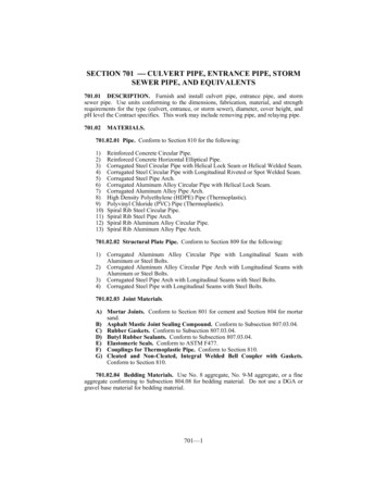
Pipe Flow Expert Example Systems 7Common 01 - TanksFigure 1 Common 01 - TanksA tank is normally used as a starting point in a system to define the source of the fluid.The liquid level in the tank, the fluid surface pressure and the elevation of the outlet point from thetank all contribute to give the potential energy of the fluid, which can provide some motive force tocreate flow.Where the fluid is open to atmosphere the fluid surface pressure should be set 0.000 psig.For a pressurized container the fluid surface pressure would be set to the pressure in the container.A suitable icon can be chosen to represent a pressurized container. The icon selected is for visualpurposes only. The choice of icon does not have any effect on the calculations.The dimensions of a tank do not need to be specified. It is assumed that the tanks are of infinite size,therefore the flow rate entering and the flow rate leaving a tank do not have to be the same.
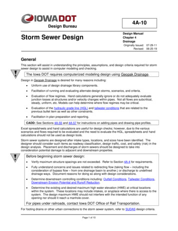
8Pipe Flow Expert Example SystemsCommon 02 - Flow DemandsFigure 2 Common 02 - Flow DemandsA flow demand specifies a flow leaving or entering a system from an external source.External out-flow leaving the system can be specified at a node.External in-flow entering the system can be specified at a nodeThe example shows four models that demonstrate the use of flow demands.a.b.c.d.Flow from source tank to a node with a specified out-flow demand.Flow from a node (with an in-flow demand) to a receiving tank.Flow between tanks with a specified out-flow demand (take off flow) at an intermediate node.A model with in-flow and the out-flow demands at the same node.Note:In the last model the flow demands have been set to the same value, which means the in-flow andthe out-flow demands are redundant.Demand flows do not set the overall flow rate at a node.Demand flows set an external flow rate either entering or leaving the node point.In this model the in-flow demand and out-flow demand cancel each other out.
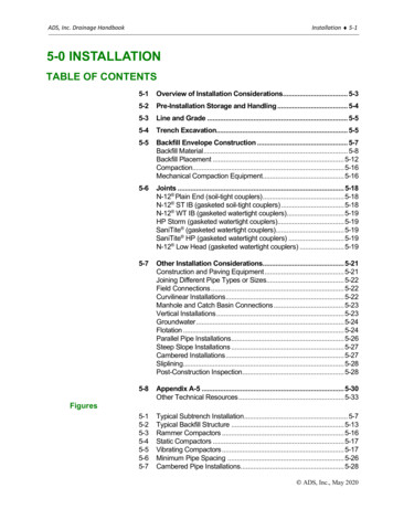
Pipe Flow Expert Example Systems 9Common 03 - Pipe Fittings & ValvesFigure 3 Common 03 - Pipe Fittings & ValvesPressure loss through Fittings, Valves and Pipe Entrances and Exits are modelled by associatingthese items with the appropriate pipe.In these examples a pipe entry K factor flow coefficient (0.78) has been added to model theprojecting pipe entrance from the left hand tank and a pipe exit K factor flow coefficient (1.00) hasbeen added to model the open pipe exit.Four standard bends and an Angled Globe Valve have also been associated with the pipes.A small bend symbol appears on the pipe to show that fittings have been included.A small valve symbol appears on the pipe to show that valves have been included.The top example shows a pipe modelled as six separate sections. Each pipe section has a fitting orvalve or entrance loss or exit loss associated with the individual section as appropriate.A pipe with a constant diameter (which may consist of many short lengths - horizontal, risers,droppers, slopes etc) and fitting/valves may be modeled as one pipe in a Pipe Flow Expertschematic as shown in the bottom model.In the bottom model the start elevation, end elevation and the overall the pipe length have been setto create an equivalent system to the one in the top model. A pipe entrance (from tank), 4 x standardbends, an angled globe valve and a open pipe exit have been associated with the single pipe.When the system has been solved it can be seen that the flow rate in both models is the same.
10Pipe Flow Expert Example SystemsCommon 04 - Tee FittingsFigure 4 Common 04 - Tee FittingsTee fittings are a special case where the flow rate through the tee will be different for each flow path,therefore two fittings should be used.One fitting is added on each flow path to model the pressure loss for the tee. The correct flow ratesalong the various paths will then be applied to the appropriate 'Through Tee' or 'Branch Tee' fittingcoefficients when calculating the fitting pressure losses.Pipe entrance fittings have been purposely omitted for clarity.There are four different situations where a Tee fitting may occur in a system, which are modelled asfollows:Case A: Diverting Tee (one branch line)'Through Tee' fitting added to the main pipe leaving the tee.'Branch Tee' fitting added to branch line pipe leaving the tee.Case B: Converging Tee (two branch lines)'Branch Tee' fitting added to a pipe entering the tee.'Branch Tee' fitting added to a pipe entering the tee.Case C: Diverting Tee (two branch lines)'Branch Tee' fitting added to a pipe leaving the tee.'Branch Tee' fitting added to a pipe leaving the tee.Case D: Converging Tee (one branch line)'Through Tee' fitting added to the main pipe entering the tee.'Branch Tee' fitting added to the branch line entering the teeUN-EQUAL PIPE SIZES:Where the pipes sizes that connect to the tee are not equal, the fitting sizes used should match tothe nominal pipe sizes.
Pipe Flow Expert Example Systems 11Common 05 - Enlargements & ContractionsFigure 5 Common 05 - Enlargements & ContractionsWhen two pipes of different diameters are joined there will be some pressure loss across thejunction, due to the change in fluid velocity.The Pipe Flow Expert database includes K factor calculators for:a.b.c.d.Sudden enlargements, where a smaller pipe feeds into a larger pipe.Sudden contractions, where a larger pipe feeds into a smaller pipe.Gradual enlargements, where a smaller pipe expands gradually to the larger pipe size.Gradual contractions, where a larger pipe contracts gradually to the smaller pipe size.The contraction/enlargement fitting 'K' factor calculation is based on the internal diameters of thepipes to be connected and requires the resulting 'K' factor to be used with the fluid velocity in theENTERING pipe.Examples are shown for:a.b.c.d.Sudden Enlargement (fitting on smaller pipe).Sudden Contraction (fitting on larger pipe).Gradual Enlargement (fitting on smaller pipe).Gradual Contraction (fitting on larger pipe).The Pipe Flow Expert fittings database also includes calculators for Rounded Pipe Entrances (fromtanks) and Long Pipe Bends.Note: In this example, pipe entrance fittings have been purposely omitted to allow focus on themodelling of contraction and expansion fittings.
12Pipe Flow Expert Example SystemsCommon 06 - Pump TypesFigure 6 Common 06 - Pump TypesA pump is added to a model by adding the pump to a pipe.Pipe Flow Expert allows three types of pump modelling:1. Flow versus Head curve (Centrifugal pump):The system will be solved with a flow rate and pump head which lies on the performance curve.The duty point for the steady state balanced solution will be plotted on the performance curve.A system curve which runs through the duty point can be shown. In the example shown, thedifference in fluid surface level is 13 ft (static head of 15ft - 2ft), so the starting point for thesystem curve has been set to 13 ft.2. Fixed Flow Rate (Piston or Peristaltic pump):The system will be solved for the set flow rate. The pump head required to generate the flow willbe calculated.Note: A fixed flow rate pump can be a useful option to find an initial pump head for a system. Theflow rate & pump head required can then be used to select a centrifugal pump with a suitableperformance curve from a specific pump manufacturer.3. Fixed Head Pump (or Compressor):The system will be solved with the head provided by the pump. The flow rate will be calculatedand reported.Note: This can be a useful option to see how a change in pump head affects flow rates at variouspoints in the system.
Pipe Flow Expert Example Systems 13Common 07 - Cv or Kv Control Valve CoefficientsFigure 7 Common 07 - Cv or Kv Control Valve CoefficientsThere are many different types of components and control valves on the market. Each will havedifferent flow / pressure loss characteristics.Control valve manufacturers usually publish a Cv flow coefficient or a Kv flow coefficient that definesthe flow / pressure loss characteristics of the valve.Cv or Kv flow coefficients are sometimes used to specify the flow versus pressure dropcharacteristics of a partially closed balancing valve.A Cv flow coefficient specifies the volume of water in US gpm at 60 F (15.55 C) that will flow throughthe valve with a 1.0 psi pressure drop across the valve.A Kv flow coefficient specifies the volume of water in m³/hour at 20 C (68 F) that will flow throughthe valve with a 1.0 bar pressure drop across the valve.The control valve in this example has a Cv flow coefficient of 139. This would give a pressure drop of1.0 psi for a flow rate of 139 US gpm of water. A flow rate of 200 US gpm will result in an increasedpressure drop of: (200/139) x (200/139) 2.07 psi (approximately 4.79 ft head of water).A control valve which has a Kv flow coefficient of 100 would give a pressure drop of 1.0 bar for a flowrate of 100 m³/hr of water. A flow rate of 200 m³/hr will result in an increased pressure drop of:(200/100) x (200/100) 4.00 bar (approximately 40.789 m head of water).In Pipe Flow Expert, add a Component object to a pipe to model a control valve with a Cv or Kv flowcoefficient.
14Pipe Flow Expert Example SystemsCommon 08 - Heat Exchangers, Cooling Coils,Chillers, Fan CoilsFigure 8 Common 08 - Heat Exchangers, Cooling Coils, Chillers, Fan CoilsMany systems include items such as heat exchangers, boilers, fan coils, cooling coils, filters, chillersand spray nozzles etc.Each of these items will have a pressure loss characteristic associated with various flow ratesthrough the item.The Component object allows any item where the flow versus pressure loss characteristic is known,to be modelled as part of the system.Add a Component to a pipe and enter values for flow rate versus pressure loss in the data table todefine the performance characteristic of the Component.Note: The Component object can also be used to specify a Fixed Pressure Drop within a system.In the example several Components have been used to model the flow rate versus pressure losscharacteristics of a boiler and two heat exchangers.The Component symbol can be changed to represent a Valve, Heat Exchanger, Cooling Coil,Heating Coil, Fan Coil, Nozzle, Radiator, Filter and more.The chosen symbol does not affect the pressure loss calculations.
Pipe Flow Expert Example Systems 15Common 09 - Sprinklers / Spray NozzlesFigure 9 Common 09 - Sprinklers / Spray NozzlesMany systems include points where flow will discharge to atmosphere.Fire Protection Systems, Crop Irrigation Systems, Golf Course Watering Systems and IndustrialWashing/Painting Plants are all examples of pipe networks where spay nozzles may be used.When a spray nozzle is included in the design it is necessary to use the flow versus pressure losscharacteristics of the nozzle to establish the flow leaving the system due the pressure differentialacross the nozzle.A combination of a Component and an End Pressure node may be used to model the performanceof a spray nozzle.The flow rate versus pressure loss values associated with the sprinkler should be entered in theComponent's data table.The End Pressure node is set to 0.000 psig, if the spray discharges to atmosphere.If the discharge entered a pressurized tank then the End Pressure node would be set to the tankpressure.
16Pipe Flow Expert Example SystemsCommon 10 - Flow Control Valves (FCVs)Figure 10 Common 10 - Flow Control ValvesMany systems need to be 'balanced' to obtain a particular flow rate, either at some outlet point oraround some loop within the system.It is often necessary to introduce some additional pressure loss to control the flow rate.Add a Flow Control Valve (FCV) to a pipe to set a specified flow rate and the pressure loss requiredacross the valve in the solution of the final system will be calculated.NOTE: A FCV cannot add pressure to generate the specified flow rate.The system pressures must already be capable of generating a flow rate which exceeds the FCV'sspecified flow. When a FCV setting exceeds the maximum natural flow rate that is possible then anerror is reported.HINT: A system model which includes a 'Fixed Head' pump & FCVs can be used to establish theminimum pump head required. Subtract the minimum pressure loss across the FCVs from the 'FixedHead' added by the pump to obtain the minimum pump head required.
Pipe Flow Expert Example Systems 17Common 11 - Pressure Reducing Valves (PRVs)Figure 11 Common 11 - Pressure Reducing ValvesPressure Reducing Valves are used to limit the pressure in the lower parts of a system.The pressure at the outlet points of this system would be high, about 70 psig at node N3, and 92 psigat node N5, if the pressure reducing valves were not included.To reduce pressure at the lower elevations, PRV's have been included at the end of pipes P1 & P3.PRVs can help provide reduced likelihood of leakage at pipework joints in the lower parts of thesystem.A Pressure Reducing Valve will always be positioned to the end of a pipe in a Pipe Flow Expertmodel.NOTE: The PRV cannot add pressure.If the PRV pressure setting is higher than the maximum pressure that would occur at the followingnode then the system will not be solved.
18Pipe Flow Expert Example SystemsCommon 12 - Back Pressure Valves (BPVs)Figure 12 Common 12 - Back Pressure ValvesBack Pressure Valves are used to maintain the pressure in the upper parts of a system.In this example the pressure at node N3 in this system would be less than atmospheric pressure(about -10 psig), if the Back Pressure Valve was not included in the system.If the Demand Flow of 1000 US gpm being taken out at node N3 needs to be at some minimumpressure then this can be achieved by including a BPV after the node.A BPV has been used at the start of pipe P3 to maintain a pressure of 20 psig at node N3.A Back Pressure Valve will always be positioned to the start of a pipe in a Pipe Flow Expert model.NOTE: The BPV cannot add pressure. If the BPV pressure setting is higher than the maximumpressure that would occur at the prior node, the system will not be solved.
Pipe Flow Expert Example Systems 19Common 13 - Closed Loop SystemsFigure 13 Common 13 - Closed Loop systemsA Pressure Reference must be included within a Closed Loop system:When a system is completely recirculating, such as a heating or cooling system, then a pressurereference is required to define the initial pressurized condition of the closed system.A tank is
Pressure loss through Fittings, Valves and Pipe Entrances and Exits are modelled by associating these items with the appropriate pipe. In these examples a pipe entry K factor flow coefficient (0.78) has been added to model the projecting pipe entrance from the left hand tank and a pipe exit K factor flow coefficient (1.00) has