Transcription
Hindawi Publishing CorporationBioMed Research InternationalVolume 2015, Article ID 185142, 9 pageshttp://dx.doi.org/10.1155/2015/185142Research ArticleRapid Prototyping for In Vitro Knee RigInvestigations of Prosthetized Knee Biomechanics: Comparisonwith Cobalt-Chromium Alloy Implant MaterialChristian Schröder, Arnd Steinbrück, Tatjana Müller, Matthias Woiczinski, Yan Chevalier,Patrick Weber, Peter E. Müller, and Volkmar JanssonDepartment of Orthopaedic Surgery, Physical Medicine and Rehabilitation, University Hospital of Munich (LMU),Campus Grosshadern, Marchioninistraße 15, 81377 Munich, GermanyCorrespondence should be addressed to Christian Schröder; christian.schroeder@med.uni-muenchen.deReceived 19 June 2014; Accepted 27 September 2014Academic Editor: Markus A. WimmerCopyright 2015 Christian Schröder et al. This is an open access article distributed under the Creative Commons AttributionLicense, which permits unrestricted use, distribution, and reproduction in any medium, provided the original work is properlycited.Retropatellar complications after total knee arthroplasty (TKA) such as anterior knee pain and subluxations might be relatedto altered patellofemoral biomechanics, in particular to trochlear design and femorotibial joint positioning. A method wasdeveloped to test femorotibial and patellofemoral joint modifications separately with 3D-rapid prototyped components for invitro tests, but material differences may further influence results. This pilot study aims at validating the use of prostheses madeof photopolymerized rapid prototype material (RPM) by measuring the sliding friction with a ring-on-disc setup as well as kneekinematics and retropatellar pressure on a knee rig. Cobalt-chromium alloy (standard prosthesis material, SPM) prostheses servedas validation standard. Friction coefficients between these materials and polytetrafluoroethylene (PTFE) were additionally testedas this latter material is commonly used to protect pressure sensors in experiments. No statistical differences were found betweenfriction coefficients of both materials to PTFE. UHMWPE shows higher friction coefficient at low axial loads for RPM, a differencethat disappears at higher load. No measurable statistical differences were found in knee kinematics and retropatellar pressuredistribution. This suggests that using polymer prototypes may be a valid alternative to original components for in vitro TKA studiesand future investigations on knee biomechanics.1. IntroductionNearly one-fifth of the patients are unsatisfied after primarytotal knee arthroplasty (TKA) [1]. An extensive part ofpatients complain about pain in the anterior knee joint, whichshould be associated, amongst other things, with an increasedretropatellar pressure [2–4]. Instabilities, subrespectively,luxation, and fractures of the patella after implantation arefurther complications and reasons for revision [5–9]. Thesegiven facts show precisely the requirement of research anddevelopment on this part of the knee joint.It is common knowledge that knee biomechanics aftertotal knee arthroplasty (TKA) are altered due to changes inpressure distribution as well as the kinematics pattern [3, 10,11]. Workgroups showed that an external or internal rotationof the femur component changed the retropatellar pressureand kinematics [12–14]. However, these workgroups use commercial prostheses and therefore both the alignment of thetrochlear groove and the flexion gap changed while rotatingthe femur component. The tendon stresses of the collateraland posterior cruciate ligament as well as the knee flexionaxis were modified by using this method. Specially designedprototypes have been proposed to analyze the influence ofdifferent trochlea alignments as well as different trochlearshapes for total knee arthroplasty without influencing thefemorotibial positioning of the prosthesis [15].Additive technology, or rapid prototyping, is a currenttrend in the industry to produce prototypes in the early stageof development allowing evaluating the effects of design.These procedures are used in medicine amongst others forthe reconstruction of jaw and face bones [16, 17], but alsoin the area of tissue engineering to produce scaffold for
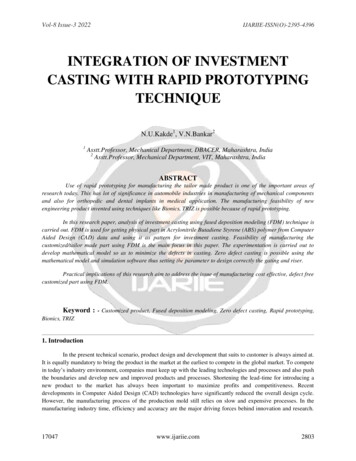
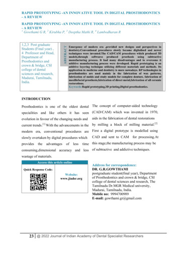
2the cell population [18]. Patient-specific cutting guides madeby rapid prototyping are newly offered to the orthopedicfield to specify the implantation of prostheses, in particularfor knee surgery [19, 20]. The manufacturing of patientspecific knee prostheses made by rapid prototyping forscientific research is still in the early stage. Prototypes madeof metal—for example, manufactured by laser sintering—are still expensive at this moment and require additionaltreatment, such as polishing to achieve surface roughnessrepresentative of the commercial prosthesis. Alternatively,methods such as 3D-printing or molding can be used tocreate polymer prototypes. In particular, 3D-printing is aquick and inexpensive method which allows high geometricalaccuracy. However, the use of polymers rather than metallicalloys results in prototypes of reduced mechanical properties.It is unknown if such materials may be suitable for in vitrotesting, in particular for in vitro knee kinematic studies whichtypically subject the knee joint to reduced body weights for alimited number of loading cycles.This study therefore sought to determine if the use ofrapid prototyped prostheses can serve as an alternative to thestandard prostheses for in vitro studies for knee, in particularfor the study of retropatellar biomechanics.To test this issue, the sliding friction parameters of thestandard bearing combination in TKA (ultrahigh molecularweight polyethylene versus cobalt-chromium alloy) werefirstly measured and compared to the rapid prototype material. Additionally, PTFE was used as a counterpart againstboth femoral component materials in the friction test,because it is often used to protect the pressure sensitive foilagainst shear. The foil is sutured on the patella surface andhas therefore contact with the femoral component [3, 11, 21].Then, in a second step, rapid prototyped femoral components of a commercial prosthesis design were created andimplanted in seven cadaver knee specimens. These weretested in a custom-made dynamic knee rig under standardized conditions while recording retropatellar pressure andknee kinematics, and these measurements were comparedwith the ones obtained for identical tests for standard components made of cobalt chromium in the same knee specimens.BioMed Research InternationalFigure 1: The Columbus CR prosthesis (Aesculap AG, Tuttlingen,Germany; top) and the test pieces (bottom) for the friction test madeof the standard material (CoCr29Mo6) on the left and the rapidprototype material (RGD840) on the right side.Table 1: Material properties of the photopolymer resin.ParameterIngredientsModulus of elasticityTensile strengthElongation to breakShore hardnessRockwell hardnessRGD 840 vero blueSeveral acrylate oligomers; acrylicmonomer; isobornyl acrylate;photoinitiator2000–3000 MPa50–60 MPa15–25%83–86 (Scale D)73–76 (Scale M)size 1000). Finally, a roughness of R𝑎 0.44 𝜇m was reachedfor the surrogates, while the prostheses made of SPM reachedR𝑎 0.05 𝜇m.Tibial insert was made of UHMWPE (GUR 1050).For the ring-on-disc friction test ring-shaped sampleswere produced of SPM and RPM. The discs which wereused as counterparts in the test setup were made of ultrahigh molecular weight polyethylene (UHMWPE) and polytetrafluoroethylene (PTFE; HighTechflon, Konstanz, Germany).2. Materials and Methods2.2. Ring-on-Disc Friction Test2.1. Prostheses and Test Samples. Femoral components of afixed bearing knee prosthesis (Columbus CR, Aesculap, Tuttlingen, Germany) manufactured from casted CoCr27Mo6(standard prostheses material; SPM) and rapid prototypematerial (RPM; RGD 840 vero blue, Stratasys GmbH, Frankfurt) were obtained from the manufacturer (Figure 1). Thematerial specifications of the RPM are shown in Table 1.Original CAD data were used to produce rapid prototypesfor the femoral components in sizes 2 until 5 for each side(left/right knee) with a professional 3D-printer (Object Eden350, Rehovot, Israel). These specimens were printed in thinlayers (down to approximately 50 𝜇m) of a liquid photopolymer resin (Table 1), which immediately polymerized underUV-light. Afterwards the rapid prototyped prostheses werepolished submerged with fine grained sandpaper (up to grain2.2.1. Ring-on-Disc Rig. A tribological test setup according toISO 6474 and Huber et al. was used to measure the frictioncoefficient (𝜇𝑅 ) [22]. The ring (friction area 160.2 mm2 ;radiusexternal 10 mm; radiusinternal 7 mm) rotated periodically with 1 Hz on the disc (diameter 25 mm) with anamplitude of 25 . Axial compression between ring and discwas adjusted with a manually controlled trapezoidal spindle.The compression was measured with a force transducer(HBM, Darmstadt, Germany), while the friction moment wasdetected with a beam using a half bridge strain gauge (HBM,Darmstadt Germany). This moment was converted into aforce by using the geometrical parameters of the specimen(Figure 2). Both sensors were connected to a personal computer using an analog digital converter (compactDAQ withNI 9237 & NI 9236 modules; National Instruments, Austin,
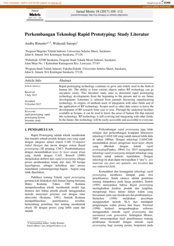
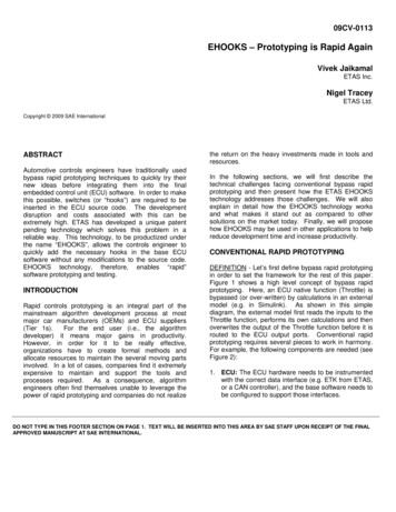
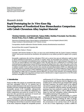
BioMed Research InternationalMF3Ring:(a) SPM(b) RPMDisc:(1) UHMWPE(2) PTFEFAFigure 2: Schematic setting of the ring-on-disc rig with thedemonstration of the axial compression force (𝐹𝐴 ) and the frictiontorque (𝑀𝐹 ) as well as the tested material combinations. The rotationof the ring occurs about the rotation axis, which is identic to the axialload transmission.Table 2: Number of tested specimens subdivided in the fourmaterial combinations; UHMWPE and cobalt-chromium alloy arethe common bearing material for knee arthroplasties; PTFE is notused in vivo but serves protection of the retropatellar pressuresensitive foil during in vitro examinations.Femoral prosthesis materialUHMWPE (femorotibial counterpart)PTFE (patellofemoral counterpart)CoCr27Mo6(SPM)RGD 840vero blue(RPM)𝑛 6𝑛 6𝑛 6𝑛 6USA) and a self-written program code on LabVIEW (Version2011, National Instruments, Austin, USA) to record sensorsdata continuously with a sample rate of 1000 samples persecond.2.2.2. Friction Test. Forty-eight hours before testing, allspecimens were conditioned in a synovial replacement composed of newborn calf serum (S0125; Biochrom AG; Berlin,Germany) diluted with deionized water to reach a proteinconcentration of 30 g/L. Lubrication was secured using thesame fluid during the test. The sliding friction coefficient(friction coefficient) of six specimens per material combination (Table 2) was measured in 250 N steps beginningfrom 500 N to 1500 N axial compression under ambienttemperature. Friction force was measured five times at eachaxial load step. The friction coefficient was calculated bydividing the friction force by the axial force.2.2.3. Statistics. An unpaired 2-way ANOVA (material pairing and axial load) with a Tukey post hoc test was usedto compare each group (SPSS 21, IBM). Significance wasapproved with 𝑃 0.05. Additionally the mean difference(MD) and the confidence intervals (CI) were presented.Figure 3: Knee rig with a mounted specimen with implanted TKA;knee kinematics were measured with an ultrasound markers onfemur, tibia, and patella; by removing the anterior cables, pressuresensitive foil covered with Teflon tape behind the patella andprosthesis were visible (magnification-box).2.3. Knee Rig Investigation2.3.1. Knee Rig. The custom knee rig (Figure 3) simulates aloaded squat with a human specimen using two linear drivesas presented in a previous publication [11]. The first actuatorflexes and extends the knee with a constant velocity. Twoangle sensors (8820 Burster, Gernsbach, Germany) in theupper “hip” and lower “ankle” joint are used to measurethe flexion angle of the knee joint. The second stepperdrive simulates the quadriceps muscle. The resulting forceis measured with miniature force transducers (8417-6002Burster, Gernsbach, Germany) near the tendons. Additionally hamstrings, vastus lateralis, and medialis muscle aresimulated with 2 kg masses. A six degree of freedom forcemoment-sensor measures the ground reaction (FN 7325-31FGP Sensors, Cedex, France).All sensors are amplified up to maximum 10 volts anddigitalized with an 18-bit analog digital converter (PCI 6281National Instruments, Texas, USA). The rig is controlledwith a quad-core personal computer. Four parallel real-timeprogram loops (LabVIEW, Austin, US) for each core arenecessary to control the knee rig, while the first loop acquiresthe sensor data. The second loop is a parabolic PID-forcecontrol loop to hold the ground reaction force constant withthe loaded quadriceps muscle. The third loop controls theflexion and extension of the knee in a constant velocity. Thelast loop writes the sensor data into an ASCII-File.For this study all specimens were tested with a groundreaction force of 50 N, a velocity of 3 /s, and a squat from 20 to 120 flexion and extension back to 20 .Retropatellar pressure distribution (Tekscan, Boston, US)and femorotibial (ap-translation, femorotibial rotation) andpatellofemoral (tilt, rotation, shift defined in [23]) kinematics were acquired during the squat with an ultrasoundthree-dimensional motion analysis system (CMS 20 Zebris,Isny, Germany) ensuring an accuracy of 0.1 mm and 0.1 .
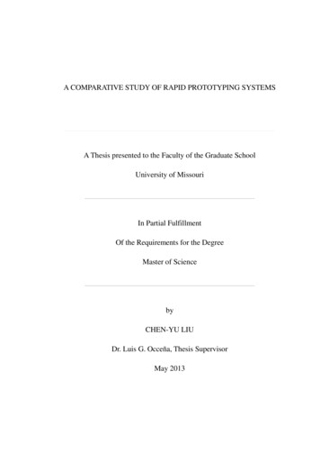
42.3.3. Statistics. Results for the RPM were plotted againstthe SPM results at 5 intervals of flexion angle. A Demingregression was performed for each specimen and each parameter to calculate the slope of the regression line. Equalitycriterion implies a linear regression whose slope is notsignificantly different to 1 using a one sample t-test.3. Results3.1. Coefficient of Sliding Friction of the Ring-on-Disc Test.Both material combination and axial load influence thesliding friction coefficient in the ring-on-disc rig (P 0.001).0.20Coefficient of sliding friction2.3.2. Cadaver Preparation and TKA Implantation. Sevenhuman knees (57.7 13.0 years; 177.7 6.3 cm; 82.4 11.9 kg; 5 males, 2 females) were tested under weight-bearingconditions. The specimens were standardized in length with afemur cut 20 cm proximally and a tibia cut 15 cm distally fromthe epicondyle axis, respectively. The fibula head was fixed onthe tibia using a cortical screw. Muscle and fat tissues werecarefully removed from the tendons and bones. Finger trapswere connected to the tendons and suture wires (Fibrewire,Arthrex, Karlsfeld, Germany) were used to fix the tendon intothe metallic mesh of the traps. The diaphyses of the femur andtibia were embedded into pots with epoxy resin which werethen mounted on the knee rig.A pressure sensor (K4000; Tekscan; Boston, US), protected with an additional thin layer of PTFE-tape (Thickness:125 𝜇m, HighTechflon, Konstanz, Germany), was fixed at thearticulating surface of the patella with sutures (Novosyn,B. Braun, Melsungen, Germany), with the osteophyte ofthe patella previously removed to ensure better contact.Before, the sensor was conditioned for 20 loading cyclesand calibrated with a 2-point calibration line computed bythe measurement software (I-Scan 6.1). The axial pressurefor calibration and conditioning was applied with a materialtesting machine (Zwick Z010, Ulm, Germany).Additionally a tripod of three ultrasound markers wasattached to each bone and anatomic landmarks wereidentified on the specimen to define kinematic pattern inrelation to the coordinate system of each bone.An experienced surgeon (A. S.) implanted the prosthesesas indicated by the manufacturer using a subvastus approachin the tibia first technique. The tibia was resected perpendicular to an intramedullary rod, while a slope of 3 was includedin the inlay. A gauge instrument was used to balance flexionand extension gap. Then, an intramedullary rod was usedto align the femoral component in a 4 –6 valgus rotationrelative to the bone axis of the femur. The femural componentwas then rotated parallel to the anatomical transepicondylaraxis, priorly defined using an inserted K-wire.After implantation the specimens were tested in theknee rig by acquiring pressure and knee kinematics datawithout additional lubrication. Randomized change betweenthe SPM and the RPM prostheses for each specimen allowedtesting the implants consecutively. Between each test cyclethe biological materials were prevented for dehydration byputting saline-soaked scarfs on the surface of the specimen.BioMed Research International0.150.100.050.005007501000Axial load (N)Material pairings:SPM versus UHMWPERPM versus UHMWPE12501500SPM versus PTFERPM versus PTFEFigure 4: Dependence of the coefficient of sliding friction withrising axial load for the tested parameters; whiskers define the 95%confidence interval.With increasing load, a decrease of the friction coefficientwas measured in the four groups (P 0.001). The frictiontest with the bearing partner UHMWPE provided significanthigher friction coefficients than with PTFE (𝑃 0.001;Figure 4). There was no interaction between load and material combination measurable (𝑃 0.52).The material combinations SPM and RPM against PTFEshowed no differences (MD: 0.0068 (CI: 0.0047; 0.018)) inthe friction coefficient (𝑃 0.413). In contrast, there wasa significant difference (MD: 0.013 (CI: 0.025; 0.0016))between the material combinations SPM, respectively, andRPM to UHMWPE (𝑃 0.013). Pairwise comparisonrevealed that the difference between SPM and RPM at 500 N(3.1 MPa) is significantly increased (MD: 0.031 (CI: 0.051; 0.011) 𝑃 0.002). That difference tends to disappear withincreasing axial loads (F 𝐴 750 N MD: 0.019 (CI: 0.039;0.001) 𝑃 0.06; 𝐹𝐴 1000 N MD: 0.011 (CI: 0.031; 0.008)𝑃 0.3; F 𝐴 1500 N MD: 1.5 10 5 (CI: 0.020; 0.020) 𝑃 1.0;Table 3).3.2. Knee Rig Study. For each measured specimen and eachparameter, a linear regression was calculated by Demingregression. Figure 5 represents a typical result obtained forquadriceps load measured for one specimen with both typesof implant materials.No significant differences were measured in the kneerig between the two tested materials (Table 4). A maximumquadriceps load of 647 131 N with RPM and 620 88 N withSPM was necessary to extend the cadaver knee and causedcomparable results during the whole cycle (𝑃 0.69). Furthermore the maximum retropatellar peak pressure of 6.92 2.01 MPa with RPM and 6.83 1.79 MPa with SPM showedno significant differences (𝑃 0.53). Little deviations couldbe noticed at the maximum of the contact area (Figure 6).RPM showed a tendency to a higher contact area with 402 63 mm2 compared to the SPM with a maximum contact area
BioMed Research International5Slope: 1.043 0.03158SPMQuadriceps load 120F100F80F60F40F200Flexion angle in ( )(a)400600200Quadriceps load (N)RPM800(b)F20F40Flexion angle in ( s load (N)RPM800(c)Figure 5: The left plot shows the quadriceps load in N against the flexion angle of the SPM and the plot at the bottom shows the flexion angleagainst the quadriceps load of the RPM. The diagram in the center is a projection of both plots and compares the RPM material (𝑦-axis) andthe SPM (𝑥-axis). Angles are identified in the upper right corner plot with flexion (F), extension (E) angle. The Deming-regression line withslope and standard deviation of the slope (crosses) are shown.of 380 61 mm2 . However, the change in contact area wasnot significant (𝑃 0.31). Similar behaviors between theRPM and the SPM in terms of kinematics of the femorotibialjoint were depicted. Equivalent results of the patellar tiltof 4.95 1.93 with RPM and 4.87 1.86 with SPM aswell as the patellar rotation of 5.29 3.72 with RPM and5.13 3.47 with SPM could be obtained. The measurementof the lateral shift of the patella provided an average value of4.87 mm (SPM 2.0 mm; RPM 2.2 mm) for both materials.4. DiscussionPrototype constructions used in cadaver studies providea useful way to investigate the biomechanical interactionbetween the patellofemoral and tibiofemoral joints separatelyafter TKA. For research purposes Walker et al. producedseveral types of polymer prostheses by stereolithography [24].Any validation of these prototypes and the proof of a similarbiomechanical behavior compared to original prosthesis werenot included in these studies. However, so far little is knownabout differences that may occur between standard implantmaterials and rapid prototype polymers in biomechanicalstudies at the knee joint. Our study is the first to demonstratethat prostheses made from RPM behave comparably tooriginal prostheses in the knee rig.Our study goal was to evaluate the usability of polymer rapid prototypes compared to the standard cobaltchromium alloy prostheses for patellofemoral joint research.
6BioMed Research International5 MPaLateralLateralRPMSPMFigure 6: Retropatellar pressure distribution of both prosthesis materials (left: rapid prototype material; right: standard prosthesis material)at a flexion angle of 120 in one representative specimen.Table 3: Descriptive statistics of the friction coefficients with standard deviation of the tested material combinations at different axial loads(axial pressure).Axial load (pressure)500 N (3.1 MPa)750 N (4.7 MPa)1000 N (6.2 MPa)1250 N (7.8 MPa)1500 N (9.4 MPa)SPM versus UHMWPE0.099 0.0150.093 0.0250.080 0.0180.073 0.0200.065 0.017RPM versus UHMWPE0.130 0.0350.111 0.0340.091 0.0290.078 0.0250.065 0.021Table 4: Calculated slope by Deming-regression for the tests withSPM and RPM in the knee rig. Additionally the results of the 𝑡test against the slope of 1, which represents an identical behaviorbetween both materials.ParameterSlope with standard deviation 𝑃 valueQuadriceps force1.014 0.0860.69Retropatellar peak pressure0.977 0.0910.53Contact area1.051 0.0120.30ap-translation1.086 0.2070.31Femorotibial rotation0.956 0.1380.43Shift of the patella1.081 0.1690.25Tilt of the patella0.960 0.1760.57Rotation of the patella1.057 0.2430.57We expected first that the friction coefficients of bothstandard prosthesis material and rapid prototype materialin different combinations of counterface material couplingwere not different. Second, we expected that, for the weightbearing loads typically involved in in vitro kinematic testingof the knee, the rapid prototyped materials may provide resultof motion patterns and patella-contact forces, which are notsignificantly different from the standard clinical materials.Our study results do not validate our first hypothesis.Whereas significant differences of the friction coefficient ofthe patellofemoral material combinations (PTFE) were notfound, there were significant differences of SPM and RPMcombinations with UHMWPE as counterface at a low axialload of 500 N (𝑃 0.031). With increased axial pressure,however, the friction coefficient of both materials againstSPM versus PTFE0.063 0.0050.053 0.0050.043 0.0040.038 0.0040.032 0.003RPM versus PTFE0.059 0.0110.044 0.0110.036 0.0100.030 0.0080.026 0.005UHMWPE converged until no difference was measurable at1500 N (𝑃 1). This difference might be a result of the highersurface roughness of the surrogates compared to original one.Our second hypothesis was validated by tests in the kneerig. Indeed, comparable behaviors of SPM and RPM forthe analyzed parameters were observed. Based on this, webelieve that the tested RPM may be suitable for the in vitrotesting of prostheses and the kinematical analyses in theknee rig, despite friction differences with standard prosthesismaterials at low loads, when used in combination withUHMWPE.A few limitations must be accounted in analyzing ourresults which may affect the validity of our conclusionsto other study contexts. First, the measured coefficient offriction of material combinations depends on an amountof parameters: surface roughness, the used lubrication, thevelocity, and the used axial load [25–29]. Small differencescan also be obtained with the use of different friction rigs. Inthis study a rebuilt ring-on-disc simulator according to ISO6474 was used, which simulated a radial sliding of a ring on adisc. On the other hand, studies such as the ones from Saikkowere based on a pin-on-disc-test rig, while Wang et al. useda rig where the coefficient of friction was measured in a totalhip prosthesis.For each material combination a consistent reduction ofthe coefficient of friction was documented while increasingaxial load. This obtained behavior was supported by Saikkoand Wang et al. [30, 31]. Both of them determined anexponential decrease of the sliding friction coefficient ofUHMWPE compared to cobalt-chrome alloy by increasingloads (Table 5).
BioMed Research International7Table 5: Load-dependent friction coefficient of UHMWPE againstCoCr-alloy compared to references; the coefficients of friction werecalculated from the determined exponential formulas of publications.Pressure3.1 MPa4.7 MPa6.2 MPa7.8 MPa9.4 MPaPresent study0.0990.0930.0800.0730.065Saikko [30]0.1580.1190.0990.0840.074Wang et al. [31]0.0830.0630.0520.0440.039To avoid shear forces in the sensitive pressure film, manyworkgroups covered the film with PTFE-tape [3, 11, 21].Therefore the cartilage of the patella was replaced by aPTFE foil which has a friction coefficient ranging between0.03 and 0.06 against SPM. Friction measurements on hiphemiprostheses showed similar friction coefficients between0.02 and 0.11 for cartilage against surgical steel [32] and0.02 up to 0.2 and 0.02 to 0.38 compared to cobalt-chromealloy [33, 34]. However, such differences may not affect ourconclusions in the current study design, as both prosthesismaterials were subjected to similar testing conditions.A second limitation comes from testing conditions inthe knee rig. A small ground load was used in the knee rig,which may be a limitation for extrapolating our results tostudies where higher loads would be simulated. However,Müller et al. and Victor et al. showed that reduced loadsresulted in an amplitude change but do not alter the progression of the measured data [35, 36]. The simplified testingconditions and lower loading magnitudes therefore reducethe material requirements needed for the in vitro testingof knee prostheses. Biomechanical aspects such as wear,mechanical, and fatigue resistance as well as biocompatibilityare minorly relevant for kinematic tests with human cadaverknees. However, differences in friction behavior can alterkinematics and contact behavior in the specimen. Therefore itis important that the results of the knee rig study affirm both,the same intra-articular pressure and knee kinematics by theuse of rapid prototyped and standard prostheses material.A third limitation is that both RPM and SPM materialswere compared in only seven knee specimens. From statistical point of view, the number of specimens tested mightnot fully exclude a type II error. Thereby, the number ofspecimens is comparable to other studies [11, 14, 36–39].The usage of a single knee prosthesis design with a ratherflat-shaped trochlea can also be a forth limitation in ourstudy. Therefore the generalized transfer of these results toother knee replacement systems is not possible. Moreoveronly the typical material of the described 3D-printer couldbe analyzed, so the transferability to other printable materialsand surface roughness is restricted. Despite these limitations,we believe that our pilot study successfully demonstrated thevalidity of using rapid prototype implants made of polymersas surrogates in kinematic testing of the knee. There aremany benefits to using prototyped knee prosthesis for in vitrostudies. Firstly, a separately biomechanical examination of thefemorotibial and patellofemoral joint is possible. Secondly,different prostheses can be implanted on the same bone cuts,which enable quick and accurate change of the componentwithout additional bone resections. Thirdly, different prosthesis alignments are feasible with the use of the same bonecuts, by modification of the articulating surface geometryonly. Fourthly, a test of different prototypes in the samespecimen is possible without reoperation and therefore, dueto the paired observations, fewer specimens may be necessaryto reach the same statistical outcome.5. ConclusionThis pilot study showed that knee prostheses producedfrom rapid prototype polymer can produce knee kinematicsand retropatellar pressure distributions comparable to thoseobtained with original knee prostheses in the knee rig.Therefore it is possible to use this technique to get more comprehension of TKA biomechanics. Furthermore, consecutivebiomechanical analyses of various knee prostheses designscould be analyzed in the same knee without any reoperationof the joint in vitro. Future studies will focus on modifyingimplant orientations for better understanding of the effectsof malignment on patellofemoral joint mechanics and therelation to pain experienced by patients.Conflict of InterestsThe authors declare that there is no conflict of interestsregarding the publication of this paper.AcknowledgmentsThe authors would like to thank Thomas Hagen (AesculapAG) for providing the CAD-data of the knee prosthesis andPaul Fecht (Aesculap AG) for the production of the rapidprototypes and finally they thank Dr. Alexander Crispin(Institute of Biometry and Epidemiology, LMU Munich) forhis statistical council.References[1] R. B. Bourne, B. M. Chesworth, A. M. Davis, N. N. Mahomed,and K. D. J. Charron, “Patient satisfaction after total kneearthroplasty: Who is satisfied and who is not?” ClinicalOrthopaedics and Related Research, vol. 468, no. 1, pp. 57–63,2010.[2] W. Hauf, T. Mittlmeier, F.-W. Hagena, and W. Plitz, “In vivomeasurement of the intra-osseous pressure of
er total knee arthroplasty (TKA) such as anterior knee pain and subluxations might be related to altered patellofemoral biomechanics, in particular to trochlear design and femorotibial joint positioning. A method was developed to test femorotibial and patellofemoral joint modi cations separately with D-rapid prototyped components for in vitro tests, but material di erences may further in uence .