Transcription
Presentation forRAPID PROTOTYPING TEHNOLOGIESDEPARTMENT OF MECHANICAL ENGINEERINGM.TECH : I SEMbyDr.G.V.R.Seshagiri Rao
UNIT-1 : INTRODUCTION TO RAPID PROTOTYPING1. Fundamentals of Rapid Prototyping2. Rapid Prototyping Technologies3. Applications and Benefits of Rapid Prototyping2
RAPID PROTOTYPING3
Rapid Prototyping (RP)A family of fabrication processes developed to makeengineering prototypes in minimum lead time based on a CADmodel of the item .Traditional method is machining Can require significant leadtimes – several weeks, depending on part complexity anddifficulty in ordering materials.RP allows a part to be made in hours or days, given that acomputer model of the part has been generated on a CADsystem4
RP – Two Basic Categories:1. Material removal RP - machining, using a dedicated CNCmachine that is available to the design department on shortnotice– Starting material is often wax Easy to machine Can be melted and resolidified– The CNC machines are often small - called desktopmachining2. Material addition RP - adds layers of material one at a time tobuild the solid part from bottom to top5
Starting Materials in Material Addition RP1. Liquid monomers that are cured layer by layer into solidpolymers2. Powders that are aggregated and bonded layer by layer3. Solid sheets that are laminated to create the solid partAdditional Methods In addition to starting material, the various materialaddition RP technologies use different methods of buildingand adding layers to create the solid part There is a correlation between starting material and partbuilding techniques6
Steps to Prepare Control Instructions1. Geometric modeling - model the component on a CAD systemto define its enclosed volume2. Tessellation of the geometric model - the CAD model isconverted into a computerized format that approximates itssurfaces by facets (triangles or polygons)3. Slicing of the model into layers - computerized model is slicedinto closely-spaced parallel horizontal layers7
UNIT –II: TYPES OF PROTOTYPING SYSTEMSClassification of RP Technologies There are various ways to classify the RP techniques thathave currently been developed The RP classification used here is based on the form of thestarting material:1. Liquid-based2. Solid-based3. Powder-based8
Liquid-Based Rapid Prototyping Systems Starting material is a liquid About a dozen RP technologies are in this category Includes the following processes:– Stereolithography– Solid ground curing– Droplet deposition manufacturing9
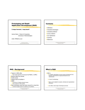
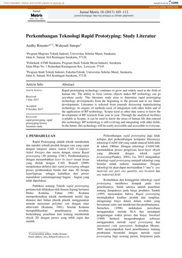
Stereolithography (STL)RP process for fabricating a solid plastic part out of aphotosensitive liquid polymer using a directed laser beam tosolidify the polymer Part fabrication is accomplished as a series of layers - eachlayer is added onto the previous layer to gradually build the 3D geometry The first addition RP technology - introduced 1988 by 3DSystems Inc. based on the work of Charles Hull Moreinstallations than any other RP method10
StereolithographyFigure 1.0 Stereolithography: (1) at the start of the process, inwhich the initial layer is added to the platform; and (2) afterseveral layers have been added so that the part geometrygradually takes form.11
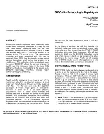
Solid Ground Curing (SGC)Like stereolithography, SGC works by curing a photosensitivepolymer layer by layer to create a solid model based on CADgeometric data Instead of using a scanning laser beam to cure a given layer,the entire layer is exposed to a UV source through a maskabove the liquid polymer Hardening takes 2 to 3 s for each layer12
Solid Ground CuringFigure 2.0 SGC steps for each layer: (1) mask preparation, (2)applying liquid photopolymer layer,(3) mask positioning andexposure of layer, (4) uncured polymer removed from surface,(5) wax filling, (6) milling for flatness and thickness.13
Facts about SGC Sequence for each layer takes about 90 seconds Time to produce a part by SGC is claimed to be about eighttimes faster than other RP systems The solid cubic form created in SGC consists of solid polymerand wax The wax provides support for fragile and overhanging featuresof the part during fabrication, but can be melted away later toleave the free-standing part14
Droplet Deposition Manufacturing (DDM)Starting material is melted and small droplets are shot by anozzle onto previously formed layer Droplets cold weld tosurface to form a new layer Deposition for each layer controlled by a moving x-y nozzlewhose path is based on a cross section of a CAD geometricmodel that is sliced into layers .Work materials include waxand thermoplastics15
Solid-Based Rapid Prototyping Systems Starting material is a solid Solid-based RP systems include the following processes:– Laminated object manufacturing– Fused deposition modeling16
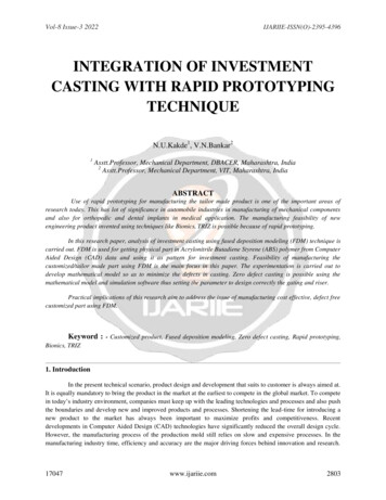
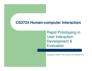
Laminated Object Manufacturing (LOM)Solid physical model made by stacking layers of sheet stock,each an outline of the cross-sectional shape of a CAD modelthat is sliced into layers Starting sheet stock includes paper, plastic, cellulose, metals,or fiber-reinforced materials The sheet is usually supplied with adhesive backing as rollsthat are spooled between two reels After cutting, excess material in the layer remains in place tosupport the part during building17
Laminated Object ManufacturingFigure 34.5 Laminated object manufacturing.18
UNIT-III : Powder-Based RP Systems Starting material is a powder Powder-based RP systems include the following:– Selective laser sintering– Three dimensional printing19
Selective Laser Sintering (SLS)Moving laser beam sinters heat-fusible powders in areascorresponding to the CAD geometry model one layer at a timeto build the solid part After each layer is completed, a new layer of loose powders isspread across the surface Layer by layer, the powders are gradually bonded by the laserbeam into a solid mass that forms the 3-D part geometry In areas not sintered, the powders are loose and can bepoured out of completed part20
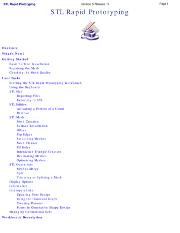
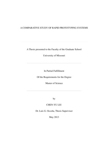
Three Dimensional Printing (3DP)Part is built layer-by-layer using an ink-jet printer to ejectadhesive bonding material onto successive layers of powders Binder is deposited in areas corresponding to the crosssections of part, as determined by slicing the CAD geometricmodel into layers The binder holds the powders together to form the solid part,while the unbonded powders remain loose to be removedlater To further strengthen the part, a sintering step can be appliedto bond the individual powders21
Three Dimensional PrintingFigure. Three dimensional printing: (1) powder layer isdeposited, (2) ink-jet printing of areas that will becomethe part, and (3) piston is lowered for next layer (key: v motion).22
RP Applications Applications of rapid prototyping can be classified into threecategories:1. Design2. Engineering analysis and planning3. Tooling and manufacturing23
Design Applications Designers are able to confirm their design by building a realphysical model in minimum time using RP Design benefits of RP:– Reduced lead times to produce prototypes– Improved ability to visualize part geometry– Early detection of design errors– Increased capability to compute mass properties24
Problems with Rapid Prototyping Part accuracy:– Staircase appearance for a sloping part surface due tolayering– Shrinkage and distortion of RP parts Limited variety of materials in RP– Mechanical performance of the fabricated parts is limitedby the materials that must be used in the RP process25
Rapid Prototyping SystemsThe term rapid prototyping (RP) refers to a class of technologiesthat can automatically construct physical models from ComputerAided Design (CAD) data.These "three dimensional printers" allow designers to quicklycreate tangible prototypes of their designs, rather than just twodimensional pictures.26
– Most prototypes require from three to seventy-two hours tobuild, depending on the size and complexity of the object.– This may seem slow, but it is much faster than the weeks ormonths required to make a prototype by traditional meanssuch as machining.– These dramatic time savings allow manufacturers to bringproducts to market faster and more cheaply.27
Rapid Prototyping Systems Such models have numerous uses:– Excellent visual aids for communicating– Prototypes can be used for design testing.– Used to make tooling– Used to make production-quality parts28
All RP techniques employ the same basic five-step process.1.2.3.4.5.Create a CAD model of the designConvert the CAD model to STL format (stereo lithography)Slice the STL file into thin cross-sectional layersConstruct the model one layer atop anotherClean and finish the model29
CAD Model Creation:– First, the object to be built is modeled using a Computer-AidedDesign (CAD) software package.– Solid modelers, such as Pro/ENGINEER, tend to represent 3-Dobjects more accurately than wire-frame modelers such asAutoCAD, and will therefore yield better results.– This process is identical for all of the RP build techniques.30
Conversion to STL Format:– To establish consistency, the STL (stereo lithography, the firstRP technique) format has been adopted as the standard ofthe rapid prototyping industry.– The second step, therefore, is to convert the CAD file into STLformat. This format represents a three-dimensional surface asan assembly of planar triangles– STL files use planar elements, they cannot represent curvedsurfaces exactly. Increasing the number of triangles improvesthe approximation31
Slice the STL File:– In the third step, a pre-processing program prepares the STLfile to be built.– The pre-processing software slices the STL model into anumber of layers from 0.01 mm to 0.7 mm thick, dependingon the build technique.– The program may also generate an auxiliary structure tosupport the model during the build. Supports are useful fordelicate features such as overhangs, internal cavities, andthin-walled sections.32
Layer by Layer Construction:– The fourth step is the actual construction of the part.– RP machines build one layer at a time from polymers, paper,or powdered metal.– Most machines are fairly autonomous, needing little humanintervention.33
Clean and Finish:– The final step is post-processing. This involves removing theprototype from the machine and detaching any supports.– Some photosensitive materials need to be fully cured beforeuse– Prototypes may also require minor cleaning and surfacetreatment.– Sanding, sealing, and/or painting the model will improve itsappearance and durability.34
Fused Deposition Modeling (FDM) is a solid-based rapid prototyping method that extrudesmaterial, layer-by-layer, to build a model. A thread of plastic is fed into an extrusion head, where it isheated into a semi-liquid state and extruded through a very smallhole onto the previous layer of material. Support material is also laid down in a similar manner.35
Advantages of FDM Process High strength Cost-effective Waterproof ABS material Multiple material colors36
FDM 2000 Specifications Build Volume: 10" x 10" x 10" Materials:ABS, Casting Wax Build Step Size: 0.005" to 0.030"Prodigy SpecificationsBuild Volume: 8" x 8" x 10"Materials: ABS, Casting WaxBuild Step Size: 0.007", 0.010", 0.013"Up to 4x faster than the FDM 2000Fused Deposition Modeling37
Examples ofFused Deposition Modeling38
Laminated Object Manufacture As the name implies the process laminates thin sheets of film(paper or plastic) The laser has only to cut/scan the periphery of each layer39
The process:– The build material (paper with a thermo-setting resin glue onits under side) is stretched from a supply roller across an anvilor platform to a take- up roller on the other side.– A heated roller passes over the paper bonding it to theplatform or previous layer.– A laser, focused to penetrate through one thickness of papercuts the profile of that layer. The excess paper around andinside the model is etched into small squares to facilitate itsremoval.40
The process continued:– The process of gluing and cutting continuous layer by layeruntil the model is complete.– To reduce the build time, double or even triple layers arecut at one time which increases the size of the steps oncurved surfaces and the post processing necessary tosmooth those surfaces.41
Applications of LOM objects:– LOM objects are durable, multilayered structures which canbe machined, sanded, polished, coated and painted.– Used as precise patterns for secondary tooling processes suchas rubber moulding, sand casting and direct investmentcasting.– Used for limited testing.– Used as visual models.42
43
Examples of Laminated Object Manufacture Wind Turbine– In this case the LOM processwas initially used to checkthe CAD geometry:subsequently the model wasused as a sand castingpattern. The picture oppositeshows 5 identical bladesassembled around an SLAhub.44
A LOM model was built for acustomer who required aprototype to test the fit andoperation of internal componentsin an electrical housing.45
Prototype: It is a model fabricated to prove out a concept oran idea. Solid Modelling: It’s a branch of CAD that produces 2D or 3Dobjects in an electronic format.46
Rapid prototyping is basically a additive manufacturingprocess used to quickly fabricate a model of a part using 3-DCAM data. It can also be defined as layer by layer fabrication of 3Dphysical models directly from CAD.47
Need for Rapid Prototyping To increase effective communication.To decrease development time.To decrease costly mistakes.To minimize sustaining engineering changes.To extend product life time by adding necessary features &eliminating redundant features early in the design.48
Increasing the no of variants of products.Increase in product complexity.Decrease in product lifetime before obsolescence.Decrease in delivery time.Product development by Rapid prototyping by enabling bettercommunication.49
Conventional Machining Its not suitable for complex shapes because they are difficultto machine. Time consuming Very costly Tedious or very laborious. Skilled operator is required. Accuracy will be less. Increased product development time.50
Pre-processing:- CAD model slicing & setting algorithms appliedfor various RP systems Post-processing:-Cleaning operations required to finish a partafter removing it from RP machine. Materials for Rapid Prototyping: Paper, Wax, Plastics, Resins,Metallic powders.51
Methodology of Rapid Prototyping Construct a CAD model.Convert it to STL format.RP machine processes .STL file by creating sliced layers of model.First layer of model is created.Model is then lowered by thickness of next layer.Process is repeated until completion of model52
The model & any supports are removed. Surface of the model is then finished and cleaned.53
54
55
56
57
UNIT-IV : RAPID PROTOTYPING DATA FORMATSoftware SLA CONTROL AND SET UP SOFTWARE: It operates on SLA250 and SLA 500 machines. It has got three packages. a) SLA VIEW: UNIX based system for viewing and positioning. b) BRIDGE WORKS: UNIX based software for generatingsupport structures.58
c) SLA SLICE: Slicing and system operation software. MAESTRO: UNIX based software MS WINDOWS NT SOFTWARE (3D LIGHT YEAR): It isused for viewing, positioning, support generation and slicing,build station for operating SLA machine.59
Build Materials Used:– Epoxy Resin, Acrylate Resin– Epoxy Resin has better material properties and lesshazardous but require large exposure time for curing.60
SLA Hardware A removable VAT that holds the build resin. A detachable perforated build platen on a Z axis elevatorframe An automated resin level checking apparatus VAT has a small amount of Z movement capability whichallows computer to maintain a exact height per layer.61
A recoated blade rides along the track at the top of the rackand serves to smooth the liquid across the part surface toprevent any rounding off edges due to cohesion effects. Some systems have Zaphyr recoater blade which actuallysoftens up resin and delivers it evenly across the part surface. Behind the build chamber resides the laser and optics requiredto cure resin. Laser unit is long rectangular about 4 feet long and remainsstationary.62
63
64
65
66
67
Stereolithography68
Stereolithography Apparatus Operation The process begins with the solid model in various CADformats The solid model must consist of enclosed volumesbefore it is translated form CAD format into .STL FILE The solid model is oriented into the positive octant ofCartesian co-ordinate system and then translate out Zaxis by at least 0.25 inches to allow for building ofsupports69
The solid model is also oriented for optimum build whichinvolves placing complex curvatures in XY plane where possibleand rotating for least Z height as well as to where least amount ofsupports are required. The .STL FILE is verified.70
The final .STL FILE one which supports in addition to original fileare then sliced into horizontal cross sections and saved as slicefile. The slice files are then masked to create four separate files thatcontrol SLA machine ending with 5 extensions L, R, V and PRM.71
Important one is V file. I.e. Vector file. The V file containsactual line data that the laser will follow to cure the shape ofthe part. R file is the range file which contains data for solid or openfields as well as re-coater blade parameters.72
The four build files are downloaded to SLA which beginsbuilding supports with platen adjust above the surface level.The first few support layers are actually cured intoperforations into platen, thus providing a solid anchor for therest of the part.73
By building, SLA uses laser to scan the cross section and fillacross the surface of resin which is cured or hardened into thecross sectional shape. The platen is lowered as the slices are completed so that moreresin is available in the upper surface of the part to be cured.Final step is Post Processing.74
Post Processing:Ultraviolet Oven (Post Curing Apparatus)An Alcohol Bath.Clean the part in the alcohol bath and then go for final curing.75
Advantages:– Parts have best surface quality– High Accuracy– High speed– Finely detailed features like thin vertical walls, sharp corners& tall columns can be fabricated with ease. Disadvantages:– It requires Post Processing. i.e. Post Curing.– Careful handling of raw materials required.– High cost of Photo Curable Resin.76
Applications:– Investment Casting.– Wind Tunnel Modeling.– Tooling.– Injection Mould Tools.77
78
Selective Laser Sintering(SLS)79
DTM sinter station 2500 is the machine used for the process. Selective Laser Sintering begins like most other rapidprototyping processes with a standard . STL CAD file format. DTM view software uses the .STL files.This software do the required orientation and scaling of parts. This machine has auto nesting capabilities which will placemultiple part optimally in the build chamber for bestprocessing speed and results. Once the .STL file is placed andparameters are set the model is directly built from the file.80
Principle of Operation81
The sinter station has build piston at the center and feedpiston on the either side. The model is built layer by layer like other rapid prototypingprocess so that the build piston will begin at the top of itsrange and will lower in increments of the set layer size asparts are built. With the build piston at the top a thin layer of powder isspread across the build area by the roller from one of the feedpiston. The laser then cures in a raster sweeps motion acrossthe area of the parts being built.82
The part piston lowers and more powder is deposited and theprocess is continued until all of the part is built. The build media is removed from the machine. It is a cake ofpowder. This cake is taken to the breakout station where excesspowder is removed from the part manually with brushes.83
The excess powder that has been removed can be kept forrecycling and can be reused. Some material needs additional finishing. Some of thefinishing techniques include grid blasting, sanding, polishing,drilling, taping and coating .84
Purpose of Selective Laser Sintering:– To provide a prototyping tool– To decrease the time and cost of design to product cycle.– It can use wide variety of materials to accommodatemultiple application throughout the manufacturingprocess.85
86
Applications:1. As conceptual models.2. Functional prototypes.3. As Pattern masters.87
Advantages:1. Wide range of build materials.2. High throughput capabilities.3. Self supporting build envelop.4. Parts are completed faster.5. Damage is less.6. Less wastage of material.88
Disadvantages:1. Initial cost of system is high.2. High operational and maintenance cost.3. Peripheral and facility requirement.89
Fused Deposition Modeling90
Introduction: Fused Deposition Modeling is an extrusion based rapidprototyping process although it works on the same layer bylayer principle as other RP systems. Fused Deposition Modeling relies on standard STL data filefor input and is capable of using multiple build materials ina build or support relationship.91
Software Used: FDM machine uses Quick Slice software to manipulate andprepare the incoming STL data for use in FDM machines.Software can be operated on various types of workstations fromUNIX to PC based.92
Build Materials: Investment Casting Wax. Acrilonitrile Butadine Styrene plastic. Elastomer.Extrusion Head :It is a key to FDM technology.Compact and removable unit.It consists of Drive Blocks, Heating Chamber and Tips.93
94
95
Drive Blocks: These are raw material feeding mechanisms and aremounted on back of head . These are computercontrolled. Capable of precision loading and unloading of filament. It consists of two parallel wheels attached to a smallelectric motor by gears. The wheels have a plastic and rubber thread and arespaced approximately 0.07inches apart and turn oppositeto one another.96
When the wheels are turned in and end of the filament isplaced between them, they continue to push or pull thematerial depending on direction of rotation. When loading the filament is pushed horizontally into thehead through a hole, a little larger than the filament diameterwhich is the entry to the heating chamber.97
Heating chamber It is a 900 curved elbow wrapped in a heating element whichserves two primary functions:– To change the direction of the filament flow so that thematerial is extruded vertically downwards.– To serve as a melting area for the material The heating element is electronically controlled and hasfeedback thermocouple to allow for a stable temperaturethroughout.98
The heating elements are held at a temperature justabove the melting point of the material so that thefilament passes from the exit of the chamber is in moltenstate. This allows for smooth extrusion as well as timecontrol on material placement. At the end of the heating chamber which is about 4 inchlong is the extrusion orifice or tip. The two tips are externally threaded and screwed up intothe heating chamber exit and are used to reduce theextruded filament diameter to allow for better detailedmodeling. The tips are heated by heating chamber up to above themelting point of the material.99
The tips can be removed and replaced with different sizeopenings, the two most common being 0.012 inch and 0.025inches. The extruding surface of the tip is flat serving as the hot shearingsurface to maintain a smooth upper finish of extruded material. The tip is the point at which the material is deposited onto afoam substrate to build the model. The foam substrate is an expendable work table on which partsare built. The substrate is about 1 inch thick and is passed on into aremovable tray by one quarter inch pins.100
UNIT-V :RAPID PROTOTYPING APPLICATIONS101
102
103
104
Aerospace IndustryWith the various advantages that RP technologies promise, it isonly natural that high value added industries like the aerospaceindustry have taken special interest in it even though initialinvestment costs may be high.Bio-Medical applications From Manufacturing of medical devices and customizedimplants and prostheses to surgical planning and education,RPcan be applied to enhance medical applications and health caredelivery.105
106
107
THANK YOU108
Rapid Prototyping Systems The term rapid prototyping (RP) refers to a class of technologies that can automatically construct physical models from Computer-Aided Design (CAD) data. These "three dimensional printers" allow designers to quickly create tangible prototypes of their designs, rather than just two-dimensional pictures. 26