Transcription
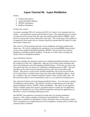
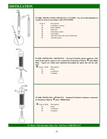
Aspen Tutorial #6: Aspen DistillationOutline: Problem DescriptionAspen Distillation OptionsDSTWU DistillationRadFrac DistillationProblem Description:A mixture containing 50.0 wt% acetone and 50.0 wt% water is to be separated into twostreams – one enriched in acetone and the other in water. The separation process consistsof extraction of the acetone from the water into methyl isobutyl ketone (MIBK), whichdissolves acetone but is nearly immiscible with water. The overall goal of this problem isto separate the feed stream into two streams which have greater than 90% purity of waterand acetone respectively.This week we will be learning about the various distillation calculation methods thatAspen uses. We will be completing the separation of our acetone/MIBK streams basedon one of the simplified distillation methods, DSTWU and one of the more rigorousdistillation calculation methods, RadFrac. From this we will be able to compare theresults of the two distillation methods.Aspen Distillation Options:Aspen has multiple unit operations options for completing distillation problems, based onthe complexity of the user’s application. Open up your existing Aspen simulation andclick on the Separators tab in the Equipment Model Library. In this tab you will see thefirst option that users can choose for completing a distillation process, SEP2. This unitoperation can be used to model separation processes with only two possible outletstreams. This process can be used to simulate distillations, but it does not provide thelevel of detail that is available when using some of the other distillation options. Somekey variables it does not consider include the number of trays and the reflux ratio. Forthis reason this option is not recommended except as a very general screening process.Now select the Columns tab in the Equipment Model Library. You will notice a numberof distillation column options. This tutorial will focus on introducing you to the threegeneral distillation choices, DSTWU, Distl, and RadFrac. The other six unit operationchoices complete much more rigorous calculations than we require for our applicationand they are intended for use in more difficult separations and specific applications (i.e.PetroFrac is used in simulating refining processes).The DSTWU unit operation is designed for single feed, two product distillationprocesses. This column completes calculations using Gilliland’s, Winn’s, andUnderwood’s methods for calculations of stages and reflux ratios as indicated in Table 1.These calculations are completed based on two assumptions, constant molar overflow andconstant relative volatilities.52
Aspen Tutorial #6Table 1: DSTWU Calculation MethodsShortcut MethodCalculates For:WinnMinimum number of stagesUnderwoodMinimum reflux ratioGillilandRequired reflux ratio for a specified number of stagesor required number of stages for a specified reflux ratioFor a specified product recovery (both light and heavy), the DSTWU column firstestimates the minimum number of stages and the minimum reflux ratio, and then itcalculates the either the required reflux ratio or the required number of theoretical stagesbased on the user input. During these calculations, Aspen will also estimate the optimumfeed stage location and the condenser and reboiler duties. Finally, when the calculationsare complete, Aspen can produce tables and plots of the reflux ratio/stage profile. Whencompleting complicated simulations later in your career, you could use this column to geta quick idea about a process, and use its results as inputs to a more detailed simulation.The Distl unit operation is also designed for a single feed, two product distillationprocess. However, this column calculates product compositions based on the Edmisterapproach. Again, the calculations are completed based on the assumptions of constantmolar overflow and constant relative volatilities. The user is required to input a numberof the column specifications with this unit operation, including the number of stages, thereflux ratio, and the distillate to feed ratio. We will not be using this option.The final general distillation unit operation is the RadFrac column. This distillation unitcompletes much more rigorous calculations than the other two methods and can be usedto simulate absorption, stripping, extractive distillation, and azeotropic distillation forsolids, liquids, and gases. This column can also be used for highly non-ideal liquidsolutions or processes with an on-going chemical reaction. Finally, the RadFrac columncan have multiple feed and product streams (including pump-around streams) and it cansimulate columns with trays, random packing, or structured packing. As you can see, thisdistillation option is much more complicated than the previous two methods, and we willbe covering this method in more depth as we input the data for it.DSTWU Distillation:In the last Aspen homework, we adjusted our design specification input in Tutorial #5 toachieve a water purity of 95%. We will keep this updated specification in our ongoingsimulation, so if you did not complete the homework two weeks ago, do so now.The first update we will make to our simulation is the addition of another mixer. Add ina new mixer which combines the two streams of acetone and MIBK from the two flashseparators that we added in the previous tutorials. This can be seen in the processflowsheet window shown in Figure 1.53
Aspen Tutorial #6Figure 1: Acetone/MIBK MixerAt this point save your Aspen simulation under two names. We will use one version tocomplete a distillation with the DSTWU distillation column and we will use the otherversion to complete the simulation with the RadFrac column. I would suggest savingthem with names that indicate which distillation method is being used.Now select the Columns tab in the Equipment Model Library and place a DSTWUcolumn into the process flowsheet window. Connect the product stream from the newmixer to the DSTWU column and add in two product streams where Aspen indicates theyare required. We will also be adding in a third product stream off of the condenser, toaccount for any free water product that can be separated from within the condenser.Rename the streams and column as you see fit. At this point your flowsheet should looksimilar to that in Figure 2.54
Aspen Tutorial #6Figure 2: Completed Process FlowsheetNow open up the Data Browser window. You will notice that we are only required toupdate our data input in the Blocks tab. Under the appropriate option for the new mixer,input a mixing temperature and pressure of 75º F and 50 psi. Then open up theappropriate option for the distillation column. The input window is shown below inFigure 3.55
Aspen Tutorial #6Figure 3: DSTWU Data Input WindowFor this simulation we will be inputting the reflux ratio, the key component recoveries,and the tower pressures. For our purposes, we will assume that the tower has no pressuredrop throughout it. However, we will set the condenser and reboiler pressures to 15 psito aid in our separation process. We will start with an input reflux ratio of 1.5, but wewill be varying this value to try and get our desired product purity. The componentrecovery values that are input are equal to the amount of each component in the distillatedivided by the amount of each component in the feed. For this reason a recovery of 99%for acetone and 1% for the MIBK are not unreasonable if our distillation tower isoperating well. The completed input screen is shown in Figure 4.56
Aspen Tutorial #6Figure 4: Completed DSTWU Input WindowFor our benefit, we would also like Aspen to produce a table of reflux ratio vs. the totalnumber of calculated theoretical trays. This can be easily done by selecting theCalculation Options tab at the top of the DSTWU input window. Check the boxcorresponding to this calculation now.At this point our simulation is complete. Reinitialize and run your simulation. If youlook closely at your results, you will notice that we do not achieve the desired 90% purityof acetone in this simulation. The stream table from my simulation is shown in Figure 5where it can be seen that my simulation only achieved an acetone purity of 88%.We can examine the reflux ratio profile for our distillation column at this time. This canbe done by opening up the Data Browser window (if it is not already open) and selectingthe Blocks tab. Under this tab there is an option labeled Results. Open up this window,and then select the tab at the top entitled Reflux Ratio Profile. If you were designing thistower, you could use the information in this table to determine the most cost-effectivedesign for your distillation column. Each tray will add to the equipment cost, while theincreased reflux adds to the operating costs of the column. We will use some of thisinformation in our input for the RadFrac column.57
Aspen Tutorial #6Tutorial 6 - DSTWU Distilla tionStr ea m IDDI STI LL ACETONE MI BKTe m per a ture FP re ssurepsiVa por Fra cMole Flowlbm ol/hrMa ss Flowlb/hrVolum e Flow c uf t/hrEnthalpyMM Btu/hrMa ss Flowlb/hrFREEW 69.2669.5861.1619.4740.151- 0.771-0.109- 0.560- 0.0639.266WATER12.6662.3671.033ACETO NE48.83548.3460.488METHY-01423.6814.237419.445Ma ss Fr acWATER0.0260.0430.002ACETO e 5: Initial DSTWU ResultsBecause we did not achieve the desired product purity, we will now write a design specto try and reach our goal. Under the Flowsheeting Options tab select Design Spec andadd a new one. This spec will be the calculation of the mass fraction of acetone in theacetone product stream. We will try to achieve our desired 90 wt% by varying the molarreflux ratio of the column between 0.5 and 5.0. Specify a tolerance of 0.5% for this spec.If you do not remember how to do this, refer to Tutorial #5. Hint: the reflux ratio is aBlock-Var.After you have input your design spec, rerun your simulation. In doing so, you shouldget an error that your Aspen simulation did not converge. Close this error message byhitting the cancel button. Because of the simplifications that are used in this type ofdistillation column, the purity level of our product is not affected by the reflux ratio. Thiscan be confirmed by looking at the Convergence tab in the Data Browser window. Underthis option one of the two solver files should have a red x through it. Opening up thisoption and selecting the Spec History tab will open up the window shown in Figure 6.You will notice in this window that the error values shown in the table do not change asthe reflux ratio does, indicating that our dependent variable value is not changing.This step was completed to provide a warning to you in your future simulation efforts.While some of the shortcut methods appear to provide a quick way to obtain results, theydo not always work or provide the accuracy that is desired. For this reason we willcomplete the same calculations with the RadFrac column to see if the results are anydifferent.58
Aspen Tutorial #6Figure 6: Convergence WindowRadFrac Distillation:Close your simulation with the DSTWU distillation column and open up the secondversion that you should have saved earlier in this tutorial. Add in a RadFrac distillationcolumn and three product streams as we did earlier. Your process flowsheet should againlook similar to that seen in Figure 2.Now open up the Data Browser window and the Blocks option. Input the same processdesign conditions for the mixer and then open up the screen related to our new column.This input window is shown in Figure 7. As you can see, this column requires a lot moreinput than the DSTWU column required.59
Aspen Tutorial #6Figure 7: RadFrac Input WindowIn order to compare the two distillation methods, we must input identical values into thisinput window wherever possible. In the Configuration tab select a total condenser, andchange the valid phases to Vapor-Liquid-FreeWaterCondenser. Input a reflux ratio of 1.5as well (molar basis). In order for us to input a specified product recovery, we mustchange one of the operating specifications to the option Distillate to feed ratio. However,this option is different than that for the DSTWU column and we must select the specificcomponents that we are specifying the recovery of. To do this hit the Feed Basis button.Move acetone from the available list to the selected list under the components box andthen hit the close button. Now input a recovery of 0.99. At this point we have input allof the data that was required of us for the DSTWU column (for this window), but in thiscase Aspen still requires more data.You might remember looking at the reflux ratio to theoretical tray profile in the DSTWUsimulation. In this profile, Aspen had calculated that 10 theoretical trays were requiredfor a reflux ratio of 1.49. For this reason, we will input 10 trays into this simulation. Atthis point the input for the Configuration tab should be complete and your window shouldlook like that seen in Figure 8.60
Aspen Tutorial #6Figure 8: Completed Configuration InputUnder the Streams tab we need to input the location of the feed stream. As discussed inyou mass transfer class, we will put the feed at the middle stage of the column, tray 5. Inaddition, your acetone stream should say 1st liquid, your water stream should say freewater, and your MIBK stream should say liquid. This completes the Streams tab input.You might notice that the tray corresponding to each product stream is shown in thiswindow. If we had any side draws from our tower or additional feeds, we would need toinput which tray they occur from or to in this window.In the final input tab, Pressure, we use the same assumption that we used in the DSTWUsimulation, no pressure drop. Again, we will simulate a distillation column that isoperating at 15 psi. Input this as the operating pressure at Stag
recovery values that are input are equal to the amount of each component in the distillate divided by the amount of each component in the feed. For this reason a recovery of 99% for acetone and 1% for the MIBK are not unreasonable if our distillation tower is operating well. The

![Unreal Engine 4 Tutorial Blueprint Tutorial [1] Basic .](/img/5/ue4-blueprints-tutorial-2018.jpg)

