Transcription
Part E: Analysis of Thermal Failure of Electronic ComponentsPart E: Analysis of Thermal Failure of Electronic ComponentsIndicative ContentsAnalysis of Thermal Stresses and StrainEffect of PCB Bending Stiffness on Wire StressesVibration Fatigue in Lead Wires and Solder JointsMPE 635: Electronics Cooling1
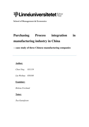
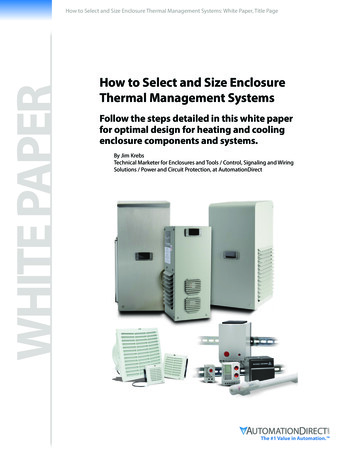
Part E: Analysis of Thermal Failure of Electronic Components25. Analysis of Thermal Stresses and Strain25.1 IntroductionFor many years the reliability of an electronic system was based, to a great extent, upon thejunction temperatures of the semiconductor devices. Substantial efforts were made in thefabrication methods, mounting methods, and cooling techniques of the electronic devices toreduce these hot spot temperatures below 100 C. This has produced a significantimprovement in the reliability and effective operating life of the equipment. However, theelectronic failure rates are still too high. Additional reductions in the failure rates must beachieved to further improve the reliability of our electronic equipment.Some of the failure mechanisms that can cause malfunctions in electronic systems areexamined in this chapter. Experience has shown that most of these failures are produced by amismatch in the thermal coefficients of expansion (TCE) of the different types of materialstypically used in electronic assemblies. The mismatch often generates high forces andstresses, which produce fractures and cracks in the electronic components and assemblies.An examination of a large number of avionics failures has shown that most of them aremechanical in nature. They typically involve fractures in solder joints, electrical lead wires,plated throughholes (PTH), electrical cables, connectors, adhesive bonded joints, andhermetic seals. These failures are often produced by various combinations of thermal,vibration, shock, humidity, and salt environments, combined with poor manufacturingprocesses and poor design practices. These failures must be reduced in order to achieve asubstantial improvement in the system reliability.25.2 Thermal Expansion Effects in Electronic EquipmentsElectronic assemblies utilize a wide variety of plastics and metals in the fabrication andmanufacturing of their products. These materials can have significant differences in theirthermal TCE, which may result in high strains and stresses in the lead wires, solder joints,and PTH if these factors are not understood or if they are ignored. Temperature changes willproduce dimensional changes in almost all materials normally used in the assembly ofelectronic chassis and PCBs. Dimensional changes can occur due to power cycling where thepower is turned on and off, which induces temperature changes within the electronicassembly. This can also be caused by thermal cycling, where the outside ambient temperaturechanges and the thermal lag within the chassis forces thermal gradients to develop because ofdifferent mass effects. These dimensional changes, which can occur along the X, Y, or Z axesof the electronic assemblies, can produce a wide variety of failures in the structural elementsof these assemblies.Consider a surface mounted transformer on a PCB, as shown in Figure 25.1. Thermalexpansion differences between the component and the PCB along the X and Y axes (in theplane of the PCB) can produce failures in this subassembly after 12 thermal cycles from -55to 95 C. The failures will not be in the lead wires or in the solder joints. Instead, thefailures will occur in the solder pads, which will be lifted off the surface of the PCB byMPE 635: Electronics Cooling2
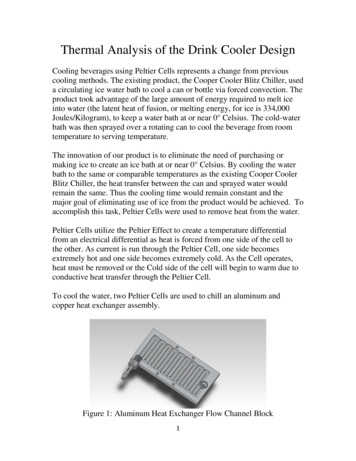
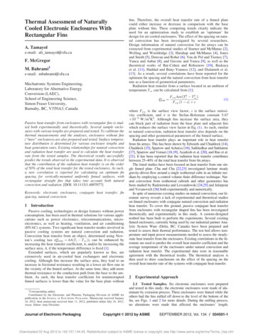
Part E: Analysis of Thermal Failure of Electronic Componentsoverturning moments in the lead wires. These moments are caused by the expansiondifferences between the transformer and the PCB because each material has a different TCE.Figure 25.1 Surface mounted transformer where differences in expansion produce bending inthe lead wiresAlthough epoxy is used in the PCB and for potting the transformer, the PCB contains glassfibers which have a low TCE. This reduces the TCE of the PCB in the X and Y planes, so thePCB expands and shrinks less than the transformer. This expansion difference produces thehigh forces in the lead wires. The wires transfer the load to the solder pads, lifting the pads,which are only cemented to the surface of the PCB.Plated throughholes can be added to anchor the pads to prevent the pads from lifting off thePCB. The fatigue life of the assembly will now be increased to about 150 thermal cycles from-55 to 95 C, where solder joint shear failures can now be expected.Example: Determine the deflections and thermal stresses expected in the lead wires andsolder joints of the surface mounted transformer shown in Figure 25.2, when it is mounted onan aluminum composite PCB which experiences in plane (X and Y) thermal expansionduring rapid temperature cycling tests over a temperature range from -55 to 95 C, with noelectrical operation.Figure 25.2 Dimensions of a surface mounted transformerMPE 635: Electronics Cooling3
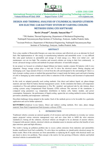
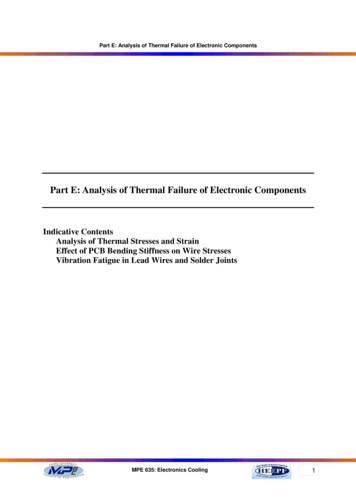
Part E: Analysis of Thermal Failure of Electronic ComponentsSolution:Thermal expansion differences between the transformer and the PCB in the X-Y plane willproduce a force on the lead wires and cause them to bend. This same force will produce ashear stress in the solder joint at the junction of the lead wire and the PCB. Since all massestend to expand with respect to their centroid (or center of mass) and the proper length mustbe used in the expansion calculations. For a symmetrical structure, the effective length issimply half of the total length. Average physical properties must be used for the TCE of thetransformer, which has an epoxy potting outer shell around a copper-iron core. This is alsotrue for the PCB, which has an aluminum heat sink laminated between two epoxy fiberglasscircuit boards, so an average TCE must be used for this subassembly.The temperature is cycled over a range from -55 to 95 C, for a total difference of 150 C inthis sample problem. However, the stresses are determined for a temperature range of only 75 C, which is half of the total temperature range experienced. The 75 C temperature range isused because it represents the stresses that will be developed during cycling from a neutralstress point to the maximum positive stresses, and from a neutral stress point to the maximumnegative stress.In this case the neutral stress point would be at 20 C. Increasing the temperature 75 Cwould bring the temperature to 95 C. Decreasing the temperature 75 C from the neutralpoint of 20 C would bring the temperature down to -55 C.The solution divided into three parts:1) Determine the expansion differences between the transformer and the PCB in X-Y planesisX (aT - aP) b t(25.1)Where:aT average TCE of transformer, considering a mixture of epoxy potting copper, and iron corein and PCB in X-Y plane (Z axis expansion are ignored here) 35 x 10-6 in/in/ C or 35 parts per million/ C (35 ppm/ C)aP average TCE of composite PCB with epoxy fiberglass and aluminum heat sink core inX-Yplanes 20 x 10-6 in/in/ C or 20 parts per million/ C (20 ppm/ C)b 1.2/2 0.6 in (effective length of transformer, including wire length with the transformer) t 95-(-55) 150 C ( peak to peak temperature range ) t 150/2 75 C (neutral point to high and low temperature )Substituting in Equation 25.1 yields toX (35-20) x10-6(0.6) (75) 0.000675 in2) Determine the horizontal force induced in the wire as it is forced to bend through thisdeflection. The wire geometry is shown in the following Figure 25.3.MPE 635: Electronics Cooling4
Part E: Analysis of Thermal Failure of Electronic ComponentsFigure 25.3 Deflection forces the lead wire to bendThe horizontal displacement of a square frame with clamped ends, with bending of both wirelegs due to the action of the lateral force (P), can be determined from the following equationX PL3W7.5 EW I W(25.2)Where:X 0.000675 in (wire displacement in X-Y plane)LW 0.1 in (vertical and horizontal wire length)π d 4 π (0.032) 4IW 0.051x10 -6 in 4 (wire inertia)6464EW 16x106 psi (modulus of elasticity, copper wire)Substituting in Equation 25.2 yields to7.5(0.000675)(16 x10 6 )(0.051x10 6 )P 4.13 Ib(0.1) 33) Determine the bending stress in the lead wire and the shear stress in the solder joint.The bending moment (P) in the wire at the solder joint can be determined from Figure 25.2, bysumming up the bending moments for the wire frame.M 1.2PLW (wire bending moment) 1.2(4.13x0.10) 0.495 lb in(25.3)Then the bending stress (Sb) in the wire can be obtained as in Equation 25.4Sb KMCIWMPE 635: Electronics Cooling(25.4)5
Part E: Analysis of Thermal Failure of Electronic ComponentsWhere:K Stress concentration factor 1 hereC Wire radius to neutral axis 0.032/2 0.016 inSubstituting in Equation 25.4 yields toSb (0.459)(0.016) 155294 Ib/in 2-60.051 x10This far exceeds the ultimate tensile stress of 45,000 psi for the copper lead wire, whichmeans that the wire will be in the plastic bending range. However, testing experience withthis condition shows that the probability of a wire failure is low (if there are no sharp cuts inthe wire) due to the low number of stress cycles normally expected for this type ofenvironment.The direct shear stress (Ss) in the solder joint can be obtained from the solder pad areaestimated to be about 0.09 in x 0.032 in. This direct shear stress does not include solder jointstresses produced by the overturning moment. Both stresses may be combined to obtain themaximum or the Von Mises stress. Only the shear stresses were used here to determine theapproximate fatigue life of the solder joint. Stress concentrations are not considered herebecause the solder is so plastic.P(25.5)Ss AWhere: P 4.13 IbA 0.09 in x 0.032 in 0.00288 in2Then the direct shear stress isSs 4.13 1434 Ib/in 20.0028825.3 Reducing the Thermal Expansion Forces and StressesLower forces and stresses in the electrical lead wires and solder joints will lead to a longerlife with a higher reliability. The Equation 25.2 shows that the forces in the lead wires can bereduced by (a) decreasing the moment of inertia I, (b) decreasing the deflection of the wire X,or (c) increasing the length of the wire L.(a) Decreasing the moment of inertia IThe moment of inertia of the component wire can be reduced by coining (squeezing orrolling) the round wire into a flat thin rectangular cross section. This will decrease the forcein the wire, which will decrease the wire bending stress and the solder joint shear stress.Coining will also increase the width of the lead wire at the solder joint, which will increasethe solder joint area and further reduce the solder joint stress. MIL-STD-2000 solderspecification requires surface mounted components, with axial leads, to have their wirescoined before they are soldered to the circuit boards.MPE 635: Electronics Cooling6
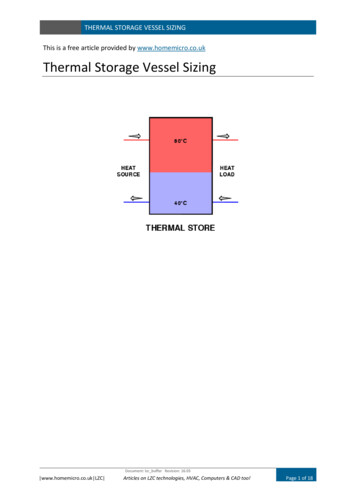
Part E: Analysis of Thermal Failure of Electronic ComponentsCoining may be expensive since special machines are required for this operation. For a largemanufacturing facility, where millions of components are involved, the coining costs for eachcomponent will be relatively small. However, for a small company the cost of the coiningequipment can be too great, so other ways for mounting the components may have to beexamined.In the previous sample problem, if the lead wires are coined to a cross section that measures0.010 in thick and 0.080 in wide (which maintains the same cross-sectional area), the forcesand stresses will be reduced. The reduction will be directly related to the different momentsof inertia for the wire cross sections, as shown in Equation 25.2. The new moment of inertiabecomes.I (0.08)(0.01) 3 6.667 x10 -9 in 412From Equation 25.2 the new shear force isP 7.5(0.000675)(16 x10 6 )(6.667 x10 9 ) 0.54 Ib(0.1) 3Substituting in Equation 25.5.With 0.09 in x 0.08 in estimated area yields to0.54Ss 75 Ib/in 2(0.09)(0.08)This low solder shear stress will provide a good fatigue life.(b) Decreasing the deflection of the wire XWire deflections can be reduced by reducing the relative differences in the TCE between thecomponent body and the PCB. In this application, the transformer has a TCE that is muchgreater than the TCE of the PCB, so the transformer expands and shrinks more than the PCB,producing high forces in the wires. Expansion differences can be reduced by increasing theTCE of the PCB or by reducing the TCE of the transformer, so the mismatch between them isreduced. It is a far easier task to reduce the TCE of the transformer by simply adding calciumcarbonate or aluminum oxide powder to the epoxy solution before encapsulating the transformer. The reduction in the transformer TCE will be related to the amount of material addedto the epoxy solution. An overall reduction in the transformer TCE of about 10% or 3.5ppm/ C can be achieved. This will reduce the difference in the TCE as shown in Equation.25.1. From 35 - 20 15, to 31.5 - 20 11.5 ppm/ C. This ratio is 11.5/15 0.766.This means that the forces and stresses will only be 76.6% of the levels previously shown,when the transformer TCE is reduced by 10%.(c) Increasing the length of the wire LIncreasing the wire length will rapidly reduce the forces developed in the lead wires, becausea cubic function is involved here. The wire length can be increased by using camel humps orloops as shown in Figure 25.4.MPE 635: Electronics Cooling7
Part E: Analysis of Thermal Failure of Electronic ComponentsIf the wire length increased 50% to a length of 0.15 in, the wire force will be reduced to 1.22pounds. This will reduce the bending stress to 68900 psi and solder shear stress to 424 psi.Figure 25.4 Methods for increasing the wire length to decrease the forces and stresses in thesolder joints25.4 X-Y Thermal Expansion Stresses for Throughhole MountingA large number of components such as resistors, capacitors, diodes, flat pac
Analysis of Thermal Stresses and Strain Effect of PCB Bending Stiffness on Wire Stresses Vibration Fatigue in Lead Wires and Solder Joints . Part E: Analysis of Thermal Failure of Electronic Components MPE 635: Electronics Cooling 2 25. Analysis of Thermal Stresses and Strain 25.1 Introduction For many years the reliability of an electronic system was based, to a great extent, upon the .