Transcription
Cisco Unified ICMACD Supplement for AspectContact ServerMay 20142014
THE SPECIFICATIONS AND INFORMATION REGARDING THE PRODUCTS IN THIS MANUAL ARE SUBJECT TO CHANGE WITHOUTNOTICE. ALL STATEMENTS, INFORMATION, AND RECOMMENDATIONS IN THIS MANUAL ARE BELIEVED TO BE ACCURATE BUT AREPRESENTED WITHOUT WARRANTY OF ANY KIND, EXPRESS OR IMPLIED. USERS MUST TAKE FULL RESPONSIBILITY FOR THEIRAPPLICATION OF ANY PRODUCTS.THE SOFTWARE LICENSE AND LIMITED WARRANTY FOR THE ACCOMPANYING PRODUCT ARE SET FORTH IN THE INFORMATIONPACKET THAT SHIPPED WITH THE PRODUCT AND ARE INCORPORATED HEREIN BY THIS REFERENCE. IF YOU ARE UNABLE TOLOCATE THE SOFTWARE LICENSE OR LIMITED WARRANTY, CONTACT YOUR CISCO REPRESENTATIVE FOR A COPY.The Cisco implementation of TCP header compression is an adaptation of a program developed by the University of California, Berkeley (UCB)as part of UCBs public domain version of the UNIX operating system. All rights reserved. Copyright 1981, Regents of the University of California.NOTWITHSTANDING ANY OTHER WARRANTY HEREIN, ALL DOCUMENT FILES AND SOFTWARE OF THESE SUPPLIERS AREPROVIDED "AS IS" WITH ALL FAULTS. CISCO AND THE ABOVE-NAMED SUPPLIERS DISCLAIM ALL WARRANTIES, EXPRESSED ORIMPLIED, INCLUDING, WITHOUT LIMITATION, THOSE OF MERCHANTABILITY, FITNESS FOR A PARTICULAR PURPOSE ANDNONINFRINGEMENT OR ARISING FROM A COURSE OF DEALING, USAGE, OR TRADE PRACTICE.IN NO EVENT SHALL CISCO OR ITS SUPPLIERS BE LIABLE FOR ANY INDIRECT, SPECIAL, CONSEQUENTIAL, OR INCIDENTALDAMAGES, INCLUDING, WITHOUT LIMITATION, LOST PROFITS OR LOSS OR DAMAGE TO DATA ARISING OUT OF THE USE ORINABILITY TO USE THIS MANUAL, EVEN IF CISCO OR ITS SUPPLIERS HAVE BEEN ADVISED OF THE POSSIBILITY OF SUCHDAMAGES.Any Internet Protocol (IP) addresses used in this document are not intended to be actual addresses. Any examples, command display output,and figures included in the document are shown for illustrative purposes only. Any use of actual IP addresses in illustrative content isunintentional and coincidental.Cisco and the Cisco logo are trademarks or registered trademarks of Cisco and/or its affiliates in the U.S. and other countries. To view a list ofCisco trademarks, go to http://www.cisco.com/go/trademarksThird-party trademarks mentioned are the property of their respective owners. The use of the word partner does not imply a partnershiprelationship between Cisco and any other company. (1110R)Copyright 2014 Cisco Systems, Inc. All rights reserved.
PrefaceContentsPreface. viiPurpose . viiAudience . viiOrganization . viiTypographic Conventions . viiOther Publications . viiiObtaining Documentation, Obtaining Support, and Security GuidelinesviiiDocumentation Feedback . viii1. Overview . 91.1. ACD Interface Requirements . 101.1.1. General Network Requirements . 101.1.2. Network Addresses . 101.1.3. Application Bridge . 111.1.4. Real-Time Bridge . 111.1.5. Optional Application Bridge Server . 111.1.6. Multiple ACDs . 121.1.7. Multiple PGs . 121.1.8. Remote PG Configuration . 121.2. Hardware and Software Requirements . 131.2.1. Supported Unified ICM Features . 141.2.2. Multiple Application Support . 141.2.3. ACD Restrictions . 142. ACD Configuration . 152.1. Data Link Configuration . 162.1.1. Aspect Administrator . 162.1.2. Web Setup Tool . 192.2. Application Bridge Configuration . 20iii
iv2.3. Real-Time Bridge Configuration . 202.3.1. Real-Time Bridge Data Timeout Configuration . 202.4. Unified ICM-Required CCT Programming . 202.4.1. Call Event Notifications . 212.5. Changes to Support Post-Routing . 242.5.1. Route Call Request Message (CIM) . 242.5.2. Transfer Call Request Message (CIM) . 242.5.3. Adjunct Route Request Message (ARR) . 242.5.4. Example CCT for Two-Step RC Dialog. 252.5.5. Example CCT for Three-Step RC Dialog . 262.6. Maintaining Your Configuration . 272.7. Aspect Contact Server Integration . 272.7.1. Installing the Aspect Contact Server CMI Server . 282.7.2. Installing the Aspect CMI Server Sample Application . 282.7.3. CMI Server Data Link Configuration . 292.7.4. Aspect CMI Server Configuration . 292.7.5. Testing Connectivity with the CMI Server . 353. Unified ICM Configuration . 373.1. Peripheral Configuration . 383.1.1. Peripheral Configuration Parameters. 383.1.2. Peripheral Call Control Variable Map. 393.2. Peripheral Target Configuration . 423.3. Trunk Group Configuration . 433.4. Trunk Configuration . 433.5. Service Configuration . 433.6. Skill Group Configuration . 433.7. Skill Group-to-Service Mapping . 443.8. Agent Configuration . 443.9. Agent States . 443.10. Route Configuration . 453.11. Translation Route Configuration . 463.12. Routing Client Configuration . 463.13. Application Bridge Server . 463.13.1. ABS Client . 46iv
v3.14. Maintaining Your Configuration . 494. Post-Routing . 514.1. Routing Client Dialogs . 524.1.1. Route Request (Two-Step RC) . 524.1.2. Adjunct Route Request (Three-Step RC) . 524.1.3. Adjunct Route End/Timeout . 534.1.4. Route Select . 534.2. Label Syntax. 544.2.1. Label Examples. 554.2.2. Network Take-Back and Transfer Support . 555. Redundant CMI Support . 585.1. Overview of Dual CMI Configuration . 595.1.1. Interface Specifications . 59Appendix A: Outstanding Event Link Issues . 1Index . 1vv
vivi
viiPrefacePurposeThis document discusses maintenance of an Aspect Peripheral Gateway(PG) in a Cisco Unified Intelligent Contact Management (Unified ICM)environment. Use this document as the Aspect-specific companion to theCisco Unified ICM documentation set.The ACD Supplement for Aspect provides specific information onconfiguring an Aspect PG.AudienceThis document is for system managers. The reader must understandUnified ICM installation, configuration, and scripting. The reader alsorequires a specific knowledge of the Aspect Call Center ACD.OrganizationChapter 1, “Overview”Provides an overview of ACD interface and hardware and softwarerequirements.Chapter 2, “ACD Configuration”Describes items in the Aspect configuration that must be checked toensure compatibility with Unified ICM.Chapter 3, “Unified ICM Configuration”Describes the relationships between the Aspect ACD objects andUnified ICM database objects. This chapter also describes Aspectspecific settings to confirm in Unified ICM configuration.Chapter 4, “Post-Routing”Describes the features of Unified ICM Post-Routing available with theAspect PG.Chapter 5, “Redundant CMI Support for Aspect Contact Server”Describes the redundant CMI Server support by the Aspect ContactServer PG.Appendix A, “Outstanding Event Link Issues”Highlights several outstanding issues with the Aspect Event Link inCall Center Release 6.0.Typographic ConventionsThis manual uses the following conventions: Boldface type is used for emphasis; for example:Real-time information is not stored in the central database.viivii
viii Italic type indicates one of the following: A newly introduced term; for example:A skill group is a collection of agents who share similar skills. A generic syntax item that you must replace with a specific value;for example:IF (condition, true-value, false-value) A title of a publication; for example:For more information, see Database Schema Guide for CiscoUnified ICM/Contact Center Enterprise & Hosted.Sans serif type with small caps is used to represent keys on yourkeyboard; for example:Press the SHIFT key to select a range of items.An arrow ( ) indicates an item from a pull-down menu. For example,the Save command from the File menu is referenced as File Save.Other PublicationsFor more information on Unified ICM, see the following documents: Administration Guide for Cisco Unified Contact Center Enterprise &Hosted Cisco Unified Contact Center Enterprise Installation and UpgradeGuide Configuration Guide for Cisco Unified ICM/Contact CenterEnterprise & Hosted Scripting and Media Routing Guide for Cisco Unified ICM/ContactCenter Enterprise & HostedFor information on Cisco Network Applications Manager (NAM), see thefollowing documents: Product Description Guide for Cisco Unified ICM HostedSetup and Configuration Guide for Cisco Unified ICM Hosted EditionObtaining Documentation, Obtaining Support, and SecurityGuidelinesFor information on documentation, technical support, and securityguidelines, see the monthly What's New in Cisco Product Documentation.This guide lists all new and revised Cisco technical ral/whatsnew/whatsnew.htmlDocumentation FeedbackTo provide comments about this document, send an email message to thefollowing address: contactcenterproducts docfeedback@cisco.com.We appreciate your comments.Hviii
91. OverviewUnified ICM Peripheral Gateway interacts with two Aspect softwarepackages on the Aspect Call Center ACD: the Application Bridge EventLink Interface and the Real-Time Bridge. The PG uses the ApplicationBridge Event Link interface to monitor agent status and call states. TheEvent Link interface consists of a set of unsolicited messages that indicatetransitions in agent and call state.The Peripheral Gateway uses the Aspect Real-Time Bridge to access realtime agent group, trunk group, and application statistics. The PG requiresthis data from the Aspect ACD for use in call routing and real-timereporting.This chapter describes the options for connecting the Aspect Call CenterACD to the Cisco Unified ICM PG. This chapter also lists the hardwareand software required for the Aspect Call Center to work with UnifiedICM.
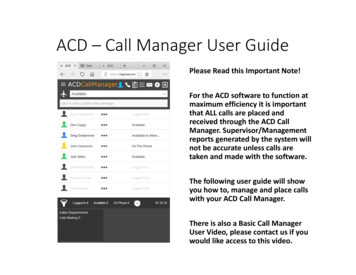
10Overview1.1. ACD Interface RequirementsA basic, simplex Aspect PG has the following interface requirements: One Real-Time Bridge Client. If more than one application uses the Application Bridge, the CiscoApplication Bridge Server software is required.Application Bridge Software (TCP/IP version).An extra Application Bridge Data Link required for redundant PGinstallations.1.1.1. General Network RequirementsThe Aspect ACD connects to the Peripheral Gateway (PG) through asingle Ethernet thin-net cable. The termination points for the thin-net cablecan be a HUB port on Unified ICM visible LAN or directly to the AspectPG (50-ohm terminator required). The exact network requirements dependon the customer's needs for access to other applications on the Aspect CallCenter. The PG connects to Unified ICM visible LAN through an Ethernetcable. Figure 1 shows the Aspect Call Center-PG interface in a redundantPG environment.Figure 1: Aspect PG Interface (Redundant PGs)1.1.2. Network AddressesOn the Aspect ACD, configure both Off-Board Processor (OBP) andApplication Bridge (AB) TCP/IP network addresses for the PG. Theseaddresses provide the PG with access to the Real-Time Bridge andApplication Bridge, respectively.The redundant PG configuration for the Aspect ACD, as shown in Figure1, requires another PG, another Ethernet connection to the visible LAN,10
ACD Interface11 Requirements11and another set of addresses (OBP and AB) on the ACD. In redundant PGconfigurations, both PGs must use the same OBP and AB networkaddresses on the ACD. Only one side of the redundant PG pair can have anactive Application Bridge and Real-Time Bridge connection.1.1.3. Application BridgeThe PG monitors agent and call activity on the Aspect ACD through theApplication Bridge Event Link Interfaces. This connection also supportsUnified ICM Post-Routing capabilities.Note: Unified ICM supports only the TCP/IP version of the ApplicationBridge.The Application Bridge Event Link Interface is an Aspect softwarepackage. The Event Link provides a set of unsolicited messages fromthe Application Bridge that indicate changes in agent “can call” state.The Application Bridge must be installed and enabled in order forUnified ICM to run. The Aspect Application Bridge Interface and the Contact Server(CMI) Interface does not support device status query. So, callsurvivability does not exist at Unified ICM during PIM failures.1.1.4. Real-Time BridgeUnified ICM requires that you install and enable the Real-Time Bridgesoftware option. The Aspect Real-Time Bridge is an Aspect softwarepackage that provides access to miscellaneous aggregated data on theAspect ACD about calls and agents. The PG retrieves data from the RealTime Bridge through Aspect-proprietary, SQL-like queries. The PGreceives responses to its queries every three seconds. That rate is theminimum refresh rate supported by Aspect. The data retrieved through theReal-Time Bridge supports Unified ICM call routing and real-timereporting.1.1.5. Optional Application Bridge ServerThe Aspect Application Bridge provides a Call Disconnect Message(CDM) or Call Transfer Message (CTM) only to the last ApplicationBridge data link that handled the call. This behavior can cause othermonitoring applications to miss a CDM or CTM. The loss of a CDM orCTM can leave call states hanging until certain recovery checks areenabled.To avoid the loss of CDM and CTM messages, Cisco provides theApplication Bridge Server (ABS) option. The Cisco Application BridgeServer ensures that all applications that track a call receive a CDM orCTM for disconnected or transferred calls.For example, assume that one data link informs an application of a call.The Aspect Call Center ACD performs a Unified ICM post-route requestto the PG over another data link. Without the ABS, the monitoringapplication misses the Call Transfer Message or Call Disconnect Message.11
12OverviewNote: Cisco PGs that use the Application Bridge Event Link interface rely onevent messages from the Application Bridge. They do not use CallDisconnect and Call Transfer messages. In most cases, these PGs do notrequire the ABS option.Consult with your Cisco Unified ICM project manager to determine ifyour specific Unified ICM application requires the ABS software.See also: For more information on the Application Bridge Server software, seeChapter 3, “Unified ICM Configuration.”1.1.6. Multiple ACDsA simplex or redundant PG can connect to up to five Aspect ACDssimultaneously. Before connecting multiple ACDs to a single PG, ensurethat the data link between the PG and Unified ICM Central Controller hasthe necessary bandwidth. To handle multiple ACDs, you might require ahigh-end PG platform with more processing capability and memory.1.1.7. Multiple PGsThe Aspect ACD (and Contact Server) allows connection from multiplePGs. However, in that configuration, maintain the resources (like Agents,Applications, CCTs, dial plans, Trunk, and Trunk Groups) that each PGuses as separate configurations.Even when you follow these configuration guidelines, there are someknown limitations and risks in using such systems: Aspect sends all the call and agent events for a PG to all the other PGsas well. Problems related to reporting of calls for other PGs can exist. When such configurations are servicing two different customers, thecall statistics and agent statistics can be shared across customers.Note: Contact the ACD vendor for ACD-related issues or limitations onconnecting multiple PGs to a single ACD.1.1.8. Remote PG ConfigurationThe Aspect Event Link PG supports a remote TCP/IP connection to theACD as long as enough network bandwidth is provided. For ACDs thatimplement Post-Routing, a three-second response time is required.12
Hardware and Software13 Requirements131.2. Hardware and Software RequirementsIn order to work with Unified ICM, configure the Aspect Call Center ACDwith the hardware and software listed in Table 1.Table 1: Aspect Call Center System RequirementsReleases SupportedFor specific release information for Aspect, see theCisco Unified ICM Supported Switches (ACDs)document. This document can be found onwww.cisco.com.Unified ICM 8.x requires Aspect v9.2 and CMI v5.2minimum.Unified ICM 9.x does not support Aspect.Unified ICM 10.0 requires Aspect v9.3 and CMIv6.4.Features RequiredOne Real-Time Bridge client for the PG.Application Bridge software (TCP/IP version) withthe Event Link interface option.An extra Application Bridge data link in a redundantPG configuration.Event monitoring must be enabled on theApplication Bridge.OptionalYou might require Application Bridge Serversoftware if a Call Center CTI application affectsUnified ICM monitoring of call events. (See“Optional Application Bridge Server” for moreinformation.)PerformanceReal-Time Bridge minimum refresh rate: 3 seconds.ACD ProcessorRequirements68040, 33 MHz or faster, 32-MB RAMAdministrative ProcessorAdministrative Processor must be an MVE167 classprocessor card.11The faster class processor board is required because of the additional loadUnified ICM places on the Aspect Call Center ACD.13
14Overview1.2.1. Supported Unified ICM FeaturesThe Aspect Call Center ACD supports the following Unified ICMfeatures: Pre-RoutingPost-RoutingEnterprise CTI (includes third-party call control)1Agent reportingRedundant PG implementationUnified ICM Web OptionRedundant CMI Server implementation21.2.2. Multiple Application SupportMultiple applications applying treatment to a call can require Unified ICMApplication Bridge Server to distribute the Call Disconnect and CallTransfer Messages (CDM/CTM). The Application Bridge Server allowsmultiple applications to share the Aspect Application Bridge.See also: For more information, see “Optional Application Bridge Server,” earlier inthis chapter.1.2.3. ACD RestrictionsThe Aspect ACD limits agents to one skill group assignment per agent.141For third-party call control, the Aspect Call Center ACD must be running theApplication Bridge Event Link interface.2The Redundant CMI Server support is available from ICM 7.0 SR1 onwards
152. ACD ConfigurationProper operation with Unified ICM requires some configuration setting changeson the Aspect Call Center ACD. For example, modify the Aspect Call Center CallControl Tables (CCTs) to include SEND DATA steps to notify Unified ICM ofcall state transitions. You must also set certain elements properly in the AspectData Interlink Configuration Table.This chapter describes these settings. It also provides guidelines to maintain yourAspect and Unified ICM configurations.
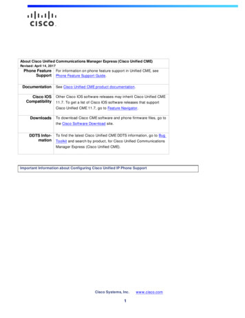
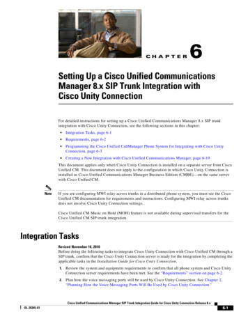
16ACD Configuration2.1. Data Link Configuration2.1.1. Aspect AdministratorFigure 2 shows the settings required for Unified ICM in the Aspect Data InterlinkConfiguration Table. This table can be displayed by choosing DataBase Resources DataInterlink Update at the Aspect Call Center Workstation.Note: The current configuration requires that you do not use the redundant link option.Using this option invalidates the data received by the PGs. This redundant linkoption could change in the future given the Aspect or PG code updates.Data InterLink Number 12Description: CISCOPG1AVersion Number 4 Release 6.0Backup Link Physical Protocol 2Port: 6101Link Protocol 3CallCenter Address: CallCenterData Sys Address Ciscopg1aMessage Format VField Separator 10Send Type YDisconnect Notices NSubtype:Transfer Notices NSubtype:Character Set AReceive Data Timeout: 6Monitor Host Y Interval: 10Port - Port number configured for the data link that corresponds to the PortNumberconfigured during setup installation of the PG software.FieldSeparator - Defines the character used to separate fields within the ApplicationBridge Message. Value specified must match the FieldSeparator elementconfigured during setup installation of the PG software.ReceiveDataTimeout - 3 or greater if network requires and should match theconfigured Routing Client timeout value.Figure 2: Aspect Data Interlink Configuration TableAspect includes an integrated set of applications. These applications, the AspectSystem Management Suite, provide a GUI to directly access all the Aspect systemresources and features. Once installed, you can access the HardwareAdministrator, Agent Administrator, Route Administrator, System Administrator,Aspect Alert Manager, and the Aspect Architect Program.16
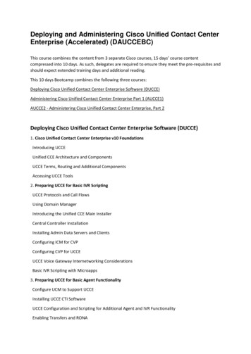
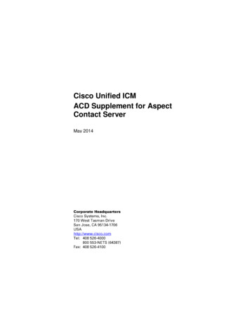
Data Link Configuration1717The new Data Link Configuration Utility (accessed through the HardwareAdministrator) is shown in Figure 3.Figure 3: Data Link Configuration UtilityThe Properties Page for the selected Interlink contains several tabs. The Generaltab is shown in Figure 4.Figure 4: General TabThe “Backup Link” parameter MUST be set to “None (0)”. This settingeliminates duplicate messaging and link alarms. Link alarms are generated whenthe PIM for the “backup” link is the active side. (The Application has logic to trythe primary link before the backup. When the primary link fails, a warning isgenerated even though the call is handled correctly).WARNING: Use of the “Backup Link” parameter causes an unacceptable PIMbehavior. DO NOT configure a link for the “Backup Link”.17
18ACD ConfigurationThe Settings tab is shown in Figure 5.Figure 5: Settings TabThe Message Format tab is shown in Figure 6.Figure 6: Message Format TabOn the Message Format tab of the Aspect device interlink window, do not checkeither Send a Disconnect Notice or Send a Transfer Notice. If checked,duplicate messages are sent to the Event.Set the field separator to a comma (not a slash). The comma is the only messagefield separator that the Aspect CMI Server recognizes. If you configure thissetting incorrectly, the CMI Server does not forward messages from the ACD tothe PIM.18
Data Link Configuration1919The Monitoring and Timeout tab is shown in Figure 7.Figure 7: Monitoring and Timeout Tab2.1.2. Web Setup ToolThe “backup” configuration parameters on the Aspect Event LinkConfiguration dialog in WEB SETUP TOOL are no longer supported.Configure the Side A and Side B PIM without these “backup” parameters. Ensurethat each PG has just one unique data link associated with it. For example,assume that the Aspect Hardware Administrator configured data link #12 for theSide A PG (host name “AspectPG1A”) and data link #13 for the Side B PG (hostname “AspectPG1B”). You see the following PIM:19
20ACD ConfigurationFigure 8: PIM Configuration for Side A and Side BAs shown in Figure 8, “callcenter” is the ACD host name. The Datalink Port isthe port that was configured through the Aspect Hardware Administrator for theassociated data link ID. Leave AB backup call center and Backup EMR link IDblank.2.2. Application Bridge ConfigurationTypically, an Aspect Field Engineer performs the configuration setup for theApplication Bridge connection to the PG.2.3. Real-Time Bridge ConfigurationBefore you can configure the Real-Time Bridge access to the Aspect Call Center,an Aspect Field Engineer must configure an Off-Board Processor Workstation.2.3.1. Real-Time Bridge Data Timeout ConfigurationThere is a timeout value in the registry in the following PIMS\ProcessName\AspPIMData\DynamicThe key has the following entries: SwitchDataWaitTimeout. Real-Time Bridge default timeout value fordetermining if the socket connection from the PIM to the Real-Time Bridge isunable to process data messages. The PIM checks during switch events if theswitch data is not received for the timeout period. If the PIM receives no datamessages during this period, the socket connection aborts and restarts. If thisfailure occurs a second time, the PIM restarts if theRestartPIMOnSecondRTBFailure is set to true (1) in the registry. The defaultvalue for this parameter is 30 seconds. RestartPIMOnSecondRTBFailure. Real-Time Bridge value (Boolean) usedto determine if the PIM restarts on a second consecutive failure to read fromthe Real-Time Bridge. Use this option to prevent the socket connection to theReal-Time Bridge from hanging during a read attempt. The default value iszero (0). With the default value, the PIM does not restart on a secondconsecutive failure.2.4. Unified ICM-Required CCT ProgrammingThe following sections describe the modifications to the Call Center CCTs toenable the Aspect Call Center to function with Unified ICM.Note: Aspect Call Center provides support for a Redundant Data Link configuration.When implementing CCT modifications for a redundant PG, keep the followingpoints in mind:20
Unified ICM-Required CCT Programming2121 The CCT targets only a single Data Link. The Call Center targets the message to and from the Backup Data Link if thePrimary Data Link is OFFLINE and the Backup Data Link is ONLINE.The Call Center targets the message to and from the Primary Data Link if it isONLINE.This setup enables redundant PG configurations to only invoke a single CCT stepto target MESSAGES to and from the Primary and Backup PGs.2.4.1. Call Event NotificationsThe Aspect Event Link interface informs a monitoring application of transitionsin Agent and Call states for actively monitored Trunk Groups and Agent Groups.The monitoring application enables Event Notifications for the required TrunkGroups and Agent Groups.The following sections define cases where you need enhancements to CCTs toproperly track the transition in Call States. These steps are required to track callsin Unified ICM where call transitions are missing on the Aspect Event LinkInterface.The Aspect PG decodes the Application Bridge Call Information Message subtype to determine a call state change.Note: The Aspect Call Center’s Application Bridge Link provides a Call DisconnectMessage and a Call Transfer Message implicitly over the last Data Link thatprovide call treatment on the disconnected or transferred call.Call Offered Public (COP)Unified ICM requires that transition in call targets be noticed when they occur.Transition in call targets is a CALL CONTROL TABLE CCT step to a CCT thatis associated with a different Call C
Center. The PG connects to Unified ICM visible LAN through an Ethernet cable. Figure 1 shows the Aspect Call Center-PG interface in a redundant PG environment. Figure 1: Aspect PG Interface (Redundant PGs) 1.1.2. Network Addresses On the Aspect ACD, configure both Off-Board Processor (OBP) and