Transcription
BONDEK DESIGNSOFTWAREUSER GUIDEFOR DESIGN PROFESSIONALS
Welcome to the LYSAGHT BONDEK Design Software User Guide.Our design software will significantly assist a qualified engineerarrive at a solution which speeds the design process for floors andslabs.BONDEK works as composite slab saving on concrete andreinforcement costs.CONDITIONS OF USEThis publication contains technical information on the followinggrades of LYSAGHT BONDEK : LYSAGHT BONDEK 0.6mm thickness LYSAGHT BONDEK 0.75mm thicknessDownload your free copy of the software dek LYSAGHT BONDEK 0.9mm thicknessBACKGROUNDAdditionally, LYSAGHT BONDEK Design Software allows you toget quicker and more economical solutions with a range of options.Call Steel Direct on 1800 641 417 to obtain additional copies ofthe Design and Construction Manual and User Guide to BONDEK Design Software.Our newest release of supporting software and the Design andConstruction Manual for BONDEK Structural Steel Deckingincorporates Lysaght’s latest research and development work.Improved design and testing methods have again pushedBONDEK Structural Steel Decking to the forefront. New formworktables are optimised for steel frame construction but are alsosuitable for concrete frame construction and masonry walls.This User Manual is designed to provide you with basic familiarityabout LYSAGHT BONDEK Design Software to enable youto quickly understand and start using this powerful tool. Thesoftware is able to perform major tasks normally performed at astructural consultant’s office. Use LYSAGHT BONDEK Design andConstruction Manual with its set of tables for typical designs. Thesoftware will help when input parameters are different from thoselisted for tables or the user wants to check several different options.LYSAGHT BONDEK is a profiled zinc-coated high tensile steeldecking for use in the construction of composite floor slabs. It hasbeen successfully used in countless buildings throughout Australia.The profile has been specifically developed for Australian hightensile steels.It can be used as formwork during construction and as areinforcement system in composite slabs. LYSAGHT BONDEK 1.00mm thicknessWhere we recommend use of third party materials, ensure youcheck the manufacturer’s requirements. Diagrams are usedto explain the requirements of a particular product. Adjacentconstruction elements of the building that would normallybe required in that particular situation are not always shown.Accordingly aspects of a diagram not shown should not beinterpreted as meaning these construction or design details are notrequired. You should check the relevant Codes associated with theconstruction or design.WARRANTIESOur products are engineered to perform according to ourspecifications only if they are installed according to therecommendations in this manual and our publications. Naturally, if apublished warranty is offered for the product, the warranty requiresspecifiers and installers to exercise due care in how the productsare applied and installed and are subject to final use and properinstallation. Owners need to maintain the finished work.PREFACEOur increased understanding of composite slabs, together withtesting in our NATA-accredited laboratory and leading Australianuniversities, has paid off with an optimised product, which providessignificant cost savings for projects.LYSAGHT BONDEK Design Software is a user-friendly MicrosoftExcel -based software for the design of composite concrete slabswith LYSAGHT BONDEK structural decking. It is suitable for steelframe construction and masonry supports.The built-in properties of high tensile steel are maximised in thedesign and fabrication of the deck profiles which result in productswith high strength-to-weight ratio. LYSAGHT BONDEK is currentlyone of the most popular structural steel decking profiles in Australiafor typical applications.It is a tool developed with latest information to assist a competentengineer with the most competent solution.SCOPEwww.lysaght.comThis manual provides information on the design of formwork,propping, composite slabs and design for fire and someinformation for composite beams.LYSAGHT BONDEK Design Software is developed to AustralianStandards (AS) whenever possible, Eurocodes have been usedwhen certain design procedures are not available in AustralianStandards.The software should be used to design composite slabs inconjunction with the LYSAGHT BONDEK Design & ConstructionManual.BONDEK DESIGN SOFTWARE2
Contents1.0Introduction42.0Getting started42.1Computer requirementsInstalling LYSAGHT BONDEK Design Software4Software flowchart for the designof continuous spans54.0LYSAGHT BONDEK Design Software menu65.0Input dialogue box75.1General75.2Conditions of exposure75.3Spans75.4Composite slab deflection limits95.5Crack control for flexure95.6Degree of control of shrinkage andtemperature effects95.7Properties of materials105.8Cover to negative bar115.9Fire Design115.10Shrinkage reinforcement115.11Loading parameters126.0Design dialogue box136.1General136.2Slab span136.3Formwork deflection limits136.4Support width146.5Live load146.6Fire design147.0Design/Check dialogue box157.1General157.2Slab thickness158.0Results window168.1General169.0Warning messages1910.0Sample report2111.0Software27 32.23.0BONDEK DESIGN SOFTWARE4
BONDEK DESIGN SOFTWARE1.0 IntroductionThe software offers following additional design options ascompared to tables: Degree of control for shrinkage and temperature effects. T wo major design options: Design and Design/Check. Thefirst option will perform design with the minimum possible slabthickness; the second one will check the chosen slab thicknessand design the rest of the parameters. V ariable loads due to weight of stacked materials duringconstruction stage. Selection of exposure classifications (A1, A2, B1 and B2). Support width. 25, 32 and 40 MPa concrete grades. User specified concrete cover. Superimposed dead load (Gsdl) other than 1 kPa.The software is developed as a powerful tool to minimise timeand calculations by a consulting engineer to complete the job.However, it is essential for the user to have: Other than office types of imposed loads. F or negative, positive fire and shrinkage reinforcement,use D500N or D500L. User specified bar diameter. S pecified number of continuous spans (two-span,three-span etc.). All fire rating periods: 30, 60, 90, 120, 180 and 240 min. Design with relaxed crack control requirements for flexure. Good knowledge of structural engineering. Familiarity with design of composite concrete slabs. Sound knowledge of local regulations and load requirements.!This warning symbol means the user shalltake care before proceeding further.This symbol means that the user shall referto the relevant Australian Standard orEurocode for more information.HELPThis symbol means that there is moreinformation on this topic in other chapters.This symbol means that this is importantinformation. The user shall ensure theyunderstand before proceeding.2.0 Getting Started2.1. COMPUTER REQUIREMENTSTo run LYSAGHT BONDEK Design Software yourcomputer must have Microsoft Excel 2000 or a laterversion, on Windows platform.2.2 INSTALLING LYSAGHT BONDEK DESIGN SOFTWAREThe LYSAGHT BONDEK Design Software can bedownloaded from: e on-line file folder also contains the LYSAGHTBONDEK User Guide and Design and ConstructionManual in .pdf format.BONDEK DESIGN SOFTWAREOn your hard disc, create a directory (folder) calledLYSAGHT BONDEK Design Software, and place thedownloaded files from http://professionals.lysaght.com/products/bondek into the folder. Run thesoftware, in the usual way, by double-clicking on theicons.Ensure you enable Macros before proceeding withLYSAGHT BONDEK Design Software. The securitysettings for Microsoft Excel shall be set to medium tolow level when applicable.4
3.0 S oftware Flowchart for the Design of Continuous SpansRevise input parametersNOSlab thickness known?YESSpecify parametersin Design dialogue boxand click DesignSpecify parametersin Design/Checkdialogue box and clickDesign/CheckThe design output issatisfactory (passed)and economical?The design output issatisfactory (passed)and economical?NOYESLess than five spansYESNORepeat above procedurefor one Interior Span withthicknesses required forEnd Span usingDesign/Checkdialogue box.ENDRepeat above procedure forInterior Spans using eitherof these two options– the same thickness as for End Span,using Design/Check dialogue box– minimum thickness usingDesign dialogue boxRepeat above procedurefor one Interior Span(Equal Spans)or several Interior Spans.ENDENDBONDEK DESIGN SOFTWAREYES5NORevise input parametersSpecify parameters inInput dialogue boxfor End Span
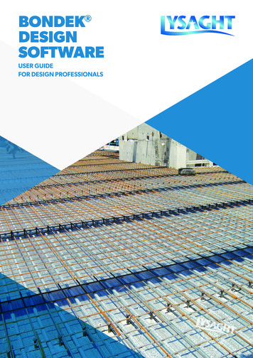
4.0 LYSAGHT BONDEK Software MenuLYSAGHT BONDEK Design Software Menuoptions are built into Excel Menu on the topof the screen.Figure 1Analyse Menu.Excel Menu may look different from what isshown below.There are three additional Menu options: Analyse Print ReportHELPAnalyse Menu has three submenu options:Figure 2 InputPrint Menu. DesignFigure 2 Design/CheckPrint MenuThese options will be described in details infurther chapters.When the software is opened, the Inputdialogue box will appear on the screenautomatically (see cover page). For the secondand consecutive runs, the user shall access theInput dialogue box through Menu.Print Menu allows the user to print Output/Input information or Report.HELPBONDEK DESIGN SOFTWAREReport Menu will generate detailed a designreport which is described in more detail inChapter 10.Figure 3aIt shall be noted that Menu options areavailable only when LYSAGHT BONDEK Design Software Excel file is activated.Figure 3b* For Microsoft Excel 2007 or later versions,the extra functional tabs described above canbe accessed at the Add-ins ribbon.Report Menu.Analyse Menu. Excel 2007 onwards.6
5.0 Input dialogue box5.1 GENERALInput dialogue box is designed for quickand easy data entry. The user shall normallyjust choose one of the available options.If required input information is missed orincorrect, the warning message would appearon the screen.5.2 CONDITIONS OFEXPOSUREFigure 4Exposure classification.The Exposure Classification shall bespecified as required by AS 3600:2009Clause 4.35.3 SPANSFigure 5The user may specify Single Spans orContinuous Spans depending on theproject.Spans.Increased slab thickness may be required inmany instances when continuous slabs aredesigned as a series of simply supportedspans.Figure 6BONDEK DESIGN SOFTWAREContinuous Spans.7If the span is a Continuous one, the usermay run the software several times: for EndSpans and Interior Spans separately. If thecontinuous span is a Two spans then there isno option for Interior Spans, both spans areend ones. It shall be noted that ContinuousSpans refer here to composite concrete slabsonly, LYSAGHT BONDEK formwork spansare specified in Design and Design/Checkdialogue boxes.
!End Spans and Interior Spans may bedesigned with a different thickness to get the mosteconomical design. However, the first InteriorSpan from the end support shall always have thesame thickness as the End Span.When the slab has less than five spans theuser shall run End Spans first using DesignMenu option to get the minimum possible slabthickness.Then Interior Spans shall be designed with theslab thickness obtained for End Spans usingDesign/Check Menu option.When the slab has five or more spans, thethickness of Interior Spans other than first InteriorSpan may be specified independently from EndSpans.Figure 7Spans.End and Interior Spansare the same thicknessLYSAGHT BONDEK End span negativereinforcementInterior span negativereinforcementEnd SpanInterior SpanFigure 8Spans.See flowchart.Slab thickness ofInterior Spansmay be reducedInterior span reinforcementMax as required for adjacent spansLYSAGHT BONDEK End Span!The user may specify all spans as equal spansand with maximum Ratio of longer to shorteradjacent span of 1.2.For software options for irregular lay outs withhigher ratios of adjacent spans, contact SteelDirect or your local technical sales representativefor more information.Figure 9Ratio of Spans.First Interior SpanInterior SpanBONDEK DESIGN SOFTWARE8
5.4 COMPOSITE SLABDEFLECTION LIMITSFigure 10Composite slab deflection limits.The software is developed for Span/250Composite slab deflection limits due to totalload and two options for deflections limits due toimposed loads: S pan/500 is recommended by AS 3600:2009Table 2.3.2 for concrete slabs which supportbrittle partitions like masonry walls, glass doors. No limits for slabs not supporting brittlepartitions5.5 CRACK CONTROL FORFLEXUREFigure 11Crack control for flexure.Not required option may be used for areasof slabs fully enclosed within a building exceptfor a brief period of weather exposure duringconstruction and where it is assessed that widercracks can be tolerated - according toAS 3600:2009 Clause 9.4.1. This option willdesign reinforcement as required for relaxed crackcontrol. Items (a) and (b) of Clause 9.4.15.6 DEGREE OF CONTROLOF SHRINKAGE ANDTEMPERATURE EFFECTSFigure 12Shrinkage control.Refer to AS 3600:2009 Clause 9.4.3 for shrinkagecontrol requirements.Figure 139BONDEK DESIGN SOFTWAREEnvironment for shrinkage strains.
It shall be noted that arid (interior)environment will result in higher shrinkagestrains, which in turn may result in deeperslabs.Figure 14Concrete grades.5.7 PROPERTIES OFMATERIALSThe minimum Concrete grade possibledepends on Exposure Classification.B2 classification will require minimumconcrete grade of 40 MPa.Figure 15Negative bar sizes. Positive and fire bar sizes.Figure 16LYSAGHT BONDEK BMT (base material thickness).BONDEK DESIGN SOFTWARE10
!The software may design composite slabs using:0.6, 0.75, 0.9 or 1.0 BMT sheets. The user maytry 0.6 BMT for the first run. If the design is noteconomical (props are necessary), next run withincreased BMT may be necessary.5.8 COVER TO NEGATIVE BARFigure 17Users shall specify appropriate covers to ensurethat the concrete can be satisfactorily placed andcompacted around reinforcement in accordancewith the requirements of AS 3600:2009, Clause17.1.3 and 4.10.Cover to negative bar.HELP5.9 FIRE DESIGNFigure 18At this stage the user shall specify if the Designfor fire is required or not.Fire Design.The requirements for Fire Reinforcement andits location within the composite concrete slab isgiven in Section 8 of this manual.5.10 SHRINKAGEREINFORCEMENTFigure 19Shrinkage reinforcement.This reinforcement is necessary to control crackingdue to shrinkage and temperature effects intransverse direction. Shrinkage reinforcementcan be specified as mesh or bars.Users can specify the diameter of reinforcementand spacing for longitudinal bars if thereinforcement grade is D500N.11If rectangular mesh (RL) is specified it shall beoriented such as more steel is spanning intransverse (perpendicular to sheeting) direction.BONDEK DESIGN SOFTWAREThe detailed definition of Shrinkagereinforcement and its location within thecomposite concrete slab is given inAS 3600:2009 Clause 9.4.3.
5.11 LOADING PARAMETERSFigure 20Superimposed dead load (Gsdl) is a load ofpermanent nature in addition to self weight ofcomposite concrete slabs.Superimposed dead load.ψs and ψl are factors for Live (Imposed) Loads.Live Load itself shall be entered in Designor Design/Check dialogue boxes which aredescribed in next Chapters.Figure 21ψs load factor.Refer to AS 1170.0 : 2002 for more information.This is the weight of Storage loads as specifiedin AS 3610:1995, Clause 4.4.2.4 duringconstruction stage before concrete is placed.The value of the Storage Load is 4 kPa. A 1 kPaoption is available.If load is less than 4 kPa is specified, it shall beclearly shown on formwork documentation andcontrolled on construction site.Figure 22Stacked materials.BONDEK DESIGN SOFTWARE12
6.0 Design dialogue box6.1 GENERALFigure 23When the user entered all necessary parametersin the Input dialogue box, the next step wouldbe to click Design or Design/Check button atthe bottom of the Input dialogue box. This willopen one or another dialogue box. The Designoption is used when the user wants to design theslab to the very minimum slab thickness. Design/Check option shall be used when the possibleslab thickness is known. (User controlled - Seeflowchart.)Design dialogue box.HELP6.2 SLAB SPANFigure 24The user shall type in the span length. It shall becentre-to-centre span, see Chapter 8 of this Guidefor more details. The range of possible spans isfrom 1.4 to 6.0m.Slab span.6.3 FORMWORK DEFLECTIONLIMITSFigure 25BONDEK DESIGN SOFTWAREL/130 (visual quality not important) deflection limitis suitable for Class 5 surface finish.13Formwork deflection limits shall be specifiedas required by AS 3610:1995 and AS 2327.1.Span/240 (visual quality important) deflection limitis recommended for slabs in which good generalalignment is required. It is suitable for a Class 3 or4 surface finish.Formwork deflection limits.
6.4 SUPPORT WIDTHFigure 26This is a width of a supporting structure – steelbeams. It is important to enter correct value– it may result in smaller BMT of the LYSAGHTBONDEK formwork.Support width.6.5 LIVE LOADFigure 27Live Load (Q) shall be specified as required by AS1170.1-2002.Live load.6.6 FIRE DESIGNFigure 28The user may specify Fire-resistance periodsof 30, 60, 90, 120, 180 and 240 minutes asdefined by AS 3600:2009 Section 5.Fire design.Figure 29Fire reinforcement option.BONDEK DESIGN SOFTWARE14
7.0 Design/Check dialogue boxHELP7.1 GENERALFigure 30When the user has entered all necessaryparameters in the Input dialogue box, the nextstep would be to click Design or Design/Checkbutton at the bottom of the Input dialogue box.This will open one or another dialogue box. TheDesign option is used when the user wantsto design the slab to the very minimum slabthickness. Design/Check option shall be usedwhen the slab thickness is known (user controlled).It may be in a case when the architect specifiedthe slab thickness for other than structural reasonsor Interior spans shall be designed to the slabthickness as required for End spans – see Chapter5.3 of this Guide and the flowchart.Design & Design/Check Options.Figure 31Design/Check dialogue box.This Dialogue box has the same options asDesign dialogue box with an addition of Slabthickness option.Slab thickness.BONDEK DESIGN SOFTWAREThe slab thickness may vary from 95 to250mm. The user shall type in the necessaryslab thicknesses. Slabs thicknesses of morethan 250mm are considered as not practical.contact Steel Direct or your local technical salesrepresentative to design slabs with more than250mm thickness. (Contact details are on backcover.)Figure 32157.2 SLAB THICKNESS
8.0 Results window8.1 GENERALFigure 33The Results window will appear on the screenautomatically when the user clicks the Design orDesign/Check buttons on the relevant Dialoguebox. Alternatively, the window may be opened byclicking on the Results worksheet at the bottomof the Excel window.Results window.The window shows the design summary (DesignOutput) and the list of entered parameters inInput, Design or Design/Check dialogueboxes (Input parameters).BONDEK DESIGN SOFTWARE16
Figure 34Typical slab cross section showing common terms.ConcreteFabricreinforcement(mesh)Deformed th ofcomposite ntBONDEKTransverse reinforcement(90 to ribs)Longitudinal reinforcement(parallel with ribs)Figure 35NegativereinforcementWallWallPattern 1 for conventional reinforcement.0.3Ln0.3LnCoverConcrete slab0.3LnWallLnLnLl(span)Ls(span)Restraint atend supportby mass of wallWallBONDEKLittle or norestraint atend supportContinuous overinterior supportFigure 36WallPattern 2 for conventional reinforcement when imposed load exceeds twicethe dead load.0.3LnWall0.3LnCoverConcrete slab0.3LnLnLs(span)Continuous overinterior supportLittle or norestraint atend supportBONDEK DESIGN SOFTWARERestraint atend supportby mass of wallLnLl(span)171/3 of negativereinforcementWallBONDEKWallWallThe reinforcement types in the DesignOutput table is explained in thefollowing Figures:
LYSAGHT BONDEK for single spans.Additional fire reinforcementwill be provided at the samelevel as the mesh, bottom locationDepth ofcompositeeslab (D)Concrete slabBONDEK0.3LnMeshSteel beamLnL (span)Restraint at end support by mass of wallFigure 38 LYSAGHT BONDEK continuous spans.WallWall2. Positive tensile reinforcement is given as extraarea to fire reinforcement (Fire detail 2 ) andmay be placed outside the permissible zone.Alternatively, fire bars (Fire detail 2) may bespecified with increased diameter to satisfyrequirements for positive tensile reinforcement.Figure 37WallWall1. Positive/bottom - Fire detail 2 reinforcementshall be placed within permissable zone asshown on Figure 39. Recommended bottomlocation of fire reinforcement is chosenfor practical reasons (to place fire bars ontransverse bars). See Figure 39. Lower locationof fire bars with cover down to 20mm from soffitmay give more economical results. Consultyour local Technical Sales Representative for themost economical design.Top negative reinforcementMeshDepth ofcompositeslab (D)Concrete slabBONDEK0.3Ln0.3Ln0.3LnSteel beamAdditional fire reinforcementTop location for Interior Spansand bottom location for EndSpansLnLnL1 (span)Restraint atend supportby mass of wallLs(span)Continuous overinterior supportNote: 1/3 top negative reinforcement shall continue all over the span if ratio of live loadto total dead load is more than 2.Figure 39Permissable zone for location of longitudinal fire reinforcement for Fire detail 2.ConcretePermissible zone forlongitudinal fire reinforcement A s of reinforcement for fire design.BONDEKConcreteA–stMeshA–st.fdct0.3 LnBONDEK DESIGN SOFTWARELnxbLxbd–Fire detail 1BONDEKConcreteConcreteA–stA–stMeshA–st.fA st.fdBONDEKxb0.3 LnBONDEK–18ConcreteFire detail 1AstLnA st.fLxb ybDD
9.0 Warning messagesSLAB CANNOT BE DESIGNED TOSPECIFIED THICKNESSThis message means that the minimum possibleslab thickness shall be more than specified by theuser using Design/Check option. The user may: Increase slab thickness specified using Design/Check option Reduce minimum required slab thickness by: Increasing concrete grade Decreasing Tensile and Compressionreinforcement bar size Increasing slab deflection limit to L/250All input parameters shall be checked if adequate.SLAB THICKNESS SHALL BE WITHIN95MM TO 250MMThis means that slab thickness entered is notcorrect.250mm is considered as the maximum practicalslab thickness.Contact Steel Direct if you still want to designdeeper slabs.THIS MEANS THAT THE SLAB SPANENTERED IS OUTSIDE ALLOWED LIMITS.TENSILE & COMPRESSIONREINFORCEMENT BAR SIZE HAVE NOTBEEN ENTERED19BONDEK DESIGN SOFTWARESelf explanatory.
FIRE REINFORCEMENT BAR SIZE HAS NOTBEEN ENTEREDSelf explanatory.SPECIFY CORRECT NUMBER OF SPANSFOR CONTINUOUS SLABSThis message may appear when the user designsfirst continuous span as an end double span andthen tries to design interior span (as double span).The interior span shall be specified for continuousslabs with three or more spans.!1 KPA STACKED MATERIALS LOAD SHALLBE CLEARLY SPECIFIED ON FORMWORKDOCUMENTATION. CONTINUE?The user may choose Yes and continue withthe design. However, 1 kPa load shall beclearly specified on design documentation andcontrolled on a construction site.TRANSVERSE BAR SIZE HAS NOT BEENENTEREDSelf explanatory.SPECIFIED COVER IS LESS THANREQUIRED FOR CHOSEN EXPOSURECLASSIFICATIONSelf explanatory. User may choose Yes andcontinue the design. However, the design is notaccording to the AS 3600:2009 as the cover isless than specified.BONDEK DESIGN SOFTWARE20
10.0 Report - Sample PagesBondekJob Name:Bondek TypicalINPUT PARAMETERS:mmkg/m3LmmD500Nmmmm1212Total L/250MinorD500LmmmmmmSL10220NOArid (interior)Two spansVisual quality not importanttmmmm0.75175Superimposed dead loadLive LoadLoad factorLoad factorConstruction loads due toto weight of stacked materials(AS 3610-1995, Clause 4.4)GsupQkPakPa11.50.70.4MkPa4Fire resistance levelFRLmin60 min(Building Codes of Australia)Load factor for imposed loads during fireFull crack control for flexure is required(AS 3600-2009, Table 9.4.1)slFire Detail 1 (Top)YESBONDEK DESIGN SOFTWAREFormwork sheets continue over number of spansFormwork deflection limit(AS 2327.1-2003, Clause C2)Bondek base metal thicknessPermanent support widthDcgSteel framesEnd SpansTwo spansup to 1.2175240032MPa2900A121Type of buildingSpan configurationContinuous spansRatio of shorter to longer spansSlab thicknessDensity of concrete:Concrete gradeConcrete slab span, centre to centreExposure classification(AS 3600-2009, Table 4.3)Reinforcement (negative, positive, fire) grade(AS 36000-2009, Table 3.2.1)Reinforcing (positive, fire) bar diameterReinforcing negative bar diameterDeflection limits of composite slabs(AS 3600-2009, Table 2.3.2)Degree of control for shrinkage and temperature effectsShrinkage mesh grade(AS 3600-2009, Table 3.2.1)Mesh or transverse bar diameterMesh longitudinal bar diameter (if D500N)Mesh longitudinal bar spacing (if D500N)Concrete cover(AS 3600-2009, Table 4.10.3.2)Slab acting compositely with steel beams orused as diaphragmEnvironment for shrinkage strains
Formwork design1Number of temporary propsPROPERTIES OF BONDEK:Moment capacity in positive bendingNegative bending moment at support(used in partial plastic analysis)Shear (web crippling) capacityEffective Second Moment of Area(for serviceability calcs.)Yield stress(AS/NZS 4600:2005, Table 1.5)Young's modulus of elasticity(AS/NZS 4600:2005, Table 1.4)DESIGN LOADS:Self weight of sheetingSelf weight of concrete and reinforcementConcentrated Live LoadConcentrated Live Load UDL equivalentLoad from stacked materialsLive Load(AS 3610-1995, Clause 4.4)Concentrated point loadSelf weight of reinforcement(AS 2327.1-2003, Clause F2)M uM .4M*kNm1.54F* vkNOK5.7OKtottot,maxmmmmLOAD COMBINATIONS:Strength:Stage 1(before placing concrete):F dla 1.2*G sh 1.5*Q uv 1.5Q MF dlb 1.2*G sh 1.5*Q r Q pStage 2(after placing concrete):F dlla 1.2*G sh 1.2Gc 1.5*Q uvF dllb 1.2*G sh 1.2Gc Q cServiceability:F def G sh Gc(AS 3610-1995, Table 4.5.1)DESIGN FOR STRENGTH:Maximum positive bending momentMaximum shear forceM* M uF* v VuCombined bending and shearNot applicable for partial plastic analysisDESIGN FOR SERVICEABILITY:DeflectionsDeflection limitstot MIN( tot,max )2.511.2OKBONDEK DESIGN SOFTWARE22
Composite slab designLOAD COMBINATIONS:Strength: 1) Fu 1.2*G 1.5*Q (all spans, adjucent, alternate spans)1) Fu 1.5*G (the rest of spans)(AS/NZS 1170.0:2002)(AS 3600-2009, Clause 2.4.4)2) Fu 1.35*G 1.5*Q (all spans, adjucent, alternate spans)2) Fu 1.5*G (the rest of spans)(EN 1990:2002, Section 6)Deflections:Total propped Fs,tp (1 k sc) G ( s k cs l )QTotal unpropped Fs,tup (1 k sc) Gsup ( s k cs l )QIncremental propped F s,ip k scG ( s k cs l)QIncremental unpropped F s,iup k scG sup ( s k cs l)Q(AS 3600-2009, Clause 8.5)u,RdMPaMPaMPaMPa500550500431.110.8261.646k scEcMPa28600csMPa0.7982hry /A10.76N/ABONDEK DESIGN SOFTWARELOADING:Concrete slab self weight(concrete, reinforcement and sheeting)Superimposed Dead LoadLive Loadfyfy,shfy,bar23MATERIAL PROPERTIES AND SLAB GEOMETRY:Yield stress of mesh reinforcementBondek sheeting yield stressYield stress of reinforcing barsLongitudinal shear capacity(EN 1994-1-1:2005, Clause B.3.6)Ratio of compressed stress blockLong term shrinkage and creep factor(AS 3600-2009, Clause 8.5.3.2)Modulus of elasticity of concrete(AS 3600-2009, Clause 3.1.2)Shrinkage induced tensile stress(AS 3600-2009, Clause 8.5.3.1)Depth of BondekDistance from centroidal axis of Bondekto extreme fibre in tensionEffective cross-sectional area of Bondek(EN 1994-1-1:2005, Clause 9.7.2)
DESIGN FOR STRENGTH:A, posA. meshmm2mm200A, negmm2110Bending Moment at 1/6 spanBending Moment at 1/3 spanBending Moment at 1/2 spanMaximum shear force at end support(EN 1990;2002, Section 6)M 2 **M 3 **M 4 **Vesp*kNmkNmkNmkN3.45.46.19.1Bending Moment at interior supportsMaximum shear force at interior support(AS/NZS 1170.0:2002)(AS 3600-2009, Clause 2.4.4)M isp **Visp *kNmkN9.014.1MPammArea of additional positive reinforcementArea of mesh in longitudinal directioncontributing to sagging bending resistanceArea of additional negative reinforcement oversupportsACTION EFFECTS:POSITIVE SHEAR CAPACITY :Basic design shear strengthEffective depth of cross-sectionReinforcement ratioEffective area of reinforcement in tensionShear parameterDesign concrete strength in compressionCharacteristic concrete strength in compressionDesign shear resistanceDesign shear resistance(EN 1992-1-1:2004, Clause 4.3.2.3)Vesp* MIN(V Rd1 ,V Rd2 .332VRd1VRd2kNkN87.2744.5u,Rddp1OKSAGGING BENDING RESISTANCE :Reduction factor for sheetingReduction factor for reinforcementReduction factor for concreteDesign value of compressive force in concreteflange with full shear connectionDesign value of compressive force in concreteflange at 1/6 spanat 1/3 spanat 1/2 spanPlastic section modulus of effective Bondekcross sectionDesign value of plastic resistance moment ofondek effective cross-sectionReduced plastic resistance moment ofBondek at 1/6 spanat 1/3 spanat 1/2 span(EN 1994-1-1:2005, Clause 9.7.2)1.11.151.5600.375M1scN cfN c,2N c,3N c,4kNkNkN11
sdl) other than 1 kPa. Other than office types of imposed loads. For negative, positive fire and shrinkage reinforcement, use D500N or D500L. User specified bar diameter. Specified number of continuous spans (two-span, three-span etc.). Degree of control for shrinkage and temperature effects.