Transcription
ETAP 14.0.0DemoGetting StartedOperation Technology, Inc.(949) 900-1000Fax: (949) 462-0200E-Mail: sales@etap.comwww.etap.comRegistered to ISO 9001:2008Certification No. 10002889This document is confidential and proprietary to operation technology, inc. And may not be reproduced,published, or disclosed to others without the written authorization of Operation Technology, Inc.Copyright 2015
Getting StartedTable of ContentsTable of Contents1.INTRODUCTION . 12.PRODUCT DESCRIPTION . 22.1 Modeling . 42.2 Program Features . 62.3 One-Line Diagrams . 72.4 One-Line Diagram Features . 82.5 3-D Database. 102.6 Presentations . 112.7 Configurations (Status) . 122.8 Revision Data (Engineering Properties) . 132.9 ETAP Wizards . 142.10 Scenario Wizard . 152.11 Study Wizard . 162.12 Project Wizard . 172.15 Libraries . 182.20 Active Error Viewer . 19DEMO RESTRICTIONS . 193.DEMO SETUP . 22System Requirements. 224.DEMO STRUCTURE . 235.INTERFACE MAPS. 255.1 Edit Mode . 255.2 Study Modes . 276.TUTORIAL . 286.1 Building a One-Line Diagram . 306.2 Load Flow Analysis . 356.3 Unbalanced Load Flow Analysis . 386.4 Short-Circuit Analysis. 416.5 Arc Flash Analysis . 456.6 Motor Acceleration Analysis . 546.7 Harmonic Analysis. 616.8 Transient Stability Analysis . 656.9 Protective Device Coordination (Star) . 696.10 Optimal Power Flow Analysis . 826.11 Reliability Analysis . 846.12 DC Load Flow Analysis . 866.13 DC Short-Circuit Analysis . 916.14 Battery Sizing and Discharge . 946.15 Underground Raceway Systems. 986.16 Ground Grid Systems . 1026.17 Cable Pulling Systems . 1056.18 Panel Systems . 1086.19 Output Reports . 112Operation Technology, Inc.iETAP 14.0.0 Demo
Getting StartedIntroduction1. IntroductionAs part of our ongoing commitment to exceptional customer support, we present to you the ETAP 14.0.0Demo. We acknowledge you for taking the first step in viewing the most popular and powerful electricalengineering analysis and management tools established as a world leader in power system design,analysis, and monitoring.ETAP 14 is a true 64 bit program developed for the Microsoft Windows 2008 R2 (SP1), 2012/R2, 7(SP1), 8/8.1, 10 operating systems. This demo is fully interactive and allows you to make changes to theone-line diagram, run system studies, and graphically review study results - just like the full, commercialrelease of the program. It gives you the opportunity to explore the many features and capabilities of ETAPincluding Arc Flash, Load Flow, and AC/DC Short-Circuit (Refer to the demo restrictions document for afull list of capabilities)Operation Technology, Inc. values the support and dedication from our highly satisfied group of users. Aspart of our assurance to achieve excellence, thousands of hours of design and engineering experience havegone into the overall development of this software. We have combined state-of-the-art softwaredevelopment experience with real-life, practical engineering know-how to create intelligent and userfriendly engineering software. A novice engineer can use it easily, and yet it has sophisticated capabilitiesthat professional engineers require. Enjoy your tour through our software and experience for yourself whyETAP is the leader in power system analysis and management tools worldwide.Operation Technology, Inc.1ETAP 14.0.0 Demo
Getting StartedAnalysis Capabilities2. Product DescriptionETAP is a fully graphical electrical power system analysis program that runs on Microsoft Windows 2008 R2 (SP1), 2012/R2, 7 (SP1), 8/8.1, 10 operating systems. In addition to the standard offlinesimulation modules, ETAP can utilize real-time operating data for advanced monitoring, real-timesimulation, optimization, and high-speed intelligent load shedding. However, only offline simulationmodules are included in the ETAP 14.0.0 Demo.ETAP has been designed and developed by engineers for engineers to handle the diverse discipline ofpower systems in one integrated package with multiple interface views such as AC and DC networks,cable raceways, ground grid, GIS, panels, protective devicecoordination/selectivity, and AC and DC control system diagrams.ETAP allows you to work directly with graphical one-line diagrams,underground cable raceway systems, three-dimensional cable systems, advancedtime-current coordination and selectivity plots, geographic information systemschematics (GIS), as well as three-dimensional ground grid systems. Theprogram has been designed according to three key concepts:Operation Technology, Inc.2ETAP 14 Demo
Getting StartedAnalysis CapabilitiesVirtual Reality OperationThe program operation resembles real electrical system operation as closely as possible. For example,when you open or close a circuit breaker, place an element out of service, or change the operating statusof motors, the de-energized elements and subsystems are indicated on the one-line diagram in gray. ETAPincorporates new concepts for determining protective device coordination directly from the one-linediagram.Total Integration of DataETAP combines the electrical, logical, mechanical, and physical attributes of system elements in the samedatabase. For example, a cable not only contains data representing its electrical properties and physicaldimensions, but also information indicating the raceways through which it is routed. Thus, the data for asingle cable can be used for load flow or short-circuit analyses (which require electrical parameters andconnections) as well as cable ampacity derating calculations (which require physical routing data). Thisintegration of the data provides consistency throughout the system and eliminates multiple data entry forthe same element.Simplicity in Data EntryETAP keeps track of the detailed data for each electrical apparatus. Data editors can speed up the dataentry process by requiring the minimum data for a particular study. To achieve this, we have structuredthe property editors in the most logical manner for entering data for different types of analysis or design.ETAP’s one-line diagram supports a number of features to assist you in constructing networks of varyingcomplexities. For example, each element can individually have varying orientations, sizes, and displaysymbols (IEC or ANSI). The one-line diagram also allows you to place multiple protective devicesbetween a circuit branch and a bus.ETAP provides you with a variety of options for presenting or viewing your electrical system. Theseviews are called presentations. The location, size, orientation, and symbol of each element can bedifferent in each presentation. Additionally, protective devices and relays can be displayed (visible) orhidden (invisible) for any particular presentation. For example, one presentation can be a relay viewOperation Technology, Inc.3ETAP 14 Demo
Getting StartedAnalysis Capabilitieswhere all protective devices are displayed. Another presentation may show a one-line diagram with somecircuit breakers shown and the rest hidden (a layout best suited for load flow results).Among ETAP’s most powerful features are the composite network and motor elements. Compositeelements allow you to graphically nest network elements within themselves to an arbitrary depth. Forexample, a composite network can contain other composite networks, providing the capability toconstruct complex electrical networks while still maintaining a clean, uncluttered diagram that displayswhat you want to emphasize - yet the next level of system detail is within easy reach of your mouse.Power is at your fingertips.We consider ETAP to be the foremost-integrated database for electrical systems, allowing you to havemultiple presentations of a system for different analysis or design purposes.2.1 Modeling Virtual reality operationTotal integration of data (electrical, logical, mechanical, and physical attributes)Looped and radial systemsUnlimited isolated subsystemsNo system connection limitationsMultiple loading conditionsMulti-level nesting of subsystemsAdvanced sparse matrix techniquesUser access control and data validationAsynchronous calculations, allow multiple modules to calculate simultaneouslyDatabase transitioning reduces the risk of database loss during a power outage3-phase and single-phase modeling including panels and subpanelsOperation Technology, Inc.4ETAP 14 Demo
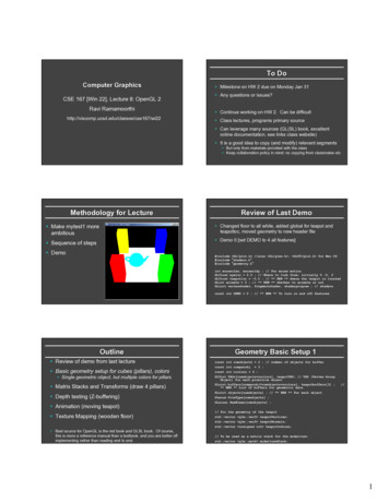
Getting StartedAnalysis CapabilitiesAn Example of Simultaneous Cable Derating, Short Circuit, and Load Flow StudiesOperation Technology, Inc.5ETAP 14 Demo
Getting StartedAnalysis Capabilities2.2 Program Features Five levels of automatic error checkingDynamic help line and error messagingMessage logger to track program usage and accessMultiple user access levelsODBC (open database connectivity)Manages maintenance data via info, remarks, and comment pagesMerge independent ETAP project filesIntegrated 1-phase, 3-phase, and DC systemsIntegrated one-line diagram and underground raceway systemsIntegrated one-line diagram and device coordination/selectivity moduleCommon database for all studiesSimplicity in data entryMultiple subsystems and swing machinesUser-controlled auto save and transactionUser-controlled default settings for all componentsTypical data for motors, generators, transformers, reactors, governors, and excitersIndividual LTC time delays (initial and operating)No voltage limitationsUnlimited protective and metering device connections to branches and loadsUnlimited load connections to a single busAny system frequencyEnglish and metric unit systems25 character component IDsRaw manufacturer data entryIndividual and global load demand and diversity factorsTemperature sensitive cable resistance for all studiesElement navigatorLumped loadingEquipment cables for loads, eliminating requirement for terminal busesEdited by and checked by data stampingDate stamping of all data changesIntelligent editors with user-defined data fieldsAnalysis-dependent data entry requirementsMultiple user network supportCompatible database with the ETAP Real-Time module’s real-time monitoring, simulation, andsupervisory control (Real-Time module is not active in the Demo)Operation Technology, Inc.6ETAP 14 Demo
Getting StartedAnalysis Capabilities2.3 One-Line DiagramsETAP provides a fully graphical editor to construct your one-line diagram. From the One-Line DiagramEdit toolbar, you can graphically add, delete, undo, redo, move, or connect elements; zoom in or out;display grid on or off; change element size, orientation, alignment, symbol, or visibility; enter properties;set operating status; etc.You can use composite networks and motors with unlimited nesting capabilities to create uncluttered andeasy to follow one-line diagrams.Composite networks allow up to 20connections from outside the network,making them very flexible so they can beused in a variety of configurations.Note that the nesting capabilities of a oneline diagram do not affect the calculationresults in any way. Calculation programsconsider all one-line diagram componentsnested to any level.Operation Technology, Inc.7ETAP 14 Demo
Getting StartedAnalysis Capabilities2.4 One-Line Diagram Features AutobuildDatablockData ManagerGround grid systemsMultiple loading categories (conditions) with individual percent loadingUnlimited one-line diagram nesting for subsystems, MCCs, etc.Simultaneous view of one-line diagram presentationsSimultaneous view of system configurationsSimultaneous view of different study resultsOne-Line Diagram TemplatesAuto-SelectSymbols Quick PickPhase adaptersAutomatic bus insertionFind elements from editors or the project windowGrouping/ungrouping of elementsChange size, symbol, orientation, and alignment of elements, individually and globallyActiveX (programmable objects)Graphically fault/clear fault from busesSelectable zoom-to-fitState-of-the-art built-in graphic user interfaceDrag-and-drop, cut and paste, undo and redo, zooming, etc.Built-in ETAP CAD systemXML data exchangeExport one-line diagrams to third party CAD systems via DXF and metafile formatsImport OLE objects (text, pictures, spreadsheets, GIS maps, etc.)Import ETAP DOS project filesImport ASCII project filesExecute external programsCustomizable graphical display of results annotationsCustomizable graphical display of nameplate data annotationsInterchangeable ANSI and IEC element symbolsMultiple sizing and rotation of element symbolsMulti-color symbols and annotationsSupports True Type fontsHide and show protective devices per presentationRemote connectorsGraphical operation (open/close) of switching devices in edit or study modesDisplay of fixed tap and load tap changer (LTC) positions on the one-line diagramDirect device coordination from the one-line diagramComprehensive printing/plotting capabilitiesIndividual and global section of elements, objects, and compositesSchedule manager for system componentsCustomizable output reports (Crystal Reports)ASCII output reportsOperation Technology, Inc.8ETAP 14 Demo
Getting Started Analysis CapabilitiesOutput report manager for both ASCII files and Crystal ReportsAccess database output reportsCrystal Reports for all library dataComprehensive summary reportsCustomizable output plotsReport status of loads and protective devices for all configurationsSystem dumpster with unlimited cells for storage and retrieval of deleted componentsResizable, floating/attachable toolbars for each studyKeyboard ShortcutsOperation Technology, Inc.9ETAP 14 Demo
Getting StartedAnalysis Capabilities2.5 3-D DatabaseETAP uses a 3-D database concept to implement presentations, configurations, and revision data. The useof this multi-dimensional database concept allows you to independently select a particular presentation,status configuration, or revision data within the same project database. PresentationsUnlimited, independent graphical presentations of the one-line diagram to represent the one-linediagrams for any purpose such as impedance diagram, study results, relay diagrams, plot plan,etc. Configurations (Status)Unlimited, independent system configurations to keep track of the status of switching devices(open and closed), motors and loads (continuous, intermittent, and spare), MOVs (open, closed,throttling, and spare).Revision Data (Engineering Properties)Base data and unlimited Revision data to keep track of changes and modifications of theengineering properties (nameplate, settings, etc.) of elements.These three system components are organized in an orthogonal fashion to provide you with great powerand flexibility in constructing and manipulating your ETAP project. Using the concept of Presentation,Status Configuration, and Revision Data, you can create numerous combinations of networks of diverseconfigurations and varying engineering properties that allow you to fully investigate and study thebehavior and characteristics of the electrical networks using one database. This means that there is noneed to copy your database for different system configurations, ‘what if’ studies, on DataThese dimensions can be used in conjunction with multiple loading categories and multiple study cases toquickly and efficiently perform system design and analysis without the possibility of data discrepanciescaused by multiple copies of a single project file being used to account for various system changes.This powerful new concept is unique to ETAP. A 3-D database vs. a flat database means: No need to keep multiple copies of the database Eliminate data discrepancies & errors Higher capability & flexibility Higher productivity Less man-hoursOperation Technology, Inc.10ETAP 14 Demo
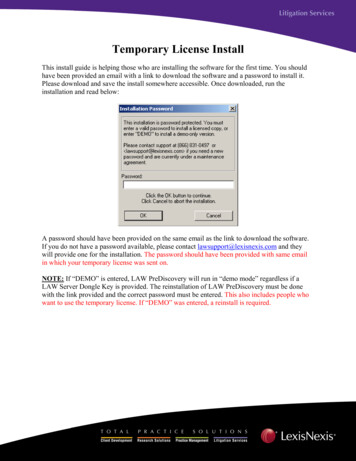
Getting StartedAnalysis Capabilities2.6 PresentationsTwo Graphical Presentations of the Systemwith Different Annotations, Symbols, Locations, and Visibility of ElementsOperation Technology, Inc.11ETAP 14 Demo
Getting StartedAnalysis Capabilities2.7 Configurations (Status)One-Line Diagram with Status Configuration “Stage 1” Active(Note that the single throw switch is open)Operation Technology, Inc.12ETAP 14 Demo
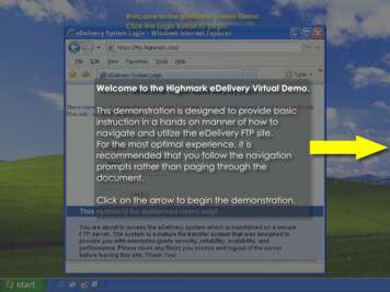
Getting StartedAnalysis Capabilities2.8 Revision Data (Engineering Properties)Base Data Indicating EngineeringProperties of the Existing SystemRevision Data Indicating ModificationsOf Transformer RatingsOperation Technology, Inc.13ETAP 14 Demo
Getting StartedAnalysis Capabilities2.9 ETAP WizardsETAP includes time-saving project management tools called the ETAP Wizards, which allow you torecord and run any study at any time. The ETAP Wizards include the Scenario Wizard, Study Wizard,and Project Wizard. All three are described below.Through the ETAP Wizards, you will be able to combine the orthogonal tools (Presentations,Configurations, and Revision Data), study types, output reports, and study cases (the loading andgeneration system operation factors together with solution parameters) to perform a complete systemstudy with the click of a button.The three ETAP Wizards are located on theSystem toolbar.Operation Technology, Inc.14 Scenario Wizard Study Wizard Project WizardETAP 14 Demo
Getting StartedAnalysis Capabilities2.10 Scenario WizardA scenario allows you to group all study options into one place. For this reason, scenarios are usefulanytime you want to record a study to be executed. Every project file contains a Scenario Wizard.Scenarios are created and recorded in the Scenario Wizard and can be run individually at any time. Aproject can have an unlimited number of scenarios. Scenarios are composed of the following parameters: System (Network Analysis or CSD Analysis)Presentation (e.g., one-line diagram, UGS, or CSD)Revision Data (Base or Revision Data)Configuration Status (e.g., Normal, Stage 1, or TSEvents)Study Mode (e.g., Load Flow or Short-Circuit)Study Case (loading and generation system operation factors and solution parameters)Study Type (vary depending on Study Mode)Output Report (vary depending on Study Mode)When you run a scenario in a project, it will automatically create an output report or overwrite an existingreport with the same name.Scenario Wizard EditorYou can create a scenario either by selecting parameters in the Scenario Wizard or by recording optionsyou have already selected for your study in the one-line view.Operation Technology, Inc.15ETAP 14 Demo
Getting StartedAnalysis Capabilities2.11 Study WizardMacros reduce the time it takes to run several scenarios. Every project file contains a Study Wizard. TheStudy Wizard enables you to sequentially group existing scenarios into study macros. You must havecreated the scenarios you want to include in your study macro before you can create the macro. Youcreate the scenarios using the Scenario Wizard. (See the Scenario Wizard section above for moreinformation.)A project may have an unlimited number of study macros. When you run a study macro, all of thescenarios included in it are run, creating or overwriting the output reports just as they would if they wererun individually. For example, you could group scenarios related to load flow or a specific type of loadflow into one study macro.Study Wizard EditorOperation Technology, Inc.16ETAP 14 Demo
Getting StartedAnalysis Capabilities2.12 Project WizardThe Project Wizard is project independent and is saved within the ETAP folder. It enables the user togroup existing study macros into project macros. You should use a project macro when you have severalprojects from which you want to run multiple study macros and their scenarios simultaneously. Thisfeature automates opening and closing project files and individually executing study macros and theirscenarios.Project Wizard EditorOperation Technology, Inc.17ETAP 14 Demo
Getting StartedAnalysis Capabilities2.15 LibrariesETAP provides extensive user-controlled libraries based on actual manufacturer published data. Cable (NEC, ICEA, and manufacturer published data) Cable fire coating (manufacturer published data) Cable fire stop (manufacturer published data) Cable fire wrap (manufacturer published data) Motor nameplate Motor circuit model (single and double cage motors) Motor characteristic model Motor load model Relay (manufacturer published data) Recloser (manufacturer published data) Electronic Controller (manufacturer published data) LV circuit breaker (manufacturer published data) HV circuit breaker (manufacturer published data) Fuse (manufacturer published data) Overload Heater (manufacturer published data) Harmonic (IEEE and manufacturer published data) Motor overload heater (manufacturer published data) Battery Reliability index library Interruption cost library 50,000 device time-current characteristic curves Merge data from different libraries Export library data to Microsoft Access file with report manager and Crystal ReportsOperation Technology, Inc.18ETAP 14 Demo
Getting StartedAnalysis Capabilities2.20 Active Error ViewerETAP provides five levels of error checking. The active error viewer appears when you attempt to run astudy with missing or inappropriate data. Double-click each individual error message to locate and openthe component editor associated with the cause of the error message.A Transformer Editor Activated after Double-Clicking on the ErrorDemo RestrictionsThe active ETAP demonstration program contains limitations not present in the commercial version.These limitations are listed below: The trial period for the demo is 30 days (extendable by contacting ETAP with your Return Code). The one-line diagram may have a maximum of twelve (12) AC buses and ten (10) DC buses. SeeTen (10) Bus Limitation to learn how to remove existing buses to add new ones. The demo is limited to five (5) STAR presentations. Saving is disabled within the demo. Opening projects is limited to the selection provided by ETAP. Printing output reports are restricted to the original example reports included on the Demo CD.However, the displayed results on the one-line diagram and the plots are based on themodifications made. Importing and exporting functions and Project Merge are disabled.Operation Technology, Inc.19ETAP 14 Demo
Getting StartedAnalysis Capabilities New components may be inserted into the one-line diagram except for panels and phase adapters. Existing components may be inserted into the one-line diagram except for panels and phaseadapters. Existing panels have some limitations such as disabled Summary page, Report Manager, Printing,Library Quick Pick Window, and fixed number of circuits. The Underground Raceway Systems (UGS), Cable Pulling, Ground Grid, and UDM GraphicLogic Editor are disabled. Adding and copying in the Library is disabled. Wind Turbine Generator and Photovoltaic Arraylibraries are disabled. Solar Irradiance calculator is disabled.The following modules are functional in the demo: Load Flow Load Analyzer Short Circuit (ANSI and IEC) AC Arc Flash Arc Flash Sequence of Operation* Star Systems (Device Coordination & Short Circuit) Star Sequence of Operation* Motor Acceleration (Dynamic and Static) * Harmonic Analysis (Load Flow and Frequency Scan) * Transient Stability* Unbalanced Load Flow* Open Phase Fault* Optimal Power Flow* DC Load Flow* DC Short-Circuit* DC Arc Flash* DC Arc Flash Report Analyzer Battery Sizing and Discharge* Reliability Assessment* Optimal Capacitor Placement* Contingency Analysis*Modules may be enabled by contacting ETAP with your Return Code. Your Return Code is specifiedwithin all of the Demo Limitation dialog boxes. Return Codes are different for every computer on whichthe demo is installed.The following modules are not functional in the demo: AC & DC Control Syste
ETAP combines the electrical, logical, mechanical, and physical attributes of system elements in the same database. For example, a cable not only contains data representing its electrical properties and physical dimensions, but also information indicating the raceways through which it is routed. Thus, the data for a