Transcription
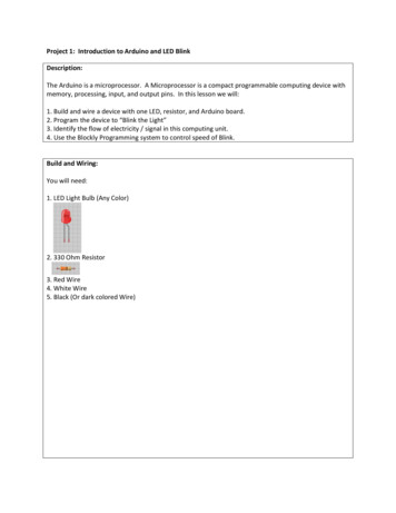
Project 1: Introduction to Arduino and LED BlinkDescription:The Arduino is a microprocessor. A Microprocessor is a compact programmable computing device withmemory, processing, input, and output pins. In this lesson we will:1. Build and wire a device with one LED, resistor, and Arduino board.2. Program the device to “Blink the Light”3. Identify the flow of electricity / signal in this computing unit.4. Use the Blockly Programming system to control speed of Blink.Build and Wiring:You will need:1. LED Light Bulb (Any Color)2. 330 Ohm Resistor3. Red Wire4. White Wire5. Black (Or dark colored Wire)
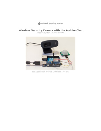
Process:1. Run a red Wire from the 5V Pin to the Red Rail on the Breadboard. This will connect the current sideof the circuit.2. Run a black (or dark colored wire) from the Gnd Pin of the Arduino to the Blue Rail on the far side ofthe Breadboard.
3. Plug an LED bulb into the circuit. Note that the longer pin will face the Arduino Board and the pinsshould cross the “gap” in the breadboard. (Plug the Long Pin into F5 and the Short Pin into E5).4. This step is VERY IMPORTANT!!! Plug a 330 OHM resistor from Port B5 to Ground (The blue rail). AnLED bulb must ALWAYS have a Resistor in the circuit. If we do not use a Resistor, we will burn out thebulb or the Arduino Board.
5. Now we will run the signal wire. Wire Pin 9 on the Arduino to H5 on the Breadboard. This will carrythe current from the Arduino Pin to the LED and allow the Arduino to switch on and off the LED.6. You are finished! Go on to the next section to program your Arduino.
Blockly Programming:1. Go to the website: ex.html2. We want to define a procedure (write directions) for our Arduino Blinky to switch the light. Click on”Procedures” and drag a procedure block to the screen.
3. We need to name our ‘procedure’. Click on the title block and name the block ‘blink’. (Note that wewill always start procedures with a lower case letter).
4. Click on ‘In/Out’ and drag a ‘DigitalWrite PIN#’ block and place it inside the ‘blink’ block.
5. Our Arduino device has the LED plugged in to Pin 9. So we will change the PIN# to 9:
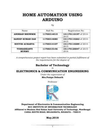
6. ‘HIGH’ means to turn the current on for the Pin. We will leave this set to HIGH. Next, click on‘Control’ and drag a ‘Delay’ block into the ‘blink’ function.
7. We want the LED to blink on for ½ second and off for ½ second. The Delay takes in numbersmeasuring in milliseconds. That means 1000 milliseconds equals 1 second. For ½ a second, we willplace the number 500 in the delay block. Click on ‘Math’ and drag a number block inside the ‘Delay’block.
8. Now type ‘500’ in the Delay block.
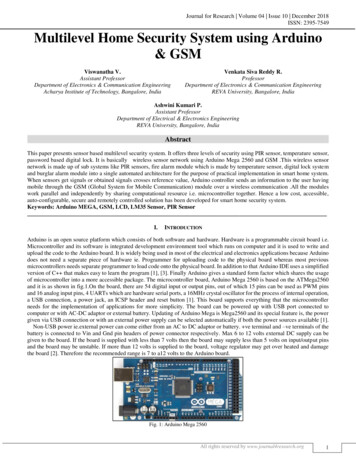
9. This will turn the LED on. Add the following blocks to have the LED turn off. Note that we set thevalue of ‘Stat’ to ‘LOW’ and place another Delay 500 block.
10. We are almost done! We have defined the procedure ‘blink’ and told the Arduino what to do. Nowwe need to tell the Arduino when to run this function. Drag a ‘do blink’ block from the Proceduresmenu and place it on the screen.
11. You are done! Click “Save XML” to save your work. (It will download on your computer.)12. Follow the steps in the next section to download and run your code.
Downloading the Blockly Program to the Arduino1. Click on the Arduino Sketch Icon to start Sketch.2. Plug the Arduino board into the computer’s USB port.3. Go back to the website and click on the ‘Arduino’ tab.
4. When we drag the blocks in the Block view, the website automatically creates the text code to loadinto the Arduino through Sketch. Select all the code in the Arduino tab and right click and select ‘copy’.
5. Go to Arduino Sketch right click. Select “Paste” to put the code into Sketch.
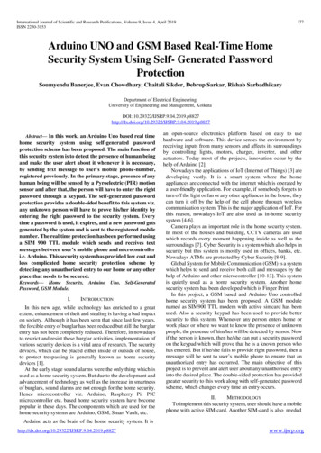
6. Click the Upload Icon to lead the code onto the Arduino. The light should blink!
7. Congratulations! Here are some other ideas to try:a. Change the value of the ‘Delay’ block to control the speed of the blink.b. Create a new procedure ‘blinkFast’ and the following code and watch what happens!
Vocabulary:Arduino Micro-Processor: A mini computer with memory, processing, input, and output. We canprogram this computer to control electrical current and signals to control electric powered devices.Breadboard: Where we can wire electrical circuits and make connections without permanentlysoldering the connections. A test platform for developing electronic devices.Signal: A pulse or pulses of electrical current to carry information. The Arduino uses signals to controlLED’s, speakers, motors, and other devices.Current: A steady state of charge from the positive side of the circuitVolts: The measure of potential energy difference between the positive and negative side of a circuit.Amps: The measure of how much current passes through the circuit in a given length of time.Ground: The source of electrons or the negative side of the circuit.LED: Light Emitting Diode. Acts as a one way gate for current and will emit a light when current ispassed through the LED. LED’s use very little power and are very common in electronic devices. Anylight you see on an electronic device most likely is created by an LED.LED’s have two pins:The Long Pin is wired to the Current side ( side) of the circuit (Anode)The Short Pin is wired to the Ground side (- side) of the circuit (Cathode)Resistor: Resists the flow of current and electrons in a circuit. Measured in Ohms.
We want the LED to blink on for ½ second and off for ½ second. The Delay takes in numbers measuring in milliseconds. That means 1000 milliseconds equals 1 second. For ½ a second, we will place the number 500 in the delay block. Click on ‘Math’ and drag a number block inside the ‘Delay’ block. 8. Now type ‘500’ in the Delay block. 9. This will turn the LED on. Add the following .