Transcription
LLC Resonant AC/DC Switched-ModePower Supply using the MC56F8013and MC56F8257MC56F80xx and MC56F82xx Digital Signal ControllersDocument Number: DRM119Rev. 0
LLC Resonant AC/DC Switched-Mode Power Supply using the MC56F8013 and MC56F8257, Rev. 02Freescale Semiconductor, Inc.General Business Information
ContentsSection numberTitlePageChapter 1Introduction1.1 Application outline.51.2 Resonant converter topologies and features.51.3 Freescale MC56F80xx controller advantages and features.91.4 Freescale MC56F82xx controller advantages and features.12Chapter 2System Description2.1 System concept.172.2 System specification.202.3 Interleaved PFC description.212.4 Resonant converter description.242.5 Synchronous buck converter description.302.6 MC56F80xx high voltage daughter card.332.7 MC56F82xx high voltage daughter card.38Chapter 3Hardware Design3.1 Overview.433.2 Interleaved PFC hardware design.433.2.1 PFC Inductor design.433.2.2 PFC Transistor design.453.2.3 Boost diode design.453.2.4 D.C. Link capacitor tank design.453.3 LLL resonant converter hardware design.463.3.1 LLC resonant converter specification.463.3.2 Resonant network design.473.3.3 Transformer design.48LLC Resonant AC/DC Switched-Mode Power Supply using the MC56F8013 and MC56F8257, Rev. 0Freescale Semiconductor, Inc.3General Business Information
Section numberTitlePage3.4 Synchronous Buck Converter Design.503.4.1 Synchronous buck converter specification.503.4.2 Synchronous buck converter design.503.5 Auxiliary power supply hardware design.51Chapter 4Software Design4.1 Overview.554.2 Primary side software design.554.3 Secondary side software design.594.3.1 MC56F8247/57 Use of Peripherals .604.3.1.1ADC converter.604.3.1.2Quad timer module A channel 0.604.3.1.3Pulse width modulator eFlexPWM sub-module 0.604.3.1.4Pulse width modulator eFlexPWM sub-module 1.604.3.1.5Pulse width modulator eFlexPWM sub-module 2.614.3.1.6High speed comparator HSCMP A and voltage reference VREF A.614.3.1.7High sspeed comparator HSCMP B and voltage reference VREF B.614.3.1.8Serial communication interface SCI 0.614.3.1.9Serial communication interface SCI 1.614.3.1.10 I2C interface IIC 0.624.3.1.11 GPIO pins.624.3.2 Software description.624.3.2.1IsrAdcBComplete() routine.624.3.2.2IsrBuckReload() Routine.634.3.2.3IsrQTA0Compare() Routine.634.3.2.4Background loop.644.3.2.5Application state machine.64LLC Resonant AC/DC Switched-Mode Power Supply using the MC56F8013 and MC56F8257, Rev. 04Freescale Semiconductor, Inc.General Business Information
Chapter 1Introduction1.1 Application outlineThis reference design describes an off-line AC/DC switched-mode power supply (SMPS)using an LLC resonant converter topology.This document focuses on the digital control of key parts of the off-line AC/DC SMPSsystem. It includes control of a power factor correction (PFC), a DC/DC LLC resonantconverter, and a DC/DC buck converter. The AC/DC switch mode power supply is fullydigitally controlled. The digital control is based on two Freescale digital signalcontrollers (DSC). The primary side (PFC) is controlled by the MC56F8013 DSC and thesecondary side, the LLC resonant converter and buck converter is controlled by theMC56F8257 DSC.The reference design incorporates both hardware and software parts of the systemincluding hardware schematics.1.2 Resonant converter topologies and featuresThe off-line AC/DC switched-mode power supplies uses a large number of circuittopologies (flyback, forward, push-pull, boost, buck, half bridge, full bridge, and so on).The circuit topology selection depends on many parameters like output power, inputvoltage, output/input voltage ratio, and so on. The selected circuit topology is alsocompromised in the size, price, and efficiency.The demand for increasing power density of switched-mode power supplies pushesdesigners to use a higher switching frequency. But a very high switching frequencysignificantly increases switching losses at pulse width modulated (PWM) converters. Itbrings decreasing efficiency and also the space saved by using smaller passivecomponents is wasted by larger heating or forced cooling. Therefore the SMPS designersare looking for solutions for decreasing switching losses.LLC Resonant AC/DC Switched-Mode Power Supply using the MC56F8013 and MC56F8257, Rev. 0Freescale Semiconductor, Inc.5General Business Information
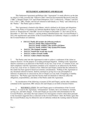
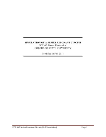
Resonant converter topologies and featuresVindcsourceCfResonantCircuit -VoRLLoadSwitchesRectifierFilterFigure 1-1. Resonant converter principleOne of the possible solutions is the use of resonant converter topologies. The resonantconverter uses a resonant circuit in the conversion path. The typical structure of theresonant converter can be seen in Figure 1-1. The switching network generates a squarewave voltage output with a 50% duty cycle. This voltage pattern feeds the resonant tank.The resonant tank consists of a serial or a parallel combination of L and C passivecomponents. There are several combinations of two or three L and C passive componentsused in the resonant tank. The type of resonant tank and its connection to the load definesthe resonant converter behaviors. Due to the resonant tank, the semiconductor switchescan operate at zero voltage or current switching condition. This phenomenon significantlyreduces switching losses and allows the converter operation at high switchingfrequencies.The most common known resonant topologies are a serial resonant converter (SRC) andparallel resonant converter (PRC). The serial resonant converter can be seen in Figure1-2. The resonant tank consists of a serial connected inductor Lr and capacitor Cr. Theload RL is also connected in series with the resonant tank. In the serial resonant converter,the resonant tank and load creates a voltage divider. Because the resonant tank impedanceis frequency dependent, the output voltage of the serial resonant converter can becontrolled by switching frequency. At the DC or low switching frequency the resonanttank has high impedance in comparison with the load impedance and the output voltage islow. Increasing the switch frequency also increases the output voltage. At the resonantfrequency, the voltage drop on the resonant tank is equal to zero and thus the outputvoltages are equal to the the input voltage. Continuing over the resonant frequency theoutput voltage starts to decrease, this is because the resonant tank impedance increasesagainst to load impedance. The operation over the resonant frequency is preferred, even ifthe output voltage regulation is possible both over or below resonant frequency. Theinductive character of the resonant frequency allows to achieve zero voltage switching(ZVS), which is preferred for MOSFET transistors.LLC Resonant AC/DC Switched-Mode Power Supply using the MC56F8013 and MC56F8257, Rev. 06Freescale Semiconductor, Inc.General Business Information
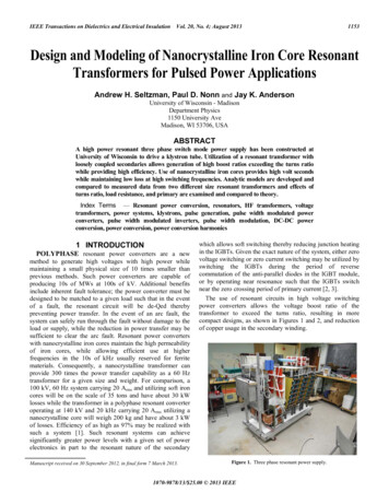
Chapter 1 IntroductionLrCrVin -CfVoRLFigure 1-2. Serial resonant converter topology (SRC)The output voltage regulation is also limited by the load value. If the load is very low, theload impedance is high in comparison with the resonant tank. To keep the desired voltageat the output becomes difficult. Theoretically the switching frequency can be infinite, butpractically there is some maximal frequency limit. Therefore the output voltageregulation at light or no load condition is very limited.LrVinCr -CfVoRLFigure 1-3. Parallel resonant converter topology (PRC)Another well know topology — Parallel resonant converter can be seen in Figure 1-3.The parallel converter uses the same resonant tank as the serial resonant converter, theserial connection of inductor Lr and capacitor Cr. The parallel resonant converter differsin load connection to the resonant tank. In this case, the load is connected in parallel withthe capacitor Cr. In this configuration the voltage divider consists of impedance of theinductor Lr and impedance of parallel combination of the capacitor Cr and the load RL.This means that both parts top and bottom impedance of the voltage divider are frequencydependent. At DC or low switching the output voltage of the parallel resonant converteris equal to input voltages. Increasing the switching frequency the output voltage alsoLLC Resonant AC/DC Switched-Mode Power Supply using the MC56F8013 and MC56F8257, Rev. 0Freescale Semiconductor, Inc.7General Business Information
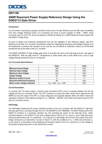
Resonant converter topologies and featuresincreases due to the characteristic of the resonant tank. The maximal output voltage isachieved at a resonant frequency, where the output voltage is Q times higher than theinput voltage. The Q is a quality factor of the resonant tank. Over the resonant frequencythe output voltage falls, because the inductor impedance becomes more dominant againstthe capacitor impedance.The parallel resonant converter can control the output voltage even at no load conditions.In this case the load is comprised of a resonant tank only. On the other hand, thepermanent connection of the resonant tank to the switch network brings some drawbacksat nominal operation. At nominal load the parallel converter operates close to theresonant frequency and thus the resonant tanks have the lowest impedance. This alsomeans a high circulating current through the resonant tank. The parallel converter alsooperates over the resonant frequency due to ZVS conditions.CrLrVin -LmCfVoRLFigure 1-4. LLC resonant converter topologyOther than the two part resonant tanks, there are almost 40 possibilities of three partresonant tanks. The most popular member of three part tanks is the LLC resonantconverter. The resonant tank consists of two inductors Lr, Lm and one capacitor Cr (seeFigure 1-4). The load is connected in parallel to the inductor Lm. The LLC resonantconverter solves all drawbacks mentioned above. At no load conditions the outputvoltage can still be controlled by a voltage drop over inductor Lm. Also at resonantfrequency the current is limited by the Lm inductor, therefore the circulating currentthrough the resonant circuit can be kept on an acceptable level. Another advantage of theLLC resonant converter is that it can operate under ZVS condition over the whole loadLLC Resonant AC/DC Switched-Mode Power Supply using the MC56F8013 and MC56F8257, Rev. 08Freescale Semiconductor, Inc.General Business Information
Chapter 1 Introductionrange. The behaviors of the LLC resonant converter will be discussed in more detail inthe Section Resonant converter description. The summary of the key features of all thementioned resonant converters can be seen in Table 1-1.Table 1-1. Resonant converters comparisonSRCZVS operationOperation without loadOperation at frOperation at wide input rangePRCLLCAbove fr onlyAbove fr onlyYesNoYes, but high lossesYesNo (close to fr)No (close to fr)YesHigh lossesHigh lossesYes1.3 Freescale MC56F80xx controller advantages and featuresThe Freescale MC56F80xx family is suited for switch mode power supplies (SMPS)control, motor control, and combining the DSP's calculation capability with the MCU'scontroller features on a single chip. These hybrid controllers offer many dedicatedperipherals such as pulse width modulation (PWM) modules, analogue-to-digitalconverters (ADC), timers, communication peripherals (SCI, SPI, I2C), and on-board flashand RAM.The MC56F80xx family provides the following peripheral blocks: One PWM module with PWM outputs, fault inputs, fault-tolerant design with deadtime insertion, supporting center-aligned, and edge-aligned modes 12-bit ADC, supports two simultaneous conversions; ADC and PWM modules canby synchronized One dedicated 16-bit general purpose quad timer module One serial peripheral interface (SPI) One serial communication interface (SCI) with LIN slave functionality On-board 3.3 V to 2.5 V voltage regulator for powering internal logic and memories Integrated power on reset and low-voltage interrupt module All pins multiplexed with general purpose input/output (GPIO) pins Computer operating properly (COP) watchdog timer External reset input pin for hardware resetLLC Resonant AC/DC Switched-Mode Power Supply using the MC56F8013 and MC56F8257, Rev. 0Freescale Semiconductor, Inc.9General Business Information
Freescale MC56F80xx controller advantages and features JTAG/On-Chip Emulation (OnCETM) module for unobtrusive processor-speedindependent debugging Phase-locked loop (PLL) based frequency synthesizer for the hybrid controller coreclock with on-chip relaxation oscillatorTable 1-2. MemoryconfigurationMemory TypeMC56F8013Program flash16 KbyteUnified data/program RAM4 KbyteThe SMPS and motor control benefit from the flexible PWM module, fast ADC, andquad timer module.The PWM offers flexibility in its configuration, enabling an efficient three-phase motorcontrol. The PWM module is capable of generation asymmetric PWM duty cycles in acenter-aligned configuration. The PWM reload SYNC signal can be generated to providesynchronization with other modules (ADC, Quad-timer).The PWM block has the following features: Three complementary PWM signal pairs, six independent PWM signals (or acombination) Complementary channel operation features Independent top and bottom dead time insertion Separate top and bottom pulse width correction via current status inputs or software Separate top and bottom polarity control Edge-aligned or center-aligned PWM reference signals with a 15-bit resolution Half-cycle reload capability Integral reload rates from one to sixteen periods Mask/swap capability Individual, software-controlled PWM output Programmable fault protection Polarity control 10 mA or 16 mA current sink capability on PWM pins Write-protectable registersThe application uses the PWM module for generating two duty cycles for the interleavedboost converter MOSFET transistors.The ADC module has the following features: 12-bit resolution Dual ADCs per module; three input channels per ADCLLC Resonant AC/DC Switched-Mode Power Supply using the MC56F8013 and MC56F8257, Rev. 010Freescale Semiconductor, Inc.General Business Information
Chapter 1 Introduction Maximum ADC clock frequency of 5.33 MHz with a 187 ns periodSampling rate of up to 1.78 million samples per secondSingle conversion time of 8.5 ADC clock cycles (8.5 x 187 ns 1.59 µs)Additional conversion time of six ADC clock cycles ( 6 x 187 ns 1.125 µs)Eight conversion in 26.5 ADC clock cycles (26.5 x 187 ns 4.97 µs) using parallelmodeAbility to use the SYNC input signal to synchronize with the PWM (if the integrationallows the PWM to trigger a timer channel connected to the SYNC input)Ability to sequentially scan and store up to eight measurementsAbility to scan and store up to four measurements on each of two ADCs operatingsimultaneously and in parallelAbility to scan and store up to four measurements on each of two ADCs operatingasynchronously to each other in parallelInterrupt generating capabilities at the end of a scan when an out-of-range limit isexceeded and on a zero crossingOptional sample correction by subtracting a pre-programmed offset valueSigned or unsigned resultsSingle-ended or differential inputsPWM outputs with hysteresis for three of the analogue inputsThe application uses the ADC block in simultaneous mode scan. It is synchronized to theQuadrature timer. This configuration allows the simultaneous conversion of the requiredanalogue values for the input current, input voltage, and output voltage within therequired time.The Quadrature timer is an extremely flexible module, providing all required servicesrelating to time events. It has the following features: Four 16-bit counters/timersCount up/downCounters are cascadableProgrammable count modulusFour 16-bit counters/timersMaximum count rate equal to the peripheral clock/2, when counting external eventsMaximum count rate equal to the peripheral clock/1, when using internal clocksCount once or repeatedlyCounters are preloadableCounters can share available input pinsEach counter has as separate precalerFour 16-bit counters/timersEach counter has a capture and compare capabilityLLC Resonant AC/DC Switched-Mode Power Supply using the MC56F8013 and MC56F8257, Rev. 0Freescale Semiconductor, Inc.11General Business Information
Freescale MC56F82xx controller advantages and featuresThe application uses two channels of the quad timer for synchronization PWM to ADCand one channel for application timing.1.4 Freescale MC56F82xx controller advantages and featuresThe MC56F825x/MC56F824x is a member of the 56800E core-based family of digitalsignal controllers (DSCs). It combines on a single chip, the processing power of a DSP,and the functionality of a microcontroller with a flexible set of peripherals to create acost-effective solution. Because of its low cost, configuration flexibility, and compactprogram code, it is well-suited for many applications. The MC56F825x/MC56F824xincludes many peripherals that are especially useful for cost-sensitive applications, likeindustrial control, home appliances, solar inverters, battery chargers and management,switched–mode power supplies and power management, power metering, motor control(ACIM, BLDC, PMSM, SR, and stepper), and others.The MC56F825x/MC56F824x family provides the following on-chip features: 60 MHz operation frequency DSP and MCU functionality in a unified, C-efficient architecture On-chip memory 56F8245/46 — 48 KB (24K x 16) flash memory; 6 KB (3K x 16) unified data/program RAM 56F8247 — 48 KB (24K x 16) flash memory; 8 KB (4K x 16) unified data/program RAM 56F8255/56/57 — 64 KB (32K x 16) flash memory; 8 KB (4K x 16) unifieddata/program RAM eFlexPWM with up to 9 channels, including 6 channels with high (520 ps) resolutionNanoEdge placement Two 8-channel, 12-bit analog-to-digital converters (ADCs) with dynamic x2 and x4programmable amplifier, conversion time as short as 600 ns, and input currentinjection protection Three analog comparators with integrated 5-bit DAC references Cyclic Redundancy Check (CRC) Generator Two high-speed queued serial communication interface (QSCI) modules with LINslave functionality Queued serial peripheral interface (QSPI) module Two SMBus–compatible inter-integrated circuit (I2C) ports Freescale’s scalable controller area network (MSCAN) 2.0 A/B module Two 16-bit quad timers (2 x 4 16-bit timers) Computer operating properly (COP) watchdog module On-chip relaxation oscillator — 8 MHz (400 kHz at standby mode)LLC Resonant AC/DC Switched-Mode Power Supply using the MC56F8013 and MC56F8257, Rev. 012Freescale Semiconductor, Inc.General Business Information
Chapter 1 Introduction Crystal/resonator oscillator Integrated power-on reset (POR) and low-voltage interrupt (LVI) and brown-outreset module Inter-module crossbar connection Up to 54 GPIOs 44-pin LQFP, 48-pin LQFP, and 64-pin LQFP packages Single supply — 3.0 V to 3.6 VThe switched-mode power supply applications benefit greatly from the flexibleeFlexPWM module, fast ADC module, on-chip analog comparator module, and intermodule crossbar.The Enhanced Flex Pulse Width Modulator (eFlexPWM) module has the followingfeatures: Up to nine output channels 16 bits of resolution for center, edge aligned, and asymmetrical PWMs Each complementary pair can operate with its own PWM frequency based anddeadtime values 4 time base Independent top and bottom deadtime insertion PWM outputs can operate as complimentary pairs or independent channels Independent control of both edges of each PWM output 6-channel NanoEdge high resolution PWM Fractional delay for enhanced resolution of the PWM period and edge placement Arbitrary eFlexPWM edge placement — PWM phase shifting NanoEdge implementation— 520 ps PWM frequency resolution 3 Channel PWM with full input capture features Three PWM Channels — PWMA, PWMB, and PWMX Enhanced input capture functionality Synchronization to external hardware or other PWM supported Double buffered PWM registers Integral reload rates from 1 to 16 Half cycle reload capability Multiple output trigger events can be generated per PWM cycle via hardware Support for double switching PWM outputs Up to four fault inputs can be assigned to control multiple PWM outputs Programmable filters for fault inputs Independently programmable PWM output polarity Individual software-control for each PWM output All outputs can be programmed to change simultaneously via a FORCE OUT event PWMX pin can optionally output a third PWM signal from each submoduleLLC Resonant AC/DC Switched-Mode Power Supply using the MC56F8013 and MC56F8257, Rev. 0Freescale Semiconductor, Inc.13General Business Information
Freescale MC56F82xx controller advantages and features Channels not used for PWM generation can be used for buffered output comparefunctions Channels not used for PWM generation can be used for input capture functions Enhanced dual edge capture functionality The option to supply the source for each complementary PWM signal pair from anyof the following: Crossbar module outputs External ADC input, taking into account values set in ADC high and low limitregistersThe eFlexPWM offers flexibility in its configuration, enabling efficient control of anySMPS topology. The eFlexPWM module is capable of free control of rising and fallingedges for each PWM output and includes automatic complementary signal generation anddead time insertion. Due to NanoEdge placement the eFlexPWM can generate dutycycles and frequencies with high a resolution of up to 520 ps. The eFlexPWM modulecan also generate up to 6 synchronization events per sub-module to providesynchronization with other modules (ADC, Quad-timer).The application uses the eFlexPWM module for generating four PWM signals for LLCresonant converter and two PWM signals for synchronous buck converter. The PWMsignals for the LLC converter have a variable frequency and constant duty cycle at 50 %.The synchronous buck PWM signals have a fixed frequency of 500 kHz and variableduty cycle.The ADC converter has the following features: Two independent 12-bit analog-to-digital converters (ADCs) 2 x 8 channel external inputs Built-in x1, x2, x 4 programmable gain pre-amplifier Maximum ADC clock frequency — Up to 10 MHz Single conversion time of 8.5 ADC clock cycles (8.5 x 100 ns 850 ns) Additional conversion time of 6-ADC clock cycles (6 x 100 ns 600 ns) Sequential, parallel, and independent scan mode First 8 samples have Offset, Limit, and zero-crossing calculation supported ADC conversions can be synchronized by eFlexPWM and timer modules via theinternal crossbar module Support for simultaneous and software triggering conversions Support for multi-triggering mode with a number of programmable conversions oneach triggerLLC Resonant AC/DC Switched-Mode Power Supply using the MC56F8013 and MC56F8257, Rev. 014Freescale Semiconductor, Inc.General Business Information
Chapter 1 IntroductionThe application uses the ADC module in independent scan mode. The first ADCconverter is synchronized with LLC resonant converter PWM signals. It samples outputvoltage and output current of LLC resonant converter. The second ADC converter issynchronized with synchronous buck PWM signals and converts output voltage andoutput current of synchronous buck converter.The Inter-Module Crossbar Switch (XBAR) has the following features: Programmable internal module connections between and among the eFlexPWM,ADCs, Quad Timers, 12-bit DAC, HSCMPs, and package pins User-defined input/output pins for PWM fault inputs, timer input/output, ADCtriggers, and comparator outputsThe application uses the inter-module crossbar switch to provide interconnection betweenthe eFlexPWM module and ADC module, interconnection between the input pin (faultsignal) and on-chip comparator, and interconnection between comparator's output andeFlexPWM fault input.The application also uses other peripherals like a QTimer module for the software timer,the I2C module for communication with the temperature sensor, 2xSCI module forcommunication with the primary side and remote control via PC, the SPI module forcommunication via the SMBUS, and the MSCAN module for communication via CANbus.LLC Resonant AC/DC Switched-Mode Power Supply using the MC56F8013 and MC56F8257, Rev. 0Freescale Semiconductor, Inc.15General Business Information
Freescale MC56F82xx controller
The AC/DC switch mode power supply is fully digitally controlled. The digital control is based on two Freescale digital signal controllers (DSC). The primary side (PFC) is controlled by the MC56F8013 DSC and the secondary side, the LLC r