Transcription
Introduction to ArduinoA piece of cake!by Alan G. SmithSeptember 30, 2011
Cover Photo Credit: Arduino CakeCopyright 2011 Alan G. Smith.All Rights Reserved.Cake made by Lisa Smith and familyIntroduction to Arduino: A piece of cake!Copyright 2011 Alan G. Smith. All Rights Reserved.The author can be contacted at: alan@introtoarduino.comThe hardcopy of the book can be purchased from http://www.amazon.comThe most recent PDF is free at http://www.introtoarduino.comISBN: 1463698348ISBN-13: 978-1463698348
This book is dedicated to:My wife who first encouraged me to teach this class andthen put up with my spending countless hours on this bookand also helped with numerous comments on the firstproof.My children who excite me about teaching.My father who spent many hours with me on the Vic 20,Commodore 64, and the robotic arm science project.Without his investment, I wouldn’t be the engineer I amtoday.All who would desire to make something, may this bookhelp you with your inventions.Whatever you do, work at it with all your heart, as working forthe Lord, not for men.Colossians 3:23 (NIV 1984)
Contents1Getting Started1.11.21.31.41.51.61.71.81.92. 1. 3. 5. 7. 9. 9. 12. 13. 14Making Light Patterns2.12.22.32.42.52.62.72.82.92.1031What is a Microcontroller? . . . . . . . . . . . . .Install the Software . . . . . . . . . . . . . . . . .The Integrated Development Environment (IDE)Our first circuit . . . . . . . . . . . . . . . . . . .Updated Circuit . . . . . . . . . . . . . . . . . . .Our First Program . . . . . . . . . . . . . . . . .Comments . . . . . . . . . . . . . . . . . . . . . .Gotchas . . . . . . . . . . . . . . . . . . . . . . . .Exercises . . . . . . . . . . . . . . . . . . . . . . .Input3.13.23.3“Blinky” . . . . . .IF Statements . . .ELSE Statements .WHILE statementsWhat is truth(true)?Combinations . . .FOR statements . .Our New Circuit .Introducing ArraysExercises . . . . . .17.1717202122242526293133Pushbuttons . . . . . . . . . . . . . . . . . . . . . . . . . . . . . . . 33Potentiometers . . . . . . . . . . . . . . . . . . . . . . . . . . . . . . 41RGB LEDs . . . . . . . . . . . . . . . . . . . . . . . . . . . . . . . . 46v
Contents3.44Sound4.14.24.34.44.55.Serial Monitor . . . . . . . .Measuring the temperatureHooking up the LCD . . . .Talking to the LCD . . . . .Bringing it all together . . .Exercises . . . . . . . . . . .Introduction . . . . . . . . . . . . . . .Photo Cell (Light Sensor) . . . . . . . .Tilt Sensor . . . . . . . . . . . . . . . .Reed Switch (Magnetic Field Detector)Piezo Element (Vibration sensor) . . .Exercises . . . . . . . . . . . . . . . . .Binary and HexUsing graphics .Making a ChartExercises . . . .Making a rubber band gun8.18.28.3vi.515253555859.59626668717375.Sensors Galore7.17.27.37.47.57.68.Graphics (Pictures) on our LCD6.16.26.36.4751Our Circuit . . . . . .Simple note . . . . .Music . . . . . . . . .Music with functionsExercises . . . . . . .Making a digital thermometer5.15.25.35.45.55.66Exercises . . . . . . . . . . . . . . . . . . . . . . . . . . . . . . . . . 49757782899191919395969899One Servo . . . . . . . . . . . . . . . . . . . . . . . . . . . . . . . . 99Joystick . . . . . . . . . . . . . . . . . . . . . . . . . . . . . . . . . . 101Pan/Tilt bracket . . . . . . . . . . . . . . . . . . . . . . . . . . . . . 103
Contents8.48.59Adding a firing mechanism . . . . . . . . . . . . . . . . . . . . . . 106Exercises . . . . . . . . . . . . . . . . . . . . . . . . . . . . . . . . . 110Make your own project!11110 Next Steps113A Arduino ReferenceA.1A.2A.3A.4115Structure . . . . . . . . . . . . . . .Variables . . . . . . . . . . . . . . .Functions . . . . . . . . . . . . . . .PCD8544 (LCD Controller) 9156160B Parts in KitB.1B.2B.3B.4B.5B.6B.7B.8127First used in Chapter 1First used in Chapter 2First used in Chapter 3First used in Chapter 4First used in Chapter 5First used in Chapter 6First used in Chapter 7First used in Chapter 8.C Sample Solutions to Selected ExercisesC.1C.2C.3C.4C.5C.6C.7C.8Chapter 1 SolutionsChapter 2 SolutionsChapter 3 SolutionsChapter 4 SolutionsChapter 5 SolutionsChapter 6 SolutionsChapter 7 SolutionsChapter 8 Solutions116120121125.131vii
Listings1.11.21.3Simplest Program . . . . . . . . . . . . . . . . . . . . . . . . . . . . 9led1/led1.pde . . . . . . . . . . . . . . . . . . . . . . . . . . . . . . 10Blink/Blink.pde . . . . . . . . . . . . . . . . . . . . . . . . . . . . . 122.12.22.32.42.52.6blink if/blink if.pde . . . . . . . .blink else/blink else.pde . . . . .blink while/blink while.pde . . .blink for/blink for.pde . . . . . .lightPattern1/lightPattern1.pde . 3.23.33.43.53.63.7button1/button1.pde . .button2/button2.pde . .Constrain . . . . . . . . .pot1/pot1.pde . . . . . .pot2/pot2.pde . . . . . .pot3/pot3.pde . . . . . .rgb 3pot/rgb 3pot.pde.353940424444484.14.24.34.4sound simple/sound simple.pdesound 2/sound 2.pde . . . . . . .sound 3/sound 3.pde . . . . . . .sound array/sound array.pde . .525456575.15.25.35.4blink if serial/blink if serial.pdetemp serial/temp serial.pde . . .lcd1/lcd1.pde . . . . . . . . . . . .temp lcd/temp lcd.pde . . . . . .59636971.ix
Listingsx6.16.2temp lcd graphic/temp lcd graphic.pde . . . . . . . . . . . . . . 79temp lcd graphic chart/temp lcd graphic chart.pde . . . . . . ltsensor.pdereed1/reed1.pde . . . . .knock1/knock1.pde . . .929495978.18.28.38.4servo1/servo1.pde . . . . . . . . . . .joystick/joystick.pde . . . . . . . . . .pantilt/pantilt.pde . . . . . . . . . . .rubberBandGun/rubberBandGun.pde.100102104108.
Chapter 1Getting StartedThe purpose of this book is to get you started on the road to creating thingsusing micro-controllers. We will discuss only enough electronics for you tomake the circuits, and only enough programming for you to get started. Thefocus will be on your making things. It is my hope that as you go through thisbook you will be flooded with ideas of things that you can make. So let’s getgoing.The first question we’ll start with is:1.1 What is a Microcontroller?Wikipedia1 says:A micro-controller is a small computer on a single integrated circuit containing a processor core, memory, and programmable input/output peripheralsThe important part for us is that a micro-controller contains the processor (whichall computers have) and memory, and some input/output pins that you cancontrol. (often called GPIO - General Purpose Input Output Pins).1 http://en.wikipedia.org/wiki/Microcontroller -17 March 20111
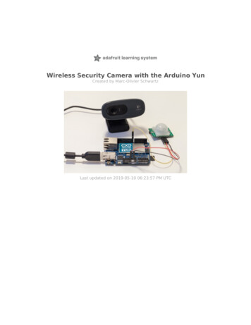
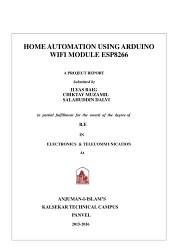
Chapter 1 Getting Started For this book, we will be using the Arduino Uno board. This combines amicro-controller along with all of the extras to make it easy for you to buildand debug your projects. We will be using a breadboard in this book. This is a relatively easy wayto make circuits quickly. Breadboards are made for doing quick experiments.They are not known for keeping circuits together for a long time. When you areready to make a project that you want to stay around for a while, you shouldconsider an alternative method such as wire-wrapping or soldering or evenmaking a printed circuit board (PCB).The first thing you should notice about the breadboard is all of the holes.These are broken up into 2 sets of columns and a set of rows (the rows are2
1.2 Install the Softwaredivided in the middle). The columns are named a, b, c, d, e, f, g, h, i, and j (fromleft to right). The rows are numbered 1 - 30. (from top to bottom). The columnson the edges do not have letters or numbers.The columns on the edges are connected from top to bottom inside of thebreadboard to make it easy to supply power and ground. (You can think ofground as the negative side of a battery and the power as the positive side.)For this book our power will be 5 volts.Inside of the breadboard, the holes in each row are connected up to the breakin the middle of the board. For Example: a1,b1,c1,d1,e1 all have a wire insideof the breadboard to connect them. Then f1, g1, h1, i1, and j1 are all connected.but a1 is not connected to f1. This may sound confusing now, but it will quicklycome to make sense as we wire up circuits.1.2 Install the SoftwareIf you have access to the internet, there are step-by-step directions and the software available at: http://arduino.cc/en/Main/SoftwareOtherwise, the USB stick in your kit2 has the software under the SoftwareDirectory. There are two directories under that. One is “Windows” and theother is “Mac OS X”. If you are installing onto Linux, you will need to followthe directions at: http://arduino.cc/en/Main/Software1.2.1 Windows Installations1. Plug in your board via USB and wait for Windows to begin its driverinstallation process. After a few moments, the process will fail. (This isnot unexpected.)2. Click on the Start Menu, and open up the Control Panel.3. While in the Control Panel, navigate to System and Security. Next, clickon System. Once the System window is up, open the Device Manager.2 Thisbook was originally written to go along with a class. If you have the book, but not thekit go to http://www.introtoarduino.com for more information and all of the sourcecode in this book.3
Chapter 1 Getting Started4. Look under Ports (COM & LPT). You should see an open port named"Arduino UNO (COMxx)".5. Right click on the "Arduino UNO (COMxx)" port and choose the "UpdateDriver Software" option.6. Next, choose the "Browse my computer for Driver software" option.7. Finally, navigate to and select the Uno’s driver file, named "ArduinoUNO.inf",located in the "Drivers" folder of the Arduino Software download (not the"FTDI USB Drivers" sub-directory).8. Windows will finish up the driver installation from there.9. Double-click the Arduino application.10. Open the LED blink example sketch: File Examples 1.Basics Blink11. Select Arduino Uno under the Tools Board menu.12. Select your serial port (if you don’t know which one, disconnect the UNOand the entry that disappears is the right one.)13. Click the Upload button.14. After the message “Done uploading” appears, you should see the “L”LED blinking once a second. (The “L” LED is on the Arduino directlybehind the USB port.)1.2.2 Mac Installation1. Connect the board via USB.2. Drag the Arduino application onto your hard drive.3. When Network Preferences comes up, just click “Apply” (remember the/dev/tty/usb.)4. Start the program.4
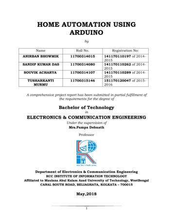
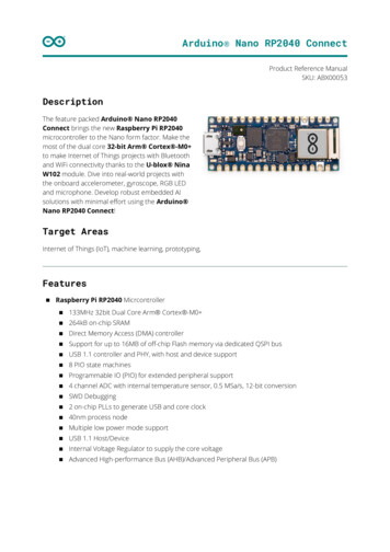
1.3 The Integrated Development Environment (IDE)5. Open the LED blink example sketch: File Examples 1.Basics Blink6. Select Arduino Uno under the Tools Board menu.7. Select your serial port (if you don’t know which one, disconnect the UNOand the entry that disappears is the right one.)8. Click the Upload button.9. After the message “Done uploading” appears, you should see the “L”LED blinking once a second. (The “L” LED is on the Arduino directlybehind the USB connection)1.3 The Integrated Development Environment (IDE)You use the Arduino IDE on your computer (picture following) to create, open,and change sketches (Arduino calls programs “sketches”. We will use the twowords interchangeably in this book.). Sketches define what the board will do.You can either use the buttons along the top of the IDE or the menu items.5
Chapter 1 Getting Started Parts of the IDE: (from left to right, top to bottom) Compile - Before your program “code” can be sent to the board, it needsto be converted into instructions that the board understands. This processis called compiling. Stop - This stops the compilation process. (I have never used this buttonand you probably won’t have a need to either.) Create new Sketch - This opens a new window to create a new sketch. Open Existing Sketch - This loads a sketch from a file on your computer.6
1.4 Our first circuit Save Sketch - This saves the changes to the sketch you are working on. Upload to Board - This compiles and then transmits over the USB cableto your board. Serial Monitor - We will discuss this in section 5.1. Tab Button - This lets you create multiple files in your sketch. This is formore advanced programming than we will do in this class. Sketch Editor - This is where you write or edit sketches Text Console - This shows you what the IDE is currently doing and isalso where error messages display if you make a mistake in typing yourprogram. (often called a syntax error) Line Number - This shows you what line number your cursor is on. It isuseful since the compiler gives error messages with a line number1.4 Our first circuitBefore we get to the programming, let’s connect an LED. LED stands for LightEmitting Diode. A diode only allows electricity to flow through it one way, soif you hook it up backwards it won’t work.If you connect the LED directly to power and ground, too much current willgo through the diode and destroy it. To keep that from happening we will usea resistor to limit the current. You can think of a resistor like a water pipe. Thehigher the value of the resistor is like using a smaller pipe that lets less electricity “flow” through. This is not technically correct, but it is close enough for thisbook. We will use a 330 Ohm (Ohm is often shown as Ω) resistor (Resistance ismeasured in ohms. Resistors have color bands on them that let you know whatvalue they are.3 A 330Ω resistor will have color bands: Orange-Orange-Brown)It doesn’t matter which way you plug in a resistor.The two leads (sometimes called “legs”) of an LED are called an anode anda cathode. The anode is the longer lead. IMPORTANT: IF YOU PLUG IT IN3 Weare not going to talk in this text about how to decide which size resistor to use.7
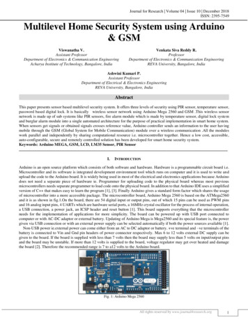
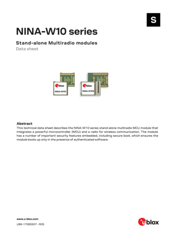
Chapter 1 Getting Started BACKWARDS, IT WILL NOT WORK. (But it won’t be damaged, either. Don’tworry.) 1. With a wire, connect ground from the Arduino (labeled GND) to the bottom row of the farthest right column of the bread board.2. With a wire, connect power from where it says 5V (the V stands for voltage and this is where the electric power comes from.) on the Arduino tothe bottom row of the next to right column.3. Connect the resistor with one end in h2 and the other end on the far rightcolumn (ground).4. Connect the LED cathode (shorter leg) to f2. (This makes it connect to theresistor through the breadboard because they are on the same row.)5. Connect the LED anode (longer leg) to f3.6. Connect a wire from h3 to the next to right column ( 5V).7. Plug power into the Arduino .8. The LED should light up. If it doesn’t, unplug power from the Arduino,check all of your connections and make sure you have not plugged theLED in backwards. Then try power again.Congratulations, you have made your first circuit!8
1.5 Updated Circuit 1.5 Updated Circuit Let’s modify our circuit slightly so that the Arduino will be controlling theLED. Take the wire from h3 and connect it to pin 13 of the Arduino. You coulduse any pin, we are using pin 13 because the default program on the Arduinowhen you first get it blinks the “L” LED which is on pin 13 so we can check ourcircuit without any new software. (You should unplug your Arduino beforemaking changes to the circuit. )1.6 Our First ProgramNow let’s write a program to control the LED. Each program must contain atleast two functions. A function is a series of programming statements that canbe called by name.1. setup() which is called once when the program starts.2. loop() which is called repetitively over and over again as long as theArduino has power.So the shortest valid Arduino program (even though it does nothing) is:Listing 1.1: Simplest Program1void setup()9
Chapter 1 Getting Started23{}4567void loop(){}In most programming languages, you start with a program that simply prints“Hello, World” to the screen. The equivalent in the micro-controller world isgetting a light to blink on and off. This is the simplest program we can write toshow that everything is functioning correctly.(Throughout this book we will show the program (sketch) in its entirety first,and then explain it afterwards. So if you see something that doesn’t make sense,keep reading and hopefully it will be cleared up.)Listing 1.2: led1/led1.pde1const int kPinLed 13;23456void setup(){pinMode(kPinLed, OUTPUT);}7891011121314void loop(){digitalWrite(kPinLed, HIGH);delay(500);digitalWrite(kPinLed, LOW);delay(500);}Here is a breakdown of what this program does.1const int kPinLed 13;This defines a constant that can be used throughout the program instead ofits value. I HIGHLY encourage this for all pins as it makes it easy to changeyour software if you change your circuit. By convention, constants are named10
1.6 Our First Programstarting with the letter k. You don’t have to do this, but it makes it easier whenyou look through your code to know what is a constant.3456void setup(){pinMode(kPinLed, OUTPUT);}This sets up the pin that our LED is connected to as an OUTPUT pin. (Meaning that the Arduino is controlling “writing” to a pin instead of reading fromit.)891011121314void loop(){digitalWrite(kPinLed, HIGH);delay(500);digitalWrite(kPinLed, LOW);delay(500);}These lines are where the action is. We start by writing HIGH out on the pinconnected to the LED which will turn the LED on. (HIGH means putting 5Vout on the pin. The other choice is LOW which means putting 0V out on thepin.)1th of aWe then call delay() which delays the number of milliseconds ( 1000second) sent to it. Since we send the number 500, it will delay for ½ second.We then turn the LED off by writing LOW out on the pin.We delay for 500 milliseconds (½ second)This will continue until power is removed from the Arduino.Before we go any further, try this on your Arduino and make sure it works.(there is an LED on the UNO board that is connected to pin 13 so if it blinksand your LED on the breadboard doesn’t, then you probably put your LED inbackwards.) You will know this works because this blinks the LED twice as fastas the original program that is on your Arduino. If it blinks once a second, thenyou have not successfully sent your new program to the Arduino.11
Chapter 1 Getting Started1.7 CommentsSo far our programs have been only for the computer. But it turns out thatyou can put things in them that are only for the human readers. You can (andshould) add comments to the program which the computer ignores and are forhuman readers only. This language supports two forms of comments:1. The block comment style. It starts with a /* and continues until a */ isencountered. This can cross multiple lines. Below are three examples./* This is a comment *//* So is this *//* And* this* as* well */2. A single line comment. It starts with a // and tells the computer to ignorethe rest of the line.// This is also a commentHere is an example of what our earlier program might look like with comments added:(In this and all other code listings in this book, if a number doesn’t show nextto the line then it means it is a continuation of the line above but our paper isn’twide enough to show the entire thing. You will see an arrow at the end of theline that is to be continued and another arrow on the continuation line. That isjust for this book, you will not see them in the IDE and you don’t need to typethem in.Listing 1.3: Blink/Blink.pde12/** Program Name: Blink12
1.8 Gotchas34567* Author: Alan Smith* Date Written: 17 March 2011* Description:Turns an LED on for one half second, then off for one !*" half second repeatedly.*/8910/* Pin Definitions */const int kPinLed 13;111213141516171819/** Function Name: setup* Purpose: Run once when the system powers up.*/void setup(){pinMode(kPinLed, OUTPUT);}202122232425262728293031/** Function name: loop* Purpose: Runs over and over again, as long as the Arduino !" has power*/void loop(){digitalWrite(kPinLed, HIGH);delay(500);digitalWrite(kPinLed, LOW);delay(500);}1.8 GotchasIf your program won’t compile (or it doesn’t do what you expect), here are afew things to check that often confuse people:13
Chapter 1 Getting Started The programming language is case sensitive. In other words, myVar isdifferent than MyVar Whitespace (spaces, tabs, blank lines) is all collapsed to the equivalent ofa single space. It is for the human reader only. Blocks of code are encapsulated with curly braces ’{’ and ’}’ Every open parenthesis ’(’ must have a matching close parenthesis ’)’ There are no commas in numbers. So you must say 1000 and NOT1,000. Each program statement needs to end with a semicolon ’;’. In general,this means that each line of your program will have a semicolon. Exceptions are:– Semicolons (like everything) are ignored in comments– Semicolons are not used after the end curly brace. ’}’1.9 Exercises(There are sample solutions in Appendix C. However, you should struggle withthem first and only look there when you are stuck. If you end up looking there,you should make up another exercise for yourself. The Challenge exercises donot have sample solutions.)1. Change the amount of time the LED is off to 1 second. (Leaving theamount of time the LED is on at ½ second.)2. Change the pin to which the LED is connected from pin 13 to pin 2. (Notethat both the circuit AND the program must be changed.)3. Hook up 8 LEDs to pins 2 through 9 (with resistors, of course.) Modifythe code to turn on each one in order and then extinguish them in order.- HINT: hook them up one additional LED at a time and make sure thenew one works before you add the next one.14
1.9 Exercises4. CHALLENGE: Now that you have 8 LEDs working, make them turn onand off in a pattern different from the one in exercise 3.15
Chapter 2Making Light Patterns2.1 “Blinky”In the last chapter, we made a light blink. Now let’s look into ways to vary thepattern for a single LED. (Later in the chapter we’ll hook up even more LEDs.)We will use the LED that is built into our Arduino on pin 13 for the first fewsections in this chapter. (It is labeled “L” on the board and is on the left sidebehind the USB connector.)2.2 IF StatementsSo far all of our programs have executed all of the code. Control structuresallow you to change which code is executed and even to execute code multipletimes.The if statement is the first control structure. Here is an example of a program using it:Listing 2.1: blink if/blink if.pde1const int kPinLed 13;23456void setup(){pinMode(kPinLed, OUTPUT);}78int delayTime 1000;17
Chapter 2 Making Light Patterns91011121314151617181920void loop(){delayTime delayTimeif(delayTime 0){" less, reset it.delayTime lWrite(kPinLed,delay(delayTime);}- 100;// If the delay time is zero or !HIGH);LOW);Can you guess what this program will do?Let us go through it to make sure we all understand what it is doing and howto do similar things in our own programs.Lines 1 - 7 are identical to our first program. The first change is in line 8.8int delayTime 1000;Notice that this is similar to line 1 except there is no const keyword. Thatis because this is not a constant. It is a variable (which means its value canchange or vary during the program.) We give it a start value of 1000. (Variablesthat are defined within a set of curly braces can only be used within those curlybraces. They are called “local” variables. Variables that are defined outside aset of curly braces (like this one) are “global” and can be used everywhere. )Lines 9-11 are also identical to our first program, but then it starts to get veryinteresting.delayTime delayTime - 100;12Here we are changing the value of delayTime by subtracting 100 from itsoriginal value. Since the original value was 1000, after this happens the newvalue will be 900. Below are some of the math operators in the Arduino language.11 TheArduino language is very closely related to C . For more details, go to http://www.arduino.cc18
2.2 IF StatementsOperator2Meaning */assignment operatoraddition operatorsubtraction operatormultiplication operatordivision operator - be aware that if you are using integers onlythe whole part is kept. It is NOT rounded. For example:5 / 2 2%modulo operator - This gives the remainder. For example:5 % 2 1Next, we’ll look at line 13-15:if(delayTime 0){// If the delay time is zero or !" less, reset it.delayTime 1000;}131415The purpose of this section is to make sure the light always blinks. Since weare subtracting 100 from delayTime, we want to keep it from becoming 0 ornegative.There are a number of comparison operators that we can use:Operator Meaning is equal to! is not equal to is less than is greater than is less than or equal to is greater than or equal toIn this case, we could have just tested for if(delayTime 0) but sincebeing negative is bad as well, we checked for it. In general, this is a goodpractice. (Imagine if we wanted to subtract 300 from delayTime instead of 100.)As you have probably figured out, if the delayTime is less than or equal to 0then the delay time is set back to 1000.2Iam not mentioning all of the operators here, just the more common ones. A full list is inAppendix A.19
Chapter 2 Making Light PatternsdigitalWrite(kPinLed, HIGH);delay(delayTime);digitalWrite(kPinLed, LOW);delay(delayTime);16171819The remaining section turns the LED on and off. However, instead of usinga fixed number, we use a variable so that we can change the delay time as theprogram runs. Pretty neat, huh?2.3 ELSE StatementsAn if statement can have an else clause which handles what should be doneif the if statement isn’t true. That sounds confusing, but here is an example:Listing 2.2: blink else/blink else.pde1const int kPinLed 13;23456void setup(){pinMode(kPinLed, OUTPUT);}78int delayTime 1000;9101112131415161718192021void loop(){if(delayTime 100){// If it is less than or equal to !" 100, reset itdelayTime 1000;}else{delayTime delayTime - 100;}digitalWrite(kPinLed, HIGH);delay(delayTime);digitalWrite(kPinLed, LOW);delay(delayTime);20
2.4 WHILE statements22}As you have probably guessed already, the code in line 13 is only done if thedelayTime is less than or equal to 100. Otherwise, the code in line 16 is done,but NEVER both. Only one or the other is done.You may have noticed that instead of comparing to 0, like we did in section2.2, that we compare to 100. This is because in this example we are comparingBEFORE we subtract 100 and in section 2.2, we compare AFTER.A question for thought: What would happen if we compared to 0 instead of100?2.4 WHILE statementsA while statement is just like an if statement except it continues to repeat ablock of code (a block of code is what is within the curly braces.) as long asthe condition is true. (and there is no else statement) Perhaps an example willmake this more clear:Listing 2.3: blink while/blink while.pde1const int kPinLed 13;23456void setup(){pinMode(kPinLed, OUTPUT);}78int delayTime 1000;91011121314151617void loop(){while(delayTime 0){ // while delayTime is greater than 0digitalWrite(kPinLed, HIGH);delay(delayTime);digitalWrite(kPinLed, LOW);delay(delayTime);delayTime delayTime - 100;21
Chapter 2 Making Light Patterns}while(delayTime 1000){ // while delayTime is less than !" 1000delayTime delayTime 100;// do this first so we don !" ’t have a loop with delayTime 0digitalWrite(kPin
This book is dedicated to: My wife who first encouraged me to teach this class and then p