Transcription
Advanced Test Equipment RentalsE stablished 1981www.atecorp.com 800-404-ATEC (2832)GESensing & Inspection TechnologiesTransport PT878Portable Liquid Ultrasonic FlowmeterAbridged Manual
GESensing & Inspection TechnologiesTransport PT878Portable Liquid Ultrasonic FlowmeterAbridged Manual914-219EAugust 2008
August 2008WarrantyEach instrument manufactured by GE Sensing is warranted to be freefrom defects in material and workmanship. Liability under thiswarranty is limited to restoring the instrument to normal operation orreplacing the instrument, at the sole discretion of GE Sensing. Fusesand batteries are specifically excluded from any liability. Thiswarranty is effective from the date of delivery to the originalpurchaser. If GE Sensing determines that the equipment wasdefective, the warranty period is: one year for general electronic failures of the instrument one year for mechanical failures of the sensorIf GE Sensing determines that the equipment was damaged bymisuse, improper installation, the use of unauthorized replacementparts, or operating conditions outside the guidelines specified by GESensing, the repairs are not covered under this warranty.The warranties set forth herein are exclusive and are in lieu ofall other warranties whether statutory, express or implied(including warranties of merchantability and fitness for aparticular purpose, and warranties arising from course ofdealing or usage or trade).iii
August 2008Return PolicyIf a GE Sensing instrument malfunctions within the warranty period,the following procedure must be completed:1. Notify GE Sensing, giving full details of the problem, and providethe model number and serial number of the instrument. If thenature of the problem indicates the need for factory service, GESensing will issue a RETURN AUTHORIZATION number (RA), andshipping instructions for the return of the instrument to a servicecenter will be provided.2. If GE Sensing instructs you to send your instrument to a servicecenter, it must be shipped prepaid to the authorized repair stationindicated in the shipping instructions.3. Upon receipt, GE Sensing will evaluate the instrument todetermine the cause of the malfunction.Then, one of the following courses of action will then be taken:iv If the damage is covered under the terms of the warranty, theinstrument will be repaired at no cost to the owner and returned. If GE Sensing determines that the damage is not covered under theterms of the warranty, or if the warranty has expired, an estimatefor the cost of the repairs at standard rates will be provided. Uponreceipt of the owner’s approval to proceed, the instrument will berepaired and returned.
August 2008Table of ContentsChapter 1: Installation & OperationIntroduction . . . . . . . . . . . . . . . . . . . . . . . . . . . . . . . . . . . . . . . . . . . . . . . . . . . . . . . . . . . . . . . . . . . . . . . . . . . . . . . 1-1The Flowcell . . . . . . . . . . . . . . . . . . . . . . . . . . . . . . . . . . . . . . . . . . . . . . . . . . . . . . . . . . . . . . . . . . . . . . . . . . . . . . . 1-1Making Electrical Connections . . . . . . . . . . . . . . . . . . . . . . . . . . . . . . . . . . . . . . . . . . . . . . . . . . . . . . . . . . . . . . 1-2Power Connection . . . . . . . . . . . . . . . . . . . . . . . . . . . . . . . . . . . . . . . . . . . . . . . . . . . . . . . . . . . . . . . . . . . . . . 1-3Transducer Connections . . . . . . . . . . . . . . . . . . . . . . . . . . . . . . . . . . . . . . . . . . . . . . . . . . . . . . . . . . . . . . . . 1-3Input/Output Connections . . . . . . . . . . . . . . . . . . . . . . . . . . . . . . . . . . . . . . . . . . . . . . . . . . . . . . . . . . . . . . 1-3The Infrared Interface . . . . . . . . . . . . . . . . . . . . . . . . . . . . . . . . . . . . . . . . . . . . . . . . . . . . . . . . . . . . . . . . . . 1-4Caring for the PT878 Batteries . . . . . . . . . . . . . . . . . . . . . . . . . . . . . . . . . . . . . . . . . . . . . . . . . . . . . . . . . . . . . . 1-4Charging the Batteries. . . . . . . . . . . . . . . . . . . . . . . . . . . . . . . . . . . . . . . . . . . . . . . . . . . . . . . . . . . . . . . . . . 1-4Storing the Batteries. . . . . . . . . . . . . . . . . . . . . . . . . . . . . . . . . . . . . . . . . . . . . . . . . . . . . . . . . . . . . . . . . . . . 1-5Replacing the Batteries . . . . . . . . . . . . . . . . . . . . . . . . . . . . . . . . . . . . . . . . . . . . . . . . . . . . . . . . . . . . . . . . . 1-6Powering ON and OFF . . . . . . . . . . . . . . . . . . . . . . . . . . . . . . . . . . . . . . . . . . . . . . . . . . . . . . . . . . . . . . . . . . . . . . 1-7Using the Screen and Keypad. . . . . . . . . . . . . . . . . . . . . . . . . . . . . . . . . . . . . . . . . . . . . . . . . . . . . . . . . . . . . . . 1-9The Screen . . . . . . . . . . . . . . . . . . . . . . . . . . . . . . . . . . . . . . . . . . . . . . . . . . . . . . . . . . . . . . . . . . . . . . . . . . . . . 1-9The Keypad . . . . . . . . . . . . . . . . . . . . . . . . . . . . . . . . . . . . . . . . . . . . . . . . . . . . . . . . . . . . . . . . . . . . . . . . . . . 1-11Chapter 2: Initial SetupIntroduction . . . . . . . . . . . . . . . . . . . . . . . . . . . . . . . . . . . . . . . . . . . . . . . . . . . . . . . . . . . . . . . . . . . . . . . . . . . . . . . 2-1Entering the Program Menu . . . . . . . . . . . . . . . . . . . . . . . . . . . . . . . . . . . . . . . . . . . . . . . . . . . . . . . . . . . . . . . . 2-1Entering the Transducer Parameters . . . . . . . . . . . . . . . . . . . . . . . . . . . . . . . . . . . . . . . . . . . . . . . . . . . . . . . . 2-2Special Transducers . . . . . . . . . . . . . . . . . . . . . . . . . . . . . . . . . . . . . . . . . . . . . . . . . . . . . . . . . . . . . . . . . . . . 2-3Entering the Pipe Parameters . . . . . . . . . . . . . . . . . . . . . . . . . . . . . . . . . . . . . . . . . . . . . . . . . . . . . . . . . . . . . . . 2-4Entering the Pipe Lining Parameters . . . . . . . . . . . . . . . . . . . . . . . . . . . . . . . . . . . . . . . . . . . . . . . . . . . . . . . . 2-6Entering the Fluid Parameters . . . . . . . . . . . . . . . . . . . . . . . . . . . . . . . . . . . . . . . . . . . . . . . . . . . . . . . . . . . . . . 2-7Entering the Signal Path Parameters . . . . . . . . . . . . . . . . . . . . . . . . . . . . . . . . . . . . . . . . . . . . . . . . . . . . . . . . 2-8Clamp-On Transducers . . . . . . . . . . . . . . . . . . . . . . . . . . . . . . . . . . . . . . . . . . . . . . . . . . . . . . . . . . . . . . . . . 2-9Wetted Transducers . . . . . . . . . . . . . . . . . . . . . . . . . . . . . . . . . . . . . . . . . . . . . . . . . . . . . . . . . . . . . . . . . . . . 2-9Entering Correction Factors. . . . . . . . . . . . . . . . . . . . . . . . . . . . . . . . . . . . . . . . . . . . . . . . . . . . . . . . . . . . . . . . 2-10Entering Reynolds Correction Data . . . . . . . . . . . . . . . . . . . . . . . . . . . . . . . . . . . . . . . . . . . . . . . . . . . . . 2-10Entering a Calibration Factor. . . . . . . . . . . . . . . . . . . . . . . . . . . . . . . . . . . . . . . . . . . . . . . . . . . . . . . . . . . 2-11v
August 2008Table of Contents (cont.)Chapter 3: OperationConfiguring The Display Options . . . . . . . . . . . . . . . . . . . . . . . . . . . . . . . . . . . . . . . . . . . . . . . . . . . . . . . . . . . . 3-1The Format Option . . . . . . . . . . . . . . . . . . . . . . . . . . . . . . . . . . . . . . . . . . . . . . . . . . . . . . . . . . . . . . . . . . . . . 3-2The View Option. . . . . . . . . . . . . . . . . . . . . . . . . . . . . . . . . . . . . . . . . . . . . . . . . . . . . . . . . . . . . . . . . . . . . . . . 3-3The Limits Option. . . . . . . . . . . . . . . . . . . . . . . . . . . . . . . . . . . . . . . . . . . . . . . . . . . . . . . . . . . . . . . . . . . . . . . 3-4The Measurement Option. . . . . . . . . . . . . . . . . . . . . . . . . . . . . . . . . . . . . . . . . . . . . . . . . . . . . . . . . . . . . . . 3-6Customizing the Display Screen. . . . . . . . . . . . . . . . . . . . . . . . . . . . . . . . . . . . . . . . . . . . . . . . . . . . . . . . . . . . . 3-7Specifying the Number of Displayed Parameters. . . . . . . . . . . . . . . . . . . . . . . . . . . . . . . . . . . . . . . . . 3-8Customizing the Softkeys . . . . . . . . . . . . . . . . . . . . . . . . . . . . . . . . . . . . . . . . . . . . . . . . . . . . . . . . . . . . . . . 3-9Error Messages . . . . . . . . . . . . . . . . . . . . . . . . . . . . . . . . . . . . . . . . . . . . . . . . . . . . . . . . . . . . . . . . . . . . . . . . . . . 3-12Programming Global Meter Settings . . . . . . . . . . . . . . . . . . . . . . . . . . . . . . . . . . . . . . . . . . . . . . . . . . . . . . . 3-13The Units Option . . . . . . . . . . . . . . . . . . . . . . . . . . . . . . . . . . . . . . . . . . . . . . . . . . . . . . . . . . . . . . . . . . . . . . 3-14The Battery Charger Option. . . . . . . . . . . . . . . . . . . . . . . . . . . . . . . . . . . . . . . . . . . . . . . . . . . . . . . . . . . . 3-15The Date/Time Option . . . . . . . . . . . . . . . . . . . . . . . . . . . . . . . . . . . . . . . . . . . . . . . . . . . . . . . . . . . . . . . . . 3-16The Locale Option . . . . . . . . . . . . . . . . . . . . . . . . . . . . . . . . . . . . . . . . . . . . . . . . . . . . . . . . . . . . . . . . . . . . . 3-17The Contrast Option . . . . . . . . . . . . . . . . . . . . . . . . . . . . . . . . . . . . . . . . . . . . . . . . . . . . . . . . . . . . . . . . . . . 3-19The Backlight Option . . . . . . . . . . . . . . . . . . . . . . . . . . . . . . . . . . . . . . . . . . . . . . . . . . . . . . . . . . . . . . . . . . 3-20The Language Option . . . . . . . . . . . . . . . . . . . . . . . . . . . . . . . . . . . . . . . . . . . . . . . . . . . . . . . . . . . . . . . . . 3-20The Communications Option. . . . . . . . . . . . . . . . . . . . . . . . . . . . . . . . . . . . . . . . . . . . . . . . . . . . . . . . . . . 3-21The Totals Option . . . . . . . . . . . . . . . . . . . . . . . . . . . . . . . . . . . . . . . . . . . . . . . . . . . . . . . . . . . . . . . . . . . . . 3-23Chapter 4: Managing Site FilesThe Site Menu. . . . . . . . . . . . . . . . . . . . . . . . . . . . . . . . . . . . . . . . . . . . . . . . . . . . . . . . . . . . . . . . . . . . . . . . . . . . . . 4-1The Site Manager Window. . . . . . . . . . . . . . . . . . . . . . . . . . . . . . . . . . . . . . . . . . . . . . . . . . . . . . . . . . . . . . . . . . 4-2The Site Manager Menu . . . . . . . . . . . . . . . . . . . . . . . . . . . . . . . . . . . . . . . . . . . . . . . . . . . . . . . . . . . . . . . . . . . . 4-3The New Option . . . . . . . . . . . . . . . . . . . . . . . . . . . . . . . . . . . . . . . . . . . . . . . . . . . . . . . . . . . . . . . . . . . . . . . . 4-3The Open Option . . . . . . . . . . . . . . . . . . . . . . . . . . . . . . . . . . . . . . . . . . . . . . . . . . . . . . . . . . . . . . . . . . . . . . . 4-5The Save Option. . . . . . . . . . . . . . . . . . . . . . . . . . . . . . . . . . . . . . . . . . . . . . . . . . . . . . . . . . . . . . . . . . . . . . . . 4-6The Save As Option. . . . . . . . . . . . . . . . . . . . . . . . . . . . . . . . . . . . . . . . . . . . . . . . . . . . . . . . . . . . . . . . . . . . . 4-7The Refresh Option . . . . . . . . . . . . . . . . . . . . . . . . . . . . . . . . . . . . . . . . . . . . . . . . . . . . . . . . . . . . . . . . . . . . . 4-8The Rename Option . . . . . . . . . . . . . . . . . . . . . . . . . . . . . . . . . . . . . . . . . . . . . . . . . . . . . . . . . . . . . . . . . . . . 4-8The Delete Option . . . . . . . . . . . . . . . . . . . . . . . . . . . . . . . . . . . . . . . . . . . . . . . . . . . . . . . . . . . . . . . . . . . . . . 4-9The Message Option. . . . . . . . . . . . . . . . . . . . . . . . . . . . . . . . . . . . . . . . . . . . . . . . . . . . . . . . . . . . . . . . . . . 4-10The Print Option . . . . . . . . . . . . . . . . . . . . . . . . . . . . . . . . . . . . . . . . . . . . . . . . . . . . . . . . . . . . . . . . . . . . . . . 4-12vi
August 2008Table of Contents (cont.)Chapter 5: Data LoggingThe Logging Menu . . . . . . . . . . . . . . . . . . . . . . . . . . . . . . . . . . . . . . . . . . . . . . . . . . . . . . . . . . . . . . . . . . . . . . . . . 5-1The Log Manager Window . . . . . . . . . . . . . . . . . . . . . . . . . . . . . . . . . . . . . . . . . . . . . . . . . . . . . . . . . . . . . . . . . . 5-2The Log Manager Menu . . . . . . . . . . . . . . . . . . . . . . . . . . . . . . . . . . . . . . . . . . . . . . . . . . . . . . . . . . . . . . . . . . . . 5-2The File Menu . . . . . . . . . . . . . . . . . . . . . . . . . . . . . . . . . . . . . . . . . . . . . . . . . . . . . . . . . . . . . . . . . . . . . . . . . . 5-3The Log Menu . . . . . . . . . . . . . . . . . . . . . . . . . . . . . . . . . . . . . . . . . . . . . . . . . . . . . . . . . . . . . . . . . . . . . . . . . 5-10The View Menu . . . . . . . . . . . . . . . . . . . . . . . . . . . . . . . . . . . . . . . . . . . . . . . . . . . . . . . . . . . . . . . . . . . . . . . . 5-13Appendix A: Menu Mapsvii
Chapter 1
Installation & OperationIntroduction. . . . . . . . . . . . . . . . . . . . . . . . . . . . . . . . . . . . . . . . . . . . . . . . . . . . 1-1The Flowcell . . . . . . . . . . . . . . . . . . . . . . . . . . . . . . . . . . . . . . . . . . . . . . . . . . . . 1-1Making Electrical Connections . . . . . . . . . . . . . . . . . . . . . . . . . . . . . . . . . . . 1-2Charging the Batteries . . . . . . . . . . . . . . . . . . . . . . . . . . . . . . . . . . . . . . . . . . 1-4Powering ON and OFF . . . . . . . . . . . . . . . . . . . . . . . . . . . . . . . . . . . . . . . . . . . 1-7Using the Screen and Keypad . . . . . . . . . . . . . . . . . . . . . . . . . . . . . . . . . . . . 1-9
August 2008IntroductionThe FlowcellInstallation & OperationThe PT878 is a transit-time flowmeter that combines all the featuresof a full-size flowmeter with the advantages of a portable instrument: measure the flow rate of acoustically-conductive single-phasefluids measure flow velocities from 0.03 to 12 m/sec energy flow rate may be calculated for water, glycol, and water/glycol mixtures one linear 0/4-20 mA analog output two 4-20 mA analog inputs runs on rechargeable or alkaline batteries for up to 10 hours LCD display for measurements in numeric and graphical format store site data in files log over 100,000 flow data points internally communicate with a PC via an infrared port context-sensitive on-line help uses all standard GE Sensing transducersIn addition to the PT878, a complete flowmeter system includes aflowcell. The flowcell is that part of the system that uses ultrasonicpulses to interrogate the flow. It consists of: Flowcell Pipe - The flowcell can either be created in the existingpiping (for example, by inserting wetted transducers into the pipe,or clamping non-wetted transducers onto the pipe), or inserted as asubstitute pipe section (spoolpiece). The flowcell must providemechanical support for the transducers and assure stable fluidconditions for accurate flow measurement. Transducers - The transducers convert electrical energy intoultrasonic pulses when in a transmit cycle, and convert theultrasonic pulses back to electrical energy when in a receive cycle.In the PT878 system, each transducer acts as both a receiver andtransmitter, since a series of ultrasonic pulses are alternately sentupstream and then downstream through the flowcell.1-1
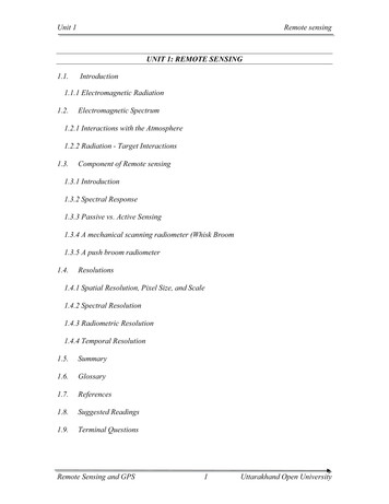
August 2008Making ElectricalConnectionsBefore taking measurements with the PT878, you must make all thenecessary electrical connections to the unit. This includes: power (required) transducers (required) Input/Output (optional) infrared interface (optional)All electrical connections are made to the top of the PT878 as shownin Figure 1-1 below.Input/OutputUpstream TransducerDownstream TransducerPowerInfrared TransceiverFigure 1-1: Electrical Connection Locations!WARNING!To ensure the safe operation of the PT878, you mustinstall and operate it as described in this manual. Inaddition, be sure to follow all applicable safety codesand regulations for installing electrical equipment inyour area. The PT878 and its transducers are designedfor use in general-purpose locations only.1-2Installation & Operation
August 2008Power ConnectionThe PT878 may be powered by either of the following: a 100-120/200-260 VAC wall-mount plug-in module 5 internal Cs-size NiCad high-energy rechargeable batteries a pack of 3.0 Ahr NiMH batteriesNote: An optional power supplement, part #703-1283, uses 6 AAalkaline batteries.Regardless of which power option is chosen, you must connect thepower cord as shown in Figure 1-1 on the previous page.IMPORTANT: When you receive the PT878, the batteries are notcharged. Therefore, to take measurements on batterypower, you must first charge the batteries as describedon page 1-5.Transducer ConnectionsThe transducer cables connect to the PT878 with LEMO coaxialtype connectors. Each color-coded cable should have a collar labeledUPSTREAM or DOWNSTREAM. Make transducer cableconnections to the top of the flowmeter as shown in Figure 1-1 on theprevious page. Because there are various types of transducers andinstallations, detailed transducer installation is discussed separately inthe Liquid Transducer Installation Guide (916-055).Input/Output ConnectionsThe PT878 provides one 0/4-20 mA current output and two 4-20 mAanalog inputs with switchable 16V supply for loop- poweredtemperature transmitters. It also supports digital, frequency, andtotalizer outputs. Connect the inputs/outputs using a LEMO multi-pin connector as shown in Figure 1-1 on the previous page. Thepin numbers for the connector and the color code for the standardinput/output cable are shown in Table 1-1 on the next page.Installation & Operation1-3
August 2008Input/Output Connections(cont.)Table 1-1: Cable Assembly for Analog Inputs/OutputsPin #Wire ColorDescription1BlackAnalog Out 12Red3WhiteTemperature Transmitter Supply orReturn (Input A)4YellowTemperature Transmitter Supply orReturn (Input B)5GreenAnalog Ground6OrangeDigital Output (frequency output,pulse totalizer, diagnostic output orcalibration gate)7BlueDigital Ground8VioletReceive Monitor16 V (switched)The Infrared InterfaceThe PT878 comes equipped with an internal infrared transceiver(shown in Figure 1-1 on page 1-2) that enables communicationbetween the meter and other IR devices, particularly the IR ports ordongles (IR to RS232 adapters) of Windows -based PCs. Users cansend and receive site and log data; they can also program the metervia the optional PanaView software interface. The PT878 wasdesigned for use with products that comply with the IrDA protocol.Caring for the PT878BatteriesThe PT878 is equipped with built-in rechargeable batteries to supportportable operation. To maintain optimum performance, these batteriesrequire a minimum of maintenance.Charging the BatteriesWhen you receive the PT878 or if the batteries have not been used fora long period of time, you must charge the batteries before operation.To fully charge the batteries, eight hours is required. When fullycharged, the batteries provide 8 to 10 hours of continuous operation.An internal battery gauge indicates the remaining power in thebatteries.1-4Installation & Operation
August 2008Charging the Batteries(cont.)IMPORTANT: To ensure the maximum charge, charge the batteries inan ambient temperature of 50 to 104 F (10 to 40 C).To charge the batteries, simply plug the AC power module cord intothe power jack (shown in Figure 1-1 on page 1-2) and be sure thebattery pack is installed. When the PT878 is plugged into line voltage,the internal battery charger automatically charges the batteries,whether the PT878 is ON or OFF. If the PT878 is ON, the Batteryicon in the upper right corner of the screen indicates battery status (asshown in Table 1-2 below).Note: For version 1B of the PT878 software, you must also pressthe red power key in the upper right corner of the keypad.IconTable 1-2: Battery Status IconsBattery StatusFull batteryPartially full batteryEmpty batteryFully charged battery, connected to AC powerCharging batteryDischarging batteryFailure/missing batteryNotification to check batteryStoring the BatteriesInstallation & OperationAlways observe the following battery storage temperature ranges: 2 days or less: -40 to 158 F (-40 to 70 C) less than 1 month: -4 to 131 F (-20 to 55 C) more than 1 month: 32 to 104 F (0 to 40 C)1-5
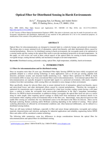
August 2008Replacing the Batteries!WARNING!Replace batteries only with the specified rechargeablebatteries. The battery charges even when the unit is OFF.Do not attempt to recharge non-rechargeable batteries.If you need to replace the rechargeable batteries, use therecommended 3.0 Ahr NiMH batteries (part number 200-081). Toreplace the batteries:1. Remove the rubber boot.2. Open the panel located on the back of the PT878 unit.3. Disconnect the old batteries and dispose of them properly.4. Install the new batteries (see Figure 1-2 below).Battery LocatedBehind PanelFigure 1-2: Back Panel of PT878Note: To further extend the battery power of the PT878, the GESensing Part #705-1283 option uses 6 AA alkaline batteries.1-6Installation & Operation
August 2008Powering ON and OFFCaution!For CE compliance, the PT878 is classified as a batterypowered device, not to be used with the AC adapter. Tocomply with CE certification, do not operate the meterwith the charger plugged in.To power the PT878 ON, press the red button in the upper-right-handcorner of the keypad. Immediately upon power up, the PT878 emits ashort beep and displays a “PCI Loader” message. It then validatesthe instrument programming, displays the GE Sensing logo and thesoftware version, and emits a long beep. If the meter fails any of thesetests, contact GE Sensing.!WARNING!If the meter fails the backup battery test, you must sendthe unit back to the factory for a battery replacement.After the meter conducts all the self checks, a screen similar to Figure1-3 below appears.ABC.SIT2000/11/30Velocity, ft/s0.00Delta-T, ns0.1009:53 AMSignal, dB32Volume, l/s0.0E0: No ErrorsFigure 1-3: Screen After Powering ONInstallation & Operation1-7
August 2008Powering ON and OFF(cont.)To turn the PT878 OFF, press the red key and hold it for 3 seconds.The screen now appears similar to Figure 1-4 below.Velocity, ft/sSignal, dBDelta-T, nsVolume, l/sSHUTDOWN: Meter OFFSLEEP: Meter IdleCANCEL: Resume OperationsShutdownSleepResumeFigure 1-4: The Shutdown MenuThree options are now available: Press [F1] to shut down the PT878 - This turns it completely OFF. Press [F2] to send the PT878 into sleep mode - In this mode, thePT878 remains in a standby mode and you can resume takingmeasurements immediately by pressing the power button again. Press [F3] to cancel the command - This returns the PT878 tonormal operation.Note: If the PT878 locks up, you can reset it by pressing the powerkey (the red key in the upper right corner) and holding it for15 seconds.1-8Installation & Operation
August 2008Using the Screen andKeypadThe essential features for operating the PT878 are the screen andkeypad. Although these features are common on portable instruments,the PT878 design offers special features to simplify and speed theoperation.The ScreenThe primary function of the screen is to display information in orderfor you to accurately and easily take measurements. The PT878screen consists of seven parts (see Figure 1-5 below).Status Bar(alternates withMenu ty, ft/s0.00Delta-T, ns0.10BatteryStatus09:53 AMSignal, dB32Volume, l/s0.0E0: No ErrorsError MessagesSystemTrayFunction KeysFigure 1-5: The PT878 Screen in Operate ModeThe top line of the screen is the status bar, which normally displaysthe time and date. However, when you press [MENU] (the menu key),the Menu Bar replaces the status bar.The middle of the screen is the work area, which displays themeasured parameters, numeric measurements, and both bar and linegraphs. However, when you enter a selection on the Menu Bar, thisarea displays menu prompts instead. Also, a line at the bottom of thework area also displays error code messages.Installation & Operation1-9
August 2008The Screen (cont.)The system tray displays icons that indicate meter operations nototherwise shown. Table 1-3 below lists the icons and their meanings.IconTable 1-3: Icons in the System TrayFunctionMeaningIR TransferIR data transfer in progress.AlertIndicates the meter encountered anerror in operation.LogIndicates a log is pending (nomarks) or running (marks).Heating/coolingIndicates heating or cooling energymode.StopwatchCalibration Gate Operation: Watchis stopped when the gate is closed,or runs when it is open.Snapshot(To file)Indicates that the Snapshot functionhas been activated, so users cantake screen captures.(To Printer)The bottom of the screen displays the three function key options:[F1], [F2] and [F3]. These keys have different functions, depending onthe task you are performing.1-10Installation & Operation
August 2008The KeypadThe PT878 keypad has 25 keys. The functions for each key aredescribed on the following page (see Figure 1-6 below):Figure 1-6: The PT878 KeypadInstallation & Operation1-11
August 2008The Keypad (cont.) 3 function keys ([F1], [F2], [F3]) — enable you to select the specialfunctions which appear at the bottom of the screen. 12 numeric keys (including [-] and [.]) — enable you to enternumeric data. 4 arrow keys ([W], [X], [S], [T]) — enable you to move throughthe menu options. [?] Help key— enables you to access on-line help. [MENU] Menu key — enables you to access the Main Menu. [ENTER] — enables you to enter a particular menu, and entersselected values into the PT878 memory. [SEL] — enables you to move between data measurements on thescreen. [ESC] — enables you to exit menus or menu options at any time;cancels a numeric entry. Red key [] — turns the power ON or OFF, and toggles thebacklight ON or OFF.1-12Installation & Operation
Chapter 2
Initial SetupIntroduction. . . . . . . . . . . . . . . . . . . . . . . . . . . . . . . . . . . . . . . . . . . . . . . . . . . . 2-1Entering the Program Menu . . . . . . . . . . . . . . . . . . . . . . . . . . . . . . . . . . . . . 2-1Entering the Transducer Parameters . . . . . . . . . . . . . . . . . . . . . . . . . . . . . 2-2Entering the Pipe Parameters . . . . . . . . . . . . . . . . . . . . . . . . . . . . . . . . . . . . 2-4Entering the Pipe Lining Parameters . . . . . . . . . . . . . . . . . . . . . . . . . . . . . . 2-6Entering the Fluid Parameters . . . . . . . . . . . . . . . . . . . . . . . . . . . . . . . . . . . 2-7Entering the Signal Path Parameters . . . . . . . . . . . . . . . . . . . . . . . . . . . . . 2-8Entering Correction Factors . . . . . . . . . . . . . . . . . . . . . . . . . . . . . . . . . . . . 2-10
August 2008IntroductionThe PT878 Program Menu enables you to program the parametersthat define an installation site. As a minimum, the transducer, pipeand fluid data must be entered into the meter before measurementscan be taken. The programmed data can then be saved as a site file,and the PT878 can store up to 1 MB (or 32 site files) of data.IMPORTANT: For menu options not discussed in this abridgedmanual or if you see an error or warning screen whileprogramming your meter, refer to your full User’sManual (910-219) for further instructions.Entering the ProgramMenuTo enter the Program Menu, press the [MENU] key at the lower right ofthe PT878 keypad. The Menu Bar replaces the Status Bar at the top ofthe screen. Press the [X] arrow key once to scroll to the ProgramMenu and press [ENTER] (see Figure 2-1 below).Note: As an aid in following the programming instructions in thismanual, refer to Appendix A, Menu Maps.Site Program Meter Logging .00Signal, dB32EnergyDelta-T,Analog nsInputAnalog OutputDigital OutputUser FunctionsCoCorrectionFactors0.10Volume, l/s0.0E0: No ErrorsFigure 2-1: The Program MenuUse the [T]and [S] arrow keys to scroll through the menu options.Then press [ENTER] to select that option.Initial Setup2-1
August 2008Entering the ProgramMenu (cont.)When entering information in an option window, press: the [T] key to scroll down the list the [S] key to scroll up the list the [F2] key (Cancel) or the [ESC] key to close a window at any timeand return to Operate Mode without changing the data.Note: If you enter an incorrect numeric value, press the [W] key toerase the last digit entered.Entering the TransducerParametersTo program the Transducer data, scroll to the Transducer option onthe Program Menu and press [ENTER] (see Figure 2-2 below).Note: Refer to your Transducer Installation Guide for additionalinformation about transducers and nSpecialMHzWedge Ang50 Wedge Tmp25Wedge SSCancel14 µsTw C1219.2 m/sOKFigure 2-2: The Transducer Option Window1. At the Type prompt, use the [W] and [X] keys to select the type oftransducer used in your installation (wetted or clamp-on). Press[ENTER] to confirm the choice.Note: Each choice made in the Transducer and Pipe menus willdetermine the additional options that must be programmed.2-2Initial Setup
August 2008Entering the TransducerParameters (cont.)2. Press the [T] key to reach the Transducer prompt and press[ENTER]. A drop-down list of transducer numbers for your chosentransducer type opens. Scroll to the number engraved on yourtransducer body, or scroll to Special if there is no transducernumber. Press [ENTER] to confirm your selection.Note: To speed scrolling, you can press the [X] key to scroll downby a page, or the [W] key to s
Installation & Operation 1-1 August 2008 Introduction The PT878 is a transit-time flowmeter that combines all the features of a full-size flowmeter with the advantages of a portable instrument: measure the flow rate of acoustically-conductive single-phase fluids measure flow velocities from 0.03 to 12 m/sec energy flow rate may be calculated for water, glycol, and water/