Transcription
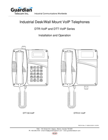
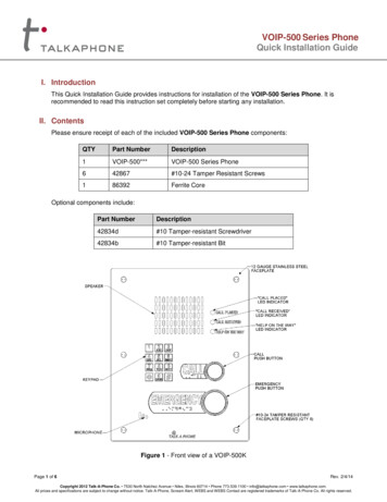
VOIP-500 Series PhoneQuick Installation GuideI. IntroductionThis Quick Installation Guide provides instructions for installation of the VOIP-500 Series Phone. It isrecommended to read this instruction set completely before starting any installation.II. ContentsPlease ensure receipt of each of the included VOIP-500 Series Phone components:QTYPart NumberDescription1VOIP-500***VOIP-500 Series Phone642867#10-24 Tamper Resistant Screws186392Ferrite CoreOptional components include:Part NumberDescription42834d#10 Tamper-resistant Screwdriver42834b#10 Tamper-resistant BitFigure 1 - Front view of a VOIP-500KPage 1 of 6Rev. 2/4/14Copyright 2012 Talk-A-Phone Co. 7530 North Natchez Avenue Niles, Illinois 60714 Phone 773.539.1100 info@talkaphone.com www.talkaphone.com.All prices and specifications are subject to change without notice. Talk-A-Phone, Scream Alert, WEBS and WEBS Contact are registered trademarks of Talk-A-Phone Co. All rights reserved.
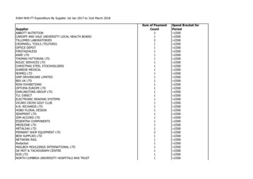
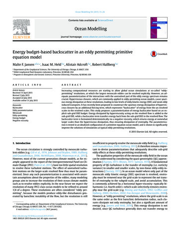
VOIP-500 Series PhoneQuick Installation GuideIII. Field Wiring Installation1. Remove and set aside the VOIP-500 Series Phone assembly.2. Remove the back box from the VOIP-500 Series Phone assembly by unfastening the six (6), #632 nuts and washers.3. For PCB (Printed Circuit Board) wiring details, refer to Figure 2.Figure 2 - Internal PCB (Printed Circuit Board) viewIV. Network ConnectivityThe VOIP-500 Series Phone is equipped with two (2) Ethernet ports. The WAN Ethernet (PoE) portshould be used as the primary port for data communications. The WAN Ethernet port can be used topower the phone via an IEEE 802.3af, Class 3 compliant PoE supply.The VOIP-500 Series Phone has a layer 2 switchport labeled LAN Ethernet which can provide networkconnectivity to an auxiliary device e.g. (IP Camera, Card Reader, etc). The LAN Ethernet port is a passthrough port and cannot be used to access the phone.When installing the Network cable, it is essential to have a ferrite core (provided with the phone),installed on to the cable as close as possible to the connector. Make sure the network cable is passedtwice through the ferrite core, forming a loop of not less than one (1) inch in diameter.A cable with a rating of Cat5e or higher with an RJ45 connector is typical for all network cables.Page 2 of 6Rev. 2/4/14Copyright 2012 Talk-A-Phone Co. 7530 North Natchez Avenue Niles, Illinois 60714 Phone 773.539.1100 info@talkaphone.com www.talkaphone.com.All prices and specifications are subject to change without notice. Talk-A-Phone, Scream Alert, WEBS and WEBS Contact are registered trademarks of Talk-A-Phone Co. All rights reserved.
VOIP-500 Series PhoneQuick Installation GuideFigure 3 - Installation of the ferrite core on the network cableV. Power RequirementsThe VOIP-500 Series Phone can be powered over Ethernet or through a dedicated, line-regulatedpower supply that meets the following specifications:Power InputDescriptionAcceptable VoltagePower ConsumptionEthernet WANPoE – IEEE 802.3af Class 3 36-57 VDC150 mAPower Supply Input12 VDC 10-14 VDC500-800 mAPower Supply Input24 VDC 21-27 VDC300-500 mAPower Supply Input24 VAC 21-27 VAC300-500 mAPage 3 of 6Rev. 2/4/14Copyright 2012 Talk-A-Phone Co. 7530 North Natchez Avenue Niles, Illinois 60714 Phone 773.539.1100 info@talkaphone.com www.talkaphone.com.All prices and specifications are subject to change without notice. Talk-A-Phone, Scream Alert, WEBS and WEBS Contact are registered trademarks of Talk-A-Phone Co. All rights reserved.
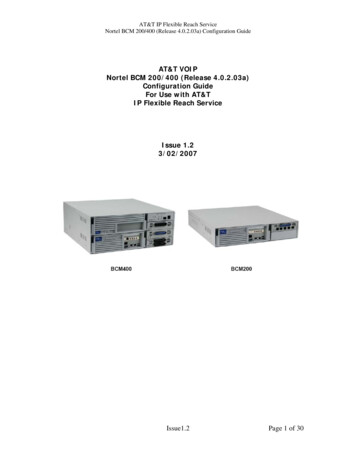
VOIP-500 Series PhoneQuick Installation GuideVI. Power InstallationPower over Ethernet: Connect the Ethernet cable (Power Data) to the WAN Ethernet port on thePCB as shown in Figure 2.Local Power:For 12 VDC power mode place the internal jumpers on the two outermostterminals as shown in Figure 4. Once the jumpers are correctly set, connect thepower supply to the Power Supply Input using a two conductor, No. 24 to 12AWG cable as shown in Figure 5. For 12 VDC, ensure the Negative supply isconnected to terminal A, and the Positive supply is connected to terminal B.For 24 VDC/VAC power modes, place the internal jumper on the two innermostterminals as shown in Figure 4. Once the jumpers are correctly set, connect thepower supply to the Power Supply Input using a two conductor, No. 24 to 12AWG cable as shown in Figure 5. For 24 VDC/VAC, ensure the Positive supplyis connected to terminal A, and the Negative supply is connected to terminal B.Figure 4 - Internal Jumper position for external power modes.Phone default setting is 24 VDC/VAC.Figure 5 – Power Supply Input connection polarityPage 4 of 6Rev. 2/4/14Copyright 2012 Talk-A-Phone Co. 7530 North Natchez Avenue Niles, Illinois 60714 Phone 773.539.1100 info@talkaphone.com www.talkaphone.com.All prices and specifications are subject to change without notice. Talk-A-Phone, Scream Alert, WEBS and WEBS Contact are registered trademarks of Talk-A-Phone Co. All rights reserved.
VOIP-500 Series PhoneQuick Installation GuideVII. Earth GroundThe faceplate of the phone must be connected to earth ground. Install a #10 ring terminal to the groundwire before connecting it to the earth ground terminal on the rear of the faceplate as shown in Figure 2.VIII. Auxiliary Input / Output1. The VOIP-500 Series Phone has three (3) Auxiliary Inputs (dry contact, 10 mA @ 8 VDC) andthree (3) Auxiliary Outputs (dry contact, 120 mA @ 120 VAC/DC). Auxiliary Outputs allowperipheral equipment such as strobe lights, PTZ cameras, door entry systems, etc. to beactivated when the push button is pressed.2. Two (2) removable 6-pin connector plugs are provided for the auxiliary input and output as shownin the Figure 6.3. The Auxiliary Input and Auxiliary Output connections are as follows:Auxiliary Input ConnectionConnector Plug Pin PositionAux. Input 1Position 7 and 8Aux. Input 2Position 9 and 10Aux. Input 3Position 11 and 12Auxiliary Output ConnectionConnector Plug Pin PositionAux. Output 1Position 1 and 2Aux. Output 2Position 3 and 4Aux. Output 3Position 5 and 6Use a two conductor, No. 28 to 16 AWG cable size for all auxiliary connections.Figure 6 - Auxiliary Input/Output and Power connectorsPage 5 of 6Rev. 2/4/14Copyright 2012 Talk-A-Phone Co. 7530 North Natchez Avenue Niles, Illinois 60714 Phone 773.539.1100 info@talkaphone.com www.talkaphone.com.All prices and specifications are subject to change without notice. Talk-A-Phone, Scream Alert, WEBS and WEBS Contact are registered trademarks of Talk-A-Phone Co. All rights reserved.
VOIP-500 Series PhoneQuick Installation GuideX. Line Level AudioConnect the Line Level Audio connector on the PCB as shown in the Figure 2, to the respective device on the other end, such as the WEBS paging amplifier, recording device, speaker, etc.XI. Final AssemblyAfter completing the field wiring installation, fasten the back box on to the faceplate with the six (6)hardware nuts and washers.NOTE: It is the installer’s obligation to ensure that the wiring should pass through the cable entry holeat the bottom of the back box. Please exercise caution when reinstalling the back box and ensure thatno cables are crushed during the process.Install the VOIP-500 Series Phone into its appropriate mount (e.g. ETP-SM, as shown in Figure 7),with the six (6) tamper resistant #10 faceplate screws provided.Figure 7 - Installation of VOIP-500K into an ETP-SMPage 6 of 6Rev. 2/4/14Copyright 2012 Talk-A-Phone Co. 7530 North Natchez Avenue Niles, Illinois 60714 Phone 773.539.1100 info@talkaphone.com www.talkaphone.com.All prices and specifications are subject to change without notice. Talk-A-Phone, Scream Alert, WEBS and WEBS Contact are registered trademarks of Talk-A-Phone Co. All rights reserved.
This Quick Installation Guide provides instructions for installation of the VOIP-500 Series Phone. It is recommended to read this instruction set completely before starting any installation. II. Contents Please ensure receipt of each of the included VOIP-500 Series Phone components: QTY Part Number Description 1 VOIP-500*** VOIP-500 Series Phone