Transcription
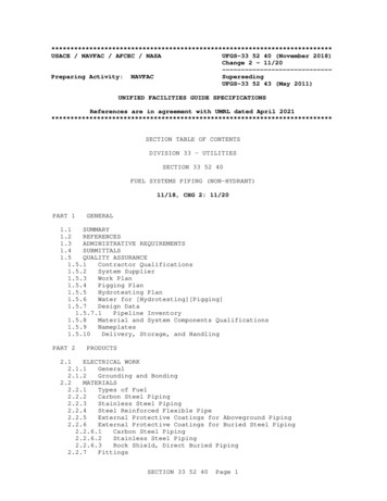
************************USACE / NAVFAC / AFCEC / NASAUFGS-33 52 40 (November 2018)Change 2 - 11/20----------------------------Preparing Activity: NAVFACSupersedingUFGS-33 52 43 (May 2011)UNIFIED FACILITIES GUIDE SPECIFICATIONSReferences are in agreement with UMRL dated April ****************************SECTION TABLE OF CONTENTSDIVISION 33 - UTILITIESSECTION 33 52 40FUEL SYSTEMS PIPING (NON-HYDRANT)11/18, CHG 2: 11/20PART 1GENERAL1.1SUMMARY1.2REFERENCES1.3ADMINISTRATIVE REQUIREMENTS1.4SUBMITTALS1.5QUALITY ASSURANCE1.5.1Contractor Qualifications1.5.2System Supplier1.5.3Work Plan1.5.4Pigging Plan1.5.5Hydrotesting Plan1.5.6Water for [Hydrotesting][Pigging]1.5.7Design Data1.5.7.1Pipeline Inventory1.5.8Material and System Components Qualifications1.5.9Nameplates1.5.10Delivery, Storage, and HandlingPART 2PRODUCTS2.1ELECTRICAL WORK2.1.1General2.1.2Grounding and Bonding2.2MATERIALS2.2.1Types of Fuel2.2.2Carbon Steel Piping2.2.3Stainless Steel Piping2.2.4Steel Reinforced Flexible Pipe2.2.5External Protective Coatings for Aboveground Piping2.2.6External Protective Coatings for Buried Steel Piping2.2.6.1Carbon Steel Piping2.2.6.2Stainless Steel Piping2.2.6.3Rock Shield, Direct Buried Piping2.2.7FittingsSECTION 33 52 40Page 1
2.2.7.1General2.2.7.2Carbon Steel Fittings2.2.7.3Stainless Steel Fittings2.2.7.4Steel Reinforced Flexible Pipe Fittings2.2.8Insulating Flange Kits (Electrically Isolating)2.2.9Bolts, Nuts and Washers2.2.10Flange Gaskets, Non-Metallic, Non-Electrically Isolating2.2.10.1Nitrile Butadiene (Buna-N)2.2.10.2Acrylonitrile Butadiene Rubber (NBR)2.2.10.3Polytetrafluoroethylene (PTFE)2.2.10.4Fluoro Rubber FKM2.2.10.5Fluoroelastomer FPM2.2.11Flange Gaskets, Metallic2.2.12Flange Protectors2.3MANUAL VALVES2.3.1Ball Valves2.3.1.1Materials2.3.1.2V-Port Ball Valve2.3.1.3Full Port Ball (DBBV) Valves for Piggable Lines2.3.1.4Electric Valve Actuator2.3.2Plug (Double Block and Bleed) Valves2.3.2.1General2.3.2.2Valve Operation2.3.2.3Relief Valves2.3.2.4Bleed Valves2.3.2.5Electric Valve Actuator2.3.3Swing Check Valves2.3.4Silent Check Valves2.3.5Butterfly Valve with Fusible Link Operator2.3.6Globe Valve2.4THERMAL RELIEF VALVE2.4.1Valve Material2.4.2Thermal Relief Valve (ASME Type)2.4.3Thermal Relief Valve (Balanced Type)2.5PIPING ACCESSORIES2.5.1Flexible Ball Joints2.5.2Bellows Expansion Joints for Axial Movement2.5.3Mechanically Adjustable Segmented Elastomeric Seal2.5.4Pipe Sleeves2.5.5Strainers2.5.5.1Basket Type2.5.5.2Cone Type2.5.6Thermometer2.5.7Pressure Gauge2.5.8Pipe Supports2.5.8.1General2.5.8.2Adjustable Pipe Supports2.5.8.3Low Friction Supports2.5.8.4U-bolt Half Round Supports2.5.8.5Concrete and Grout2.5.9Sample Connections2.5.10Sight Flow Indicators2.6PIGGING SYSTEM COMPONENTS2.6.1Maintenance Pig Launchers and Receivers2.6.2Smart Pig Launchers and Receivers2.6.3Launcher and Receiver Closure Door2.6.4Signaler2.7FLEXIBLE HOSE CONNECTORS2.8AUTOMATIC AIR VENTSECTION 33 52 40Page 2
2.9SURGE SUPPRESSOR TANK AND VALVE2.10MISCELLANEOUS ACCESSORIES2.10.1Concrete Anchor Bolts2.10.2Coatings for Bolts, Studs, Nuts, and Washers2.10.3Polytetrafluoroethylene (PTFE) Tape2.10.4Pipe Sleeves2.10.5Escutcheon2.10.6Pipe Casings2.10.7Buried Utility Tape2.10.8Pipeline Markers2.11FINISHES2.11.1Factory Coating2.11.1.1Valves2.11.1.2Equipment and Components2.11.2Field PaintingPART 3EXECUTION3.1GENERAL3.2VERIFICATION OF DIMENSIONS3.3CLEANING OF PIPING3.4TRENCHING AND BACKFILLING3.5PIPING LAYOUT REQUIREMENTS3.5.1Pipe Fabrication3.5.2Interferences and Measurements3.5.3Space and Access3.5.4Location3.5.5Pipe Supports3.5.6Structural Support3.5.7Grade3.5.8Size Changes3.5.9Direction Changes3.5.10Threaded End Connections3.5.11Existing Pipe Systems3.5.12Bolted Connections3.5.13Flanges and Unions3.5.14Flange Protector3.5.15Manual Valves3.5.16Air Vents3.5.17Drains3.5.18Bellows Expansion Joints3.5.19Thermometers3.5.20Pipe Sleeves3.5.21Escutcheons3.6SEISMIC REQUIREMENTS3.7STRUCTURAL 9.1Precautions3.9.2Protective Coatings for Buried Piping Including StainlessSteel Piping3.9.2.1Application of Coating System3.9.2.2Inspection and Testing3.9.2.3Damage Repair3.10INTERIOR EPOXY COATING3.11INSTALLATION OF UNDERGROUND PIPE3.11.1Pipe Assembly3.11.2Warning Tapes in Earth TrenchesSECTION 33 52 40Page 3
3.11.3Clearances3.11.4Protective Coating3.11.5Pipe Casing3.11.6Pipeline Markers3.11.7Steel Reinforced Flexible Pipe3.12SYSTEM COMMISSIONING3.13TESTING3.13.1Before Backfilling3.13.1.1Exterior Coating Holiday Test3.13.2Pneumatic Test3.13.2.1Pneumatic Test Procedure3.13.3Hydrostatic Test3.13.4Soak Testing3.13.5Performance Testing3.14PIPE PIGGING - CLEANING3.14.1General3.14.2Use of Fuel in Cleaning Pigging3.14.3Use of Water in Cleaning Pigging3.14.4Cleaning Pig Run3.14.5Wire Brush Pig Run3.15PIPE PIGGING VERIFICATION3.15.1Use of Water in Pipe Pigging Verification3.15.2Geometry/Ultrasonic Tool Reports3.15.3Pipeline Internal Inspection Operations3.15.3.1General3.15.3.2Preparatory Work3.15.3.3Pig Load And Launch3.15.3.4Pipeline Operation During Pigging3.15.3.5Brush and Gauging Survey3.15.3.6Geometry/Ultrasonic Survey3.15.3.7Pipe Wall Thickness Survey3.15.3.8Lost Pig3.16DEMONSTRATIONS3.17POSTED OPERATING INSTRUCTIONS-- End of Section Table of Contents --SECTION 33 52 40Page 4
************************USACE / NAVFAC / AFCEC / NASAUFGS-33 52 40 (November 2018)Change 2 - 11/20----------------------------Preparing Activity: NAVFACSupersedingUFGS-33 52 43 (May 2011)UNIFIED FACILITIES GUIDE SPECIFICATIONSReferences are in agreement with UMRL dated April ****************************SECTION 33 52 40FUEL SYSTEMS PIPING (NON-HYDRANT)11/18, CHG 2: *****************************NOTE: This guide specification covers therequirements for piping, piping components, valvingand miscellaneous accessories for general fuelingsystems, non-hydrant type and non-service station.Do not use this specification for designs related topressurized hydrant fueling systems and superrefueler fillstands. For such systems, refer to therequirements of the DOD Type III/IV/V, and Cut andcover Hydrant Refueling System Standards.Adhere to UFC 1-300-02 Unified Facilities GuideSpecifications (UFGS) Format Standard when editingthis guide specification or preparing new projectspecification sections. Edit this guidespecification for project specific requirements byadding, deleting, or revising text. For bracketeditems, choose applicable item(s) or insertappropriate information.Remove information and requirements not required inrespective project, whether or not brackets arepresent.Comments, suggestions and recommended changes forthis guide specification are welcome and should besubmitted as a Criteria Change Request ******************************PART ********************************NOTE: Use this UFGS in conjunction with UFC3-460-01 "Design: Petroleum Fuel Facilities".Include in this specification any additionalequipment/devices necessary to meet state and localregulations.The specification is written around ASME's standardClass 150 rating. For applications requiring higherpressure ratings (e.g., Class 300), the designerSECTION 33 52 40Page 5
will have to modify this specification appropriately.Cut and Cover systems must conform to StandardDesign AW 078-24-33 UNDERGROUND VERTICAL STORAGETANKS CUT AND COVER. Field fabricated ASTs mustconform to AW 078-24-27 ABOVEGROUND VERTICAL STEELTANKS WITH FIXED ROOFS. Standards can be found onthe Whole Building Design Guide at the is section defines the requirements for pipe, piping components, andvalves as related to an non-hydrant, non-service station, fueldistribution system. Such systems include, but are not limited to: marinereceipt, pipeline receipt, truck off-loading receipt, pump house, pumppad, truck loading, marine loading, transfer pipeline, product recovery,and other miscellaneous piping systems. Provide the entire fueldistribution system as a complete and fully operational system. Size,select, construct, and install equipment and system components to operatetogether as a complete system. Substitutions of functions specifiedherein will not be acceptable. Coordinate the work of the systemmanufacturer's service personnel during construction, testing,calibration, and acceptance of the system. System components and pipingspecified herein must be designed to handle a working pressure of [1900][ ] kPa [275] [ ] psig at 38 deg C 100 deg F. Componentsspecified herein must be compatible with the fuel to be handled.Components to be suitable for outside, unsheltered location, and tofunction normally in ambient temperatures between [ ] degrees Cdegrees F and [ ] degrees C degrees ***************************************NOTE: This paragraph is used to list thepublications cited in the text of the guidespecification. The publications are referred to inthe text by basic designation only and listed inthis paragraph by organization, designation, date,and title.Use the Reference Wizard's Check Reference featurewhen you add a Reference Identifier (RID) outside ofthe Section's Reference Article to automaticallyplace the reference in the Reference Article. Alsouse the Reference Wizard's Check Reference featureto update the issue dates.References not used in the text will automaticallybe deleted from this section of the projectspecification when you choose to reconcilereferences in the publish print ********************************The publications listed below form a part of this specification to theextent referenced. The publications are referred to within the text bythe basic designation only.SECTION 33 52 40Page 6
AMERICAN PETROLEUM INSTITUTE (API)API 570(2016; Addendum 1 2017; Addendum 2 2018;ERTA 1 2018) Piping Inspection Code:In-Service Inspection, Rating, Repair, andAlteration of Piping SystemsAPI RP 540(1999; R 2004) Electrical Installations inPetroleum Processing PlantsAPI RP 1110(2013; R 2018) Recommended Practice forthe Pressure Testing of Steel Pipelinesfor the Transportation of Gas, PetroleumGas, Hazardous Liquids, Highly VolatileLiquids, or Carbon DioxideAPI RP 1595(2012; R 2019; 2nd Ed) Design,Construction, Operation, Maintenance, andInspection of Aviation Pre-AirfieldStorage TerminalsAPI RP 2003(2015; 8th Ed) Protection AgainstIgnitions Arising out of Static,Lightning, and Stray CurrentsAPI RP 2009(2002; R 2007; 7th Ed) Safe Welding,Cutting, and Hot Work Practices inRefineries, Gasoline Plants, andPetrochemical PlantsAPI RP 2200(1999; R 2004) Electrical Installations inPetroleum Processing PlantsAPI STD 600(2015) Steel Gate Valves-Flanged andButt-welding Ends, Bolted BonnetsAPI STD 608(2012) Metal Ball Valves - Flanged,Threaded, And Welding EndAPI Spec 5L(2018; 46th Ed; ERTA 2018) Line PipeAPI Spec 6D(June 2018, 4th Ed; Errata 1 July 2018;Errata 2 August 2018) Specification forPipeline and Piping ValvesAPI Spec 6FA(1999; R 2006; Errata 2006; Errata 2008; R2011) Specification for Fire Test forValvesAPI Spec 17J(2016; Errata 2 2017; ADD 1 2017)Specification for Unbonded Flexible PipeAPI Std 594(2017) Check Valves:and Butt-WeldingAPI Std 607(2016) Fire Test for Quarter-turn Valvesand Valves Equipped with Non-metallic SeatsSECTION 33 52 40Page 7Flanged, Lug, Wafer
API Std 609(2016; ERTA 2017) Butterfly Valves:Double Flanged, Lug-and-Wafer TypeAMERICAN SOCIETY OF MECHANICAL ENGINEERS (ASME)ASME B1.1(2003; R 2018) Unified Inch Screw Threads(UN and UNR Thread Form)ASME B16.5(2020) Pipe Flanges and Flanged FittingsNPS 1/2 Through NPS 24 Metric/Inch StandardASME B16.9(2018) Factory-Made Wrought ButtweldingFittingsASME B16.11(2016) Forged Fittings, Socket-Welding andThreadedASME B16.20(2017) Metallic Gaskets for Pipe FlangesASME B16.21(2016) Nonmetallic Flat Gaskets for PipeFlangesASME B16.34(2021) Valves - Flanged, Threaded andWelding EndASME B18.2.1(2012; Errata 2013) Square and Hex Boltsand Screws (Inch Series)ASME B18.2.2(2015) Nuts for General Applications:Machine Screw Nuts, Hex, Square, HexFlange, and Coupling Nuts (Inch Series)ASME B31.3(2016) Process PipingASME BPVC SEC VIII D1(2019) BPVC Section VIII-Rules forConstruction of Pressure Vessels Division 1AMERICAN WATER WORKS ASSOCIATION (AWWA)AWWA C210(2015) Standard for Liquid Epoxy CoatingSystems for the Interior and Exterior ofSteel Water PipelinesASTM INTERNATIONAL (ASTM)ASTM A36/A36M(2019) Standard Specification for CarbonStructural SteelASTM A53/A53M(2020) Standard Specification for Pipe,Steel, Black and Hot-Dipped, Zinc-Coated,Welded and SeamlessASTM A105/A105M(2021) Standard Specification for CarbonSteel Forgings for Piping ApplicationsASTM A123/A123M(2017) Standard Specification for Zinc(Hot-Dip Galvanized) Coatings on Iron andSteel ProductsSECTION 33 52 40Page 8
ASTM A153/A153M(2016a) Standard Specification for ZincCoating (Hot-Dip) on Iron and SteelHardwareASTM A182/A182M(2020) Standard Specification for Forgedor Rolled Alloy and Stainless Steel PipeFlanges, Forged Fittings, and Valves andParts for High-Temperature ServiceASTM A193/A193M(2020) Standard Specification forAlloy-Steel and Stainless Steel BoltingMaterials for High-Temperature Service andOther Special Purpose ApplicationsASTM A194/A194M(2020a) Standard Specification for CarbonSteel, Alloy Steel, and Stainless SteelNuts for Bolts for High-Pressure orHigh-Temperature Service, or BothASTM A234/A234M(2019) Standard Specification for PipingFittings of Wrought Carbon Steel and AlloySteel for Mode
API RP 2009 (2002; R 2007; 7th Ed) Safe Welding, Cutting, and Hot Work Practices in Refineries, Gasoline Plants, and Petrochemical Plants API RP 2200 (1999; R 2004) Electrical Installations in Petroleum Processing Plants API STD 600 (2015) Steel Gate Valves-Flanged and Butt-welding Ends, Bolted Bonnets API STD 608 (2012) Metal Ball Valves - Flanged, Threaded, And Welding End API