Transcription
SD12 Operation ManualUser Manual - Getting StartedTo be read in conjunction with the SD Series Software ReferenceUser Manual Version A for Software Versions 9.0.900 0-1
SD12 Operation Manual0-2
SD12 Operation ManualCopyright 2016 Digico UK LtdAll rights reserved.No part of this publication may be reproduced, transmitted, transcribed, stored in a retrieval system, or translated into any language inany form by any means without the written permission of Digico UK Ltd. Information in this manual is subject to change without notice,and does not represent a commitment on the part of the vendor. Digico UK Ltd shall not be liable for any loss or damage whatsoeverarising from the use of information or any error contained in this manual.All repair and service of the SD12 product should be undertaken by Digico UK Ltd or its authorised agents. Digico UK Ltd cannot acceptany liability whatsoever for any loss or damage caused by service, maintenance, or repair by unauthorised personnel.Software License NoticeYour license agreement with Digico UK Ltd, which is included with the SD12 product, specifies the permitted and prohibited uses of theproduct. Any unauthorised duplication or use of Digico UK Ltd software, in whole or in part, in print or in any other storage and retrievalsystem is prohibited.Licenses and TrademarksThe SD12 logo and SD12 name are trademarks, and Digico UK Ltd and the Digico UK Ltd logo are registered trademarks of Digico UKLtd. Microsoft is a registered trademark and Windows is a trademark of Microsoft Corp.Digico (UK) LtdUnit 10Silverglade Business ParkLeatherhead RoadChessingtonSurreyKT9 2QLEnglandTelephone: 44 (0)1372 845600Fax: 44 (0)1372 igico.bizManual Issue and Date: Issue A - December 2016 - For Version 9.0.900 SoftwareLicence Agreement"Product":SD12 software product produced by Digico UK Ltd intended for use on Target Platform identified below."Target Platform": Digico SD12 Digital Console system.In return for the payment of the one-time fee, the Customer (identified at the end of this Agreement) receives from Digico UK Ltd alicence to use the Product subject to the following terms and conditions.1. The Product may be used without time limit by the Customer on the Target Platform.2. The Customer must register the Product with Digico UK Ltd. Registering the Product is deemed an acceptance of the terms andconditions in this agreement.3. The Product and its licence are not transferable, and the Customer is not permitted to onward-license to any third party. The Customer indemnifies Digico UK Ltd against any and all claims and actions arising from third party use of copies of the Product made bythe Customer.4. The Customer agrees not to attempt to decompile the object code of the Product otherwise than in circumstances specifically provided for by law, and then only after consultation with Digico UK Ltd.5. The Customer agrees not to use, or licence the Product for use, with equipment other than the Target Platform.6. The Customer agrees not to modify the Product without the prior written consent of Digico UK Ltd.7. This Agreement applies to any enhancement or upgrades that may become available for the Product.8. This Agreement does not transfer any right, title, or interest in the Product to Customer except as specifically set forth herein.9. Digico UK Ltd reserves the right to terminate this Agreement upon breach, in which event Customer shall thereafter only be authorised to use the Product to the extent that its contractual commitments to third parties require and then only where such commitments relate to use of the Product as authorised in the foregoing provisions of the Agreement.LIMITED WARRANTY - Digico UK Ltd warrants for a period of 1 year from the date of purchase of the Product, the Product will reasonably execute its programming instructions when properly installed on the Target Platform. In the event that this Product fails to executeits programming instructions during the warranty period, the Customer's remedy shall be to return the Product to Digico UK Ltd forreplacement or repair at Digico UK Ltd option. Digico UK Ltd makes no other express warranty, whether written or oral with respect ofthis Product.LIMITATION OF LIABILITY - Except as otherwise expressly provided by law, (a) the remedies provided above are the Customer's soleand exclusive remedies and (b) Digico UK Ltd shall not be liable for any direct, indirect, special, incidental, or consequential damages(including lost profit whether based on warranty, contract, tort, or any other legal theory.)This agreement is made under the Laws of England.LICENCE NO:.REGISTRATION DATE:.0-3
SD12 Operation ManualContents1.1 The Console.61.2 Manual Overview.61.3 Before You Start.71.3.1 Worksurface Layout. .71.3.2 Layers and Banks. .91.3.3 Using the Control Surface. .101.3.4 The Assigned Channel. .101.3.5 The Master Faders. .131.3.6 Channel Types. .141.4 Hardware Configuration.151.4.1 Connections. .151.5 Software Configuration.161.5.1 Templates. .161.5.2 Session Structure Overview. .161.5.3 Audio I/O Overview. .171.5.4 Opto V220 (DiGiRacks) and Opto V221 (SD Racks). .181.5.5 Single SD Console System. .181.5.6 Automatic Conforming. .181.5.7 Manual Conforming of Racks. .191.5.8 Rack Sharing. .201.5.9 Assigning Faders to the Worksurface. .201.6 Saving and Loading Sessions.211.7 Audio Sync.221.8 Routing Basics.231.8.1 Selecting Inputs & Outputs. .231.8.2 Ripple Channels. .241.8.3 Channel Names. .241.9 Channel Processing.251.9.1 Dynamic EQ. .251.9.2 Dynamics. .261.9.3 Auxiliaries. .271.10 The Matrix.281.11 Control Groups.291.12 Multi-channel formats.300-4
SD12 Operation Manual1.13 Solo Setup.312.1 DMI Cards.292.1.2 Fitting DMI Cards. .292.2 MADI DMI Cards.302.2.1 Connecting MADI DMI. .302.2.2 Sharing Racks with MADI DMI. .332.3 DMI-DANTE Cards.352.4 DMI - ADC - DAC - AES Cards.362.5 DMI - Waves - Hydra Cards.370-5
SD12 - Getting Started1.1 The ConsoleThe Digico SD12 consists of a worksurface, an audio engine and a range of onboard inputs and outputs. This can be connected to multiple Input/Output Rack Units by optical fibre and/or MADI links, which carry all the audio input and output signals.It also provides two DMI slots for the fitting of optional I/O cards and a "UBMADI" port.NOTE: The UBMADI (USB AUDIO) port provides up to 48 I/O channels of audio when the console is running at 48kHzand 24 I/O channels when the console is running at 96kHz via a USB connection."UBMADI" runs at 48kHz irrespective of the console sample rateThe console worksurface consists of 2 sections that can be configured to control up to 72 input channels, 12 VCAs, 36 busses plus aMaster buss (Stereo or LCR) and a 12 x 8 Matrix.The left section has 12 assignable faders and a set of assignable on-screen channel controls, the right section has 12 assignable fadersand a pair of additional faders which are fully assignable but default to being Master Buss and Solo 1.The console's buss architecture is dynamic, and can support mono, stereo and LCR configurations.Multiple console setups can provide:Front of House and Monitoring with shared stage racks and gain tracking.Remote control of one console from another console or from a laptop computer.1.2 Manual OverviewThis manual provides an overview of the desk, and describes some of the basic operating principles which the user will need to understand in order to run the desk.For full details on all SD software functionality please refer to the SD Series Software Reference Manual available for download at www.digico.bizThe following typographical convention used in this manual: An arrow bracket ( ) is used to indicate a sequence of button pressing.For example, Layout Fader Banks indicates that the Fader Banks button is accessed by first pressing the Layout button.1-6
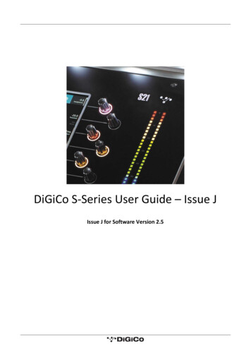
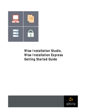
SD12 - Getting Started1.3 Before You StartThere are certain general operating principles and terms that should be understood before continuing to use this manual.Please read this chapter carefully before proceeding.1.3.1 Worksurface Layout.Left SectionALT Input SwitchHigh and Low Pass FiltersQuick Select4 Band Dynamic Parametric EQMultiband DynamicsThresholds & On / OffChannel Inserts A & B On/OffDirect Out On/OffHard Mute & Undo/RedoChannel Scroll2nd Function & Option/AllAssignable Rotaries and SwitchesAux / Pan / Dynamics/FX ControlsScreen ScrollMute and Interactive LCDFunction ButtonLayer SwitchChannel FadersChannel Fader BanksRight SectionUSB PortMacro ControlQuick SelectHeadphones & TalkbackSolosAssignable Rotaries and SwitchesAux / Pan / Dynamics/FX ControlsSnapshot ControlTouch/TurnMute and Channel Select ButtonsChannel FadersMaster Screen AssignAssignable Master Faders1-7
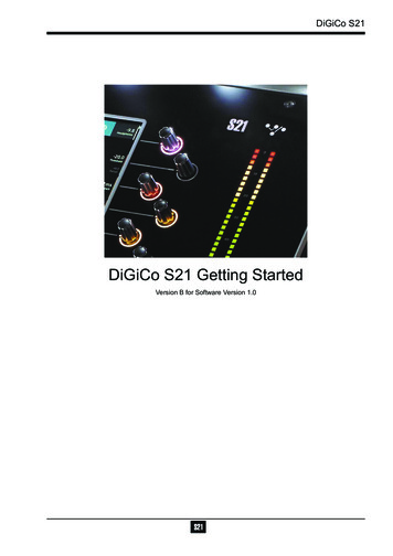
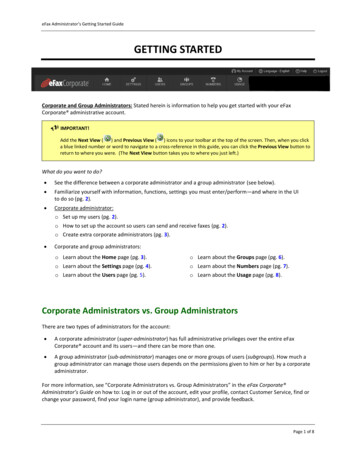
SD12 - Getting StartedRear PanelDual PSUOptocore(Optional)Word Clock I/OUSB AudioMADI I/OGPI/OMIDI IN/OUT/THRU8 AES I/O8 Mic/Line In8 Line OutDVI O/View Output4 x Console USBDMI Slot 1 DMI Slot 2Console EthernetPC ResetIP Addresses on an SD12The SD12 Engine board contains 2 devices that require an IP address. The Console PC and the Host Interface controller.Both devices' IP addresses are displayed in the console diagnostics tab.NOTE: These IP addresses will be set to appropriate values when the console is shipped and they should not bechanged in normal operation.The IP Addresses for these devices can however be set using SD12Network.exe located in the D:\SD12 folder. A shortcut to this program is available in the Windows start menu.This program allows the user to enter a single IP and subnet mask. This is the IP for the Console PC and the application will automatically set the Host Interface controller's IP to the correct sequential Address.Once the required IP or Subnet has been entered, a console power cycle is required for the change to take effect. Pressing the OK andShut Down button will initiate the Shut Down Procedure.1-8
SD12 - Getting Started1.3.2 Layers and Banks.The SD12's worksurface is divided into Layers and Banks. Each Bank contains twelve channels, and the channels which are currentlyactive on the control surface are defined using the fader bank and bank layer buttons to the right of the Channel Strip section’s faderNOTE: There is also a Master Screen Assign button above the Layer and Bank buttons on the right section which isused to switch the right hand section to diplay the Master ScreenA ‘bank’ is a set of twelve faders, and a ‘layer’ contains up to four ‘banks’. There are up to 3 ‘layers’ in each section of the deskPressing the bank layer button, located above the fader bank buttons, toggles between layers.To access a bank of faders within that layer, press the appropriate fader bank button. To switch both sections of the console to thesame bank level, press and hold one of the fader bank buttons.The specific channels which are contained within each Bank are defined in the Layout Fader Banks display. By default, the Inputchannels will be assigned to Layer 1 on the left and right sections of the console. The different output channels will be assigned to Layer2. Control Groups will be assigned to Layer 2. These bank assignments can be customised by the user and saved in a session at anytime. Holding any bank or layer button down for a couple of seconds will switch both worksurface sections to the same bank level orlayer.1-9
SD12 - Getting Started1.3.3 Using the Control Surface.There are two main ways in which all of the functions of the SD12 are accessed:1. The touchscreen display, which can be controlled directly using a finger, or by using the keyboard and mouse2. The physical encoders, switches and faders.Note that when touching the screen directly, you may find it easier to use a finer point than your finger. However, inorder to prevent damage to the screen, it is important that you only use devices specifically designed for touchingscreens (such as a pda stylus), and that you never press down hard on the screen.A number of functions can be accessed in different ways, allowing users to operate the console using whichever interface they prefer.This manual will describe accessing on-screen functions by touching the screen directly and not by using the mouse.All of the physical controls are described in full within the relevant section of the manual and many require no further introduction.The Master screen has a row of grey buttons across the top, which are used to access a range of configuration displays. Pressing thesebuttons opens either a further drop-down sub-menu or a pop-up display. If a drop-down menu is opened, pressing on one of its entrieswill open a pop-up display. The buttons lighten to indicate that their sub-menu or pop-up display is open. A number of the buttons withineach pop-up display generate further pop-ups.Generally, buttons within the pop-ups are coloured grey when their function is inactive, switching to a colour when their function isactive. Pressing on a text box opens a numeric or QWERTY keypad which can be operated directly by pressing the screen or via theconsole’s external keyboard.Pop-ups are closed by pressing the box in the top right-hand corner of the pop-up, marked CLOSE or CANCEL (or by pressing CAN onkeypad pop-ups).On the Right Panel is a single encoder marked Touch-Turn (shown below). This is used to access any rotary controls within the MasterScreen. To assign the Touch-Turn encoder to a particular on-screen pot, touch the pot to be assigned. You will notice that a colouredring appears around the on-screen pot, indicating that it is assigned to the Touch-Turn encoder. The colour of this ring is unique to thatcontrol, and is also reflected in the base of the Touch-Turn encoder, providing further indication of which pot is currently assigned to it.The Master Screen button in the right section switches the right screen view from the Master Screen to the bank of channels which areselected in the right section.1.3.4 The Assigned Channel.One of the channels in the Channel Strip panel is displayed in gold, indicating that it is currently the Assigned Channel. This meansthat it has been assigned to the worksurface controls and can be configured in detail, as described below. To Assign a channel, touchanywhere in the channel on the screen (except the Aux Send area).Alternatively, use the ch left and right buttons at the bottom of the channel worksurface controls to scroll through the channels in thepanel:Note that these left and right arrows are duplicated in the channel Setup and Output displays.Note also that the Channel List display provides another method for assigning a channel to the worksurface controls.1-10
SD12 - Getting StartedOnce a channel is assigned, all of the controls for that channel which are not displayed within the channel strip itself can be accessedvia secondary pop-ups, displayed by touching inside the relevant area of the channel. These pop-ups include controls such as input andoutput routing and signal processing parameters.A number of the physical rotary encoders on the control surface can be assigned to different on-screen pots. In order to ensure that it isclear which function is assigned to which encoder, the assigned on-screen pot will have a coloured ring around it which will be reflectedin the colour of the light around the base of the encoder on the control surfaceThe 2 rows of twelve encoders and buttons immediately below the touchscreen (shown above) refer to the channels with which they arealigned.Pressing one of the Quick Select buttons on the left of the screen will assign the selected function to the top row of these controlsbelow the screen. Six aux sends can be displayed in the Channel Strip panel at any one time. If more than six aux sends have beencreated in the session, the scroll button outside the bottom left-hand corner of the screen can be used to scroll the display through theremaining auxilaries.1-11
SD12 - Getting StartedThe controls to the right of the Channel Strip panel allow the Assigned channel to be adjusted:The top half of the channel worksurface controls (down as far as the insert a, insert b and direct buttons, as shown above) control thesignal processing parameters which are displayed in the pop-ups accessed by touching in the appropriate section of the active channel.The bottom half of the channel worksurface controls is concerned with output routing.To the left of the screen are more channel controls: When pressed, the 2nd function button allows access to different parameters:1) Stereo Aux Pan and Pre/Post switching2) Hard Mute of a channel3) Switching of LR or LCR panning2nd function is indicated by a green 2nd Function display appearing in the bottom left-hand corner of the screen, as well as by the 2ndfunction button lighting with a ring of green.The Option/All button has 2 main functions:1) When pressed and released, any channel that is a member of a gang or Multi will be temporarily isolated from that gangor Multi.2) When pressed and held, any parameter that is adjusted on a single channel will also be adjusted in the same way on allof the channels in that bank1-12
SD12 - Getting Started1.3.5 The Master Faders.By default, the left hand fader of the two in the bottom right corner of the worksurface is assigned to the Master buss, which is the loweststereo group output by default.Also by default, the right hand fader is assigned to Solo Buss 1In addition, these faders can be reassigned to control any input channel or buss of your choice using the Layout Fader Banks panelPress the Assign L or Assign R buttons and the Channel List will be displayed.Select a channel by touching its entry in the Channel List and it will be assigned to the relevant Master FaderThese faders can also be unassigned (set to empty) by pressing the Unassign L or Unassign R buttonsLayout Fader BanksAssignMasterFadersSelecta Channel1-13
SD12 - Getting Started1.3.6 Channel Types.The SD12 has 4 different channel types which are laid out in banks of 12 on the console worksurface and can be identified by theircolour.By default, the Input Channels will be assigned to Layer 1 on the left and right sections of the console.The output channels (Groups, Auxes and Matrices) will be assigned to Layer 2.Control Groups will be assigned to Layer 2. These bank assignments can be customised by the user and saved in a session at any time.Holding any left or right section bank or layer button down for a couple of seconds will switch the left and right worksurface sections tothe same bank level or layer.The controls on each different type of output channel are identical but an input channel has a number of additional of features.InputsInput Module - Touch to ExpandAnalogue Gain/Digital TrimPhase - Gain TrackingMain/Alt Input SelectHPF/LPFInsert A Routing & On/Off4 Band Dynamic EQTouch To ExpandMultiband DynamicsTouch To ExpandInsert B Routing & On/OffAux SendsTouch to Assign RowsChannel PanMute IndicatorsChannel LabelRouting Module - Touch to ExpandGang & Safe Indicators1-14GroupsAuxesMatrix
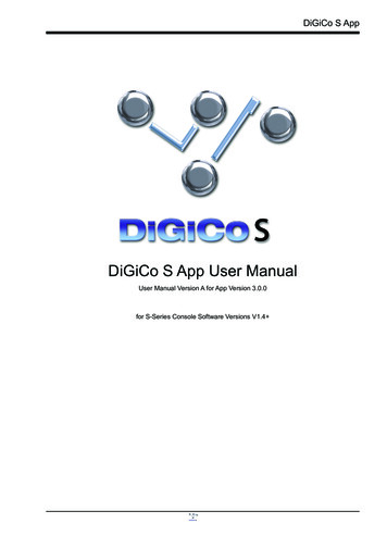
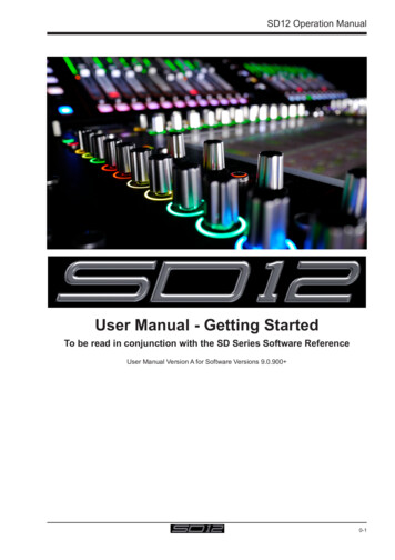
SD12 - Getting Started1.4 Hardware Configuration1.4.1 Connections.Detailed information on the various systems of connection is provided in the relevant chapter of this and the "Software Reference"manual but the following diagram provides an overview of a single console/single rack setupCONNECTION WITH MADISD Rack / DiGiRackMAIN MADI OUTMADI PORT 1 INMADI PORT 1 OUTMAIN MADI INCONNECTION WITH OPTICAL FIBREOPTO AOPTO AOPTO BOPTO BOPTIONALREDUNDANTLOOPOPTO AOPTO BAll connections should be made before switching on the console and racks.The console and rack each have dual redundant power supplies and both should be switched on at all times. After switching on theconsole the software will be launched automatically and the state of the worksurface and settings should be the same as when it waslast Shut Down.To Shut Down the console press the System Shut Down button and wait until you receive a message saying that it is safe to switchthe power off.The SD12 worksurface has 8 analogue I/O and 8 AES I/O on its rear panel (referred to as Local I/O) and additional I/O is supplied in theform of remote Racks which can each accommodate up to 56 inputs and 56 outputs in different formats. These racks are connected tothe worksurface by either 100M high specification 75 Ohm coaxial cables fitted with BNC connectors or optical fibre. The Racks havetwo pairs of MADI connectors - Main MADI IN & OUT and AUX MADI IN & OUT.In normal operation the MADI connections should be as follows (see diagram above):Rack MAIN MADI IN connected to the console MADI 1 OUTRack MAIN MADI OUT connected to the console MADI 1 INAt 48KHz, the console's other MADI Port can be connected to a MADI recorder (See Audio I/O Panel for setup details) or a secondDiGiCo Rack or console.1-15
SD12 - Getting Started1.5 Software ConfigurationThe SD12 has a default setup which means that the new user need not get involved in configuring the desk at this stage. However, hereis a brief overview of how the different displays are used in putting together a session. Each of the master displays introduced below aredescribed fully within the rest of the manual.The Files Templates display is used for loading pre-configured session templates.The Files Session Structure display is used for configuring how the console’s audio channels are to be divided between channeltypes, and where the format of the channels is definedThe Session Structure display can be used to automatically assign the channels to the worksurface. However, channels can also bemanually added to the worksurface using the Layout Channel List display.The Setup Audio IO display is used to configure the physical I/O connected to the SD12, including configuring and naming the sockets of the option cards installed in racks, and the setting of pads and phantom power.1.5.1 Templates.If any templates have been created, they provide an easy starting point for sessions which are already customised to your context. Toload a session template, open the Session Templates display by selecting the Templates option at the top of the Files menu. Nowtouch the template you wish to load from the list shown, and press OK.1.5.2 Session Structure Overview.When starting a new session from scratch, it is important to decide how many of each type of channel is required. While changes to session structure can be made once a session has been started, it is best to try and set these parameters before configuring the session.The structure will set items such as the number of input channels, the number and type of aux channels and group channels availableSet Order of Aux andGroup bussesTouch number’s toedit with pop-upkeypad or touchturnSelect sessionsample rateEnter Session titleSet number of Input ChannelsSet number and type of AuxSet number and type of GroupTotal numberof unallocatedprocessingTotal numberof sparebussesBegin by setting the sample rate at the top of the panel. There are a total of 72 input channels available and 36 busses (plus a Masterbuss which can be stereo or LCR).Channel resources can be split into input or output channels in almost any configuration. The default configuration is :48 input channels (Input channel formats are defined within each channel, not within the Session Structure)6 Mono Aux busses & 6 Stereo Aux busses6 Mono Group busses & 6 Stereo Group busses12 Matrix Inputs and 8 Matrix Outputs12 Control GroupsNote that a Talkback channel is also assigned to the control surface, though it isn't configurable within the SessionStructure and is therefore not displayed there.To adjust any of the channel allocations, touch on the associated channel count box, and either enter a number using the pop-up number keypad, or adjust using the assigned touch turn controller.Clear All Buttons : When changing routing, you have the option of clearing any non-default routing or processing (EQ, dynamics etc)1-16
SD12 - Getting Startedfrom the channels in the session. This is especially useful when restructuring an existing session to make a new session. The other'clear' buttons in the display perform similar operations.Aux Sends and Direct Sends : By toggling the state of the Aux Sends and Direct Sends Buttons in the Input Channels section, it ispossible to change the default operation of the Aux Sends and Direct Sends. These functions toggle between “Post Fader”, “Pre-Fader”and “Pre-Mute”.Aux Order and Group Order : The Aux Order and Group Order buttons open a second window, providing you with the ability to changethe order of auxes and groups. By default, mono busses come first, followed by stereo busses. The Master buss is the first stereo buss,regardless of the order you place the busses in.Auto-Route : The Auto-route functions automatically routes consecutive inputs for input channels, and consecutive outputs for busses.For example, auto-routing 72 inputs will route the first physical input (eg 1:Mic 1) to input channel 1, the second physical input (1:Mic 2)to input channel 2 until you either run out of inputs or channels. Auto-routes are as follows :Input Channels auto-route with physical inputsAux, Group and Matrix Channels auto route to physical outputsMatrix Inputs auto-route with group outputsNOTE : Auto-Routing can only be used in conjunction with the “Clear All” button.Rebuild Banks : When changing the number of allocated channels in any section (input channels, busses etc), you can restructure thesession without rebuilding banks, meaning that any additional channels you have allocated will not be “placed” on the worksurface, andneed to be manually assigned to faders. If however, you restructure a session with Rebuild Banks (either Horizontally or Vertically)enabled, the worksurface will be built with all channels available on the worksurface in a default layout. Rebuilding horizontally will resultin input channels being spread across the top layer of both sides of the console, using as many banks as required, with output channelsbeing assigned to Layer 2. Rebuilding vertically will result in input channels being assigned to Layer 1 on the left side of the console,and output channels to Layer 1 on the right.1.5.3 Audio I/O Overview.The Audio I/O window is used to configure the physical I/O connected
SD12 Operation Manual 1 0-1 User Manual - Getting Started To be read in conjunction with the SD Series Software Reference User Manual Version A for Software Versions 9.0.900