Transcription
DiGiCo S21DiGiCo S21 Getting StartedVersion B for Software Version 1.0
DiGiCo S21
DiGiCo S21Copyright 2015 Digico UK LtdAll rights reserved.No part of this publication may be reproduced, transmitted, transcribed, stored in a retrieval system, or translated into any language inany form by any means without the written permission of Digico UK Ltd. Information in this manual is subject to change without notice,and does not represent a commitment on the part of the vendor. Digico UK Ltd shall not be liable for any loss or damage whatsoeverarising from the use of information or any error contained in this manual.Software License NoticeYour license agreement with Digico UK Ltd, which is included with the S21 console product, specifies the permitted and prohibited usesof the product. Any unauthorised duplication or use of Digico UK Ltd software, in whole or in part, in print or in any other storage andretrieval system is prohibited.Licenses and TrademarksThe S21 logo and S21 name are trademarks. Digico UK Ltd and the Digico UK Ltd logo are registered trademarks of Digico UK Ltd.Digico (UK) LtdUnit 10Silverglade Business ParkLeatherhead RoadChessingtonSurreyKT9 2QLEnglandTelephone: 44 (0)1372 845600Fax: 44 (0)1372 igico.bizManual Issue and Date: Issue B - September 2015 - For Version 1.0Software Licence Agreement"Product":S-Series software product produced by Digico UK Ltd intended for use on Target Platform identified below."Target Platform": Digico S-Series Digital Console systems.1.2.3.4.5.6.7.8.9.In return for the payment of the one-time fee, the Customer (identified at the end of this Agreement) receives from Digico UK Ltd alicence to use the Product subject to the following terms and conditions.The Product may be used without time limit by the Customer on the Target Platform.The Customer must register the Product with Digico UK Ltd. Registering the Product is deemed an acceptance of the terms andconditions in this agreement.The Product and its licence are not transferable, and the Customer is not permitted to onward-license to any third party. The Customer indemnifies Digico UK Ltd against any and all claims and actions arising from third party use of copies of the Product made bythe Customer.The Customer agrees not to attempt to decompile the object code of the Product otherwise than in circumstances specifically provided for by law, and then only after consultation with Digico UK Ltd.The Customer agrees not to use, or licence the Product for use, with equipment other than the Target Platform.The Customer agrees not to modify the Product without the prior written consent of Digico UK Ltd.This Agreement applies to any enhancement or upgrades that may become available for the Product.This Agreement does not transfer any right, title, or interest in the Product to Customer except as specifically set forth herein.Digico UK Ltd reserves the right to terminate this Agreement upon breach, in which event Customer shall thereafter only be authorised to use the Product to the extent that its contractual commitments to third parties require and then only where such commitments relate to use of the Product as authorised in the foregoing provisions of the Agreement.LIMITED WARRANTY - Digico UK Ltd warrants for a period of 1 year from the date of purchase of the Product, the Product will reasonably execute its programming instructions when properly installed on the Target Platform. In the event that this Product fails to executeits programming instructions during the warranty period, the Customer's remedy shall be to return the Product to Digico UK Ltd forreplacement or repair at Digico UK Ltd option. Digico UK Ltd makes no other express warranty, whether written or oral with respect ofthis Product.LIMITATION OF LIABILITY - Except as otherwise expressly provided by law, (a) the remedies provided above are the Customer's soleand exclusive remedies and (b) Digico UK Ltd shall not be liable for any direct, indirect, special, incidental, or consequential damages(including lost profit whether based on warranty, contract, tort, or any other legal theory.)This agreement is made under the Laws of England.LICENCE NO: .REGISTRATION DATE: .
DiGiCo S21Contents1.1 The Console .1-11.2 Before You Start .1-21.2.1 Worksurface Layout .1-21.2.2 Layers and Banks .1-31.2.3 Using the Control Surface .1-31.2.4 The Selected Channel .1-41.2.5 The Under Screen Controls .1-41.3 The Expanded Views .1-51.3.1 Display Expanded Views .1-51.3.2 Channel Setup View .1-61.3.3 Group and Aux Setup View.1-71.3.4 Input Routing View .1-71.3.5 EQ View .1-81.3.6 Dynamics 1 View .1-91.3.7 Dynamics 2 View .1-101.3.8 Control Group Setup . .1-111.3.9 Solo Channel Setup.1-121.4 Customising the Layout.1-131.4.1 The Console Overview .1-131.4.2 The Spill Set .1-131.4.3 Swap Banks .1-141.4.4 Set Master .1-141.5 The Main Menu.1-151.5.1 Session Management .1-151.5.2 Snapshots .1-161.5.3 Preferences .1-181.5.4 Audio Sync .1-181.5.5 Macros .1-191.5.6 FX Rack .1-191.5.7 Graphic EQs .1-201.5.8 Matrix .1-201.5.9 System .1-211.5.10 Diagnostics .1-221.5.11 Restart or Shutdown .1-221.5.12 Upgrading Software .1-22
DiGiCo S211.1 The ConsoleThe Digico S21 consists of a worksurface, an audio engine and a range of onboard inputs and outputs. It can be connected using optional DiGiCo DMI Cards to a variety of DiGiCo racks and other audio input/output devices.The console worksurface consists of 2 sections that can be configured to control up to 40 mono or stereo input channels, 10 VCAs, 16mono or stereo busses plus a Master buss and a 10 Input x 8 Output Matrix.The left and right sections have 10 assignable faders and 10 sets of assignable on-screen channel controls, the right hand sectionalso has a dedicated Master fader and mute, a Master/Solo meter, a set of 6 assignable encoder/switches and worksurface navigationcontrolsThe console's buss architecture is dynamic, and can support mono and stereo configurations.Multiple console setups can provide:Front of House and Monitoring with shared stage racks and gain tracking.1-1
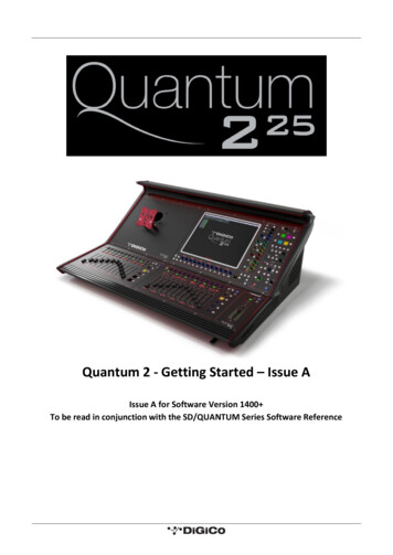
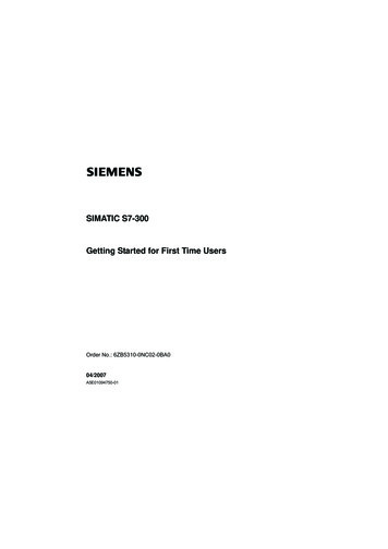
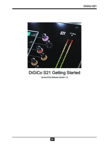
DiGiCo S211.2 Before You StartThere are certain general operating principles and terms that should be understood before continuing to use this manual.Please read this chapter carefully before proceeding.IMPORTANT NOTES:S21 V1.0 software is not compatible with any sessions created in preliminary (pre V1.0) versions of softwarePlease delete all old sessions to avoid potential issues and create a "New" session in V1.0.The console power switch is situated on the rear panel.Please ensure that any required DiGiCo I/O racks are connected to the console DMI cards and powered on before starting the console itself to enable automatic discovery of the racks.DMI cards are NOT "Hot swappable" so please ensure that the console is powered off before inserting or removingthem.We recommend that the first snapshot is used as a "Setup" Snapshot where all of your "session wide" settings likerouting, Control Group membership and Buss Modes (whether Busses are Groups or Auxes) are first stored.Because these types of setting can be changed with Snapshot recall, it is advisable to save them all into this firstsnapshot before creating any further Snapshots. In this way, the settings for all subsequent Snapshots will contain thesame data and there should be less requirement to adjust the Safe settings in the channels.1.2.1 Worksurface Layout .Assignable Encoder/SwitchesMultiTouch ScreenMaster/Solo MetersAssignable Encoder/SwitchesHeadphone LevelSnapshot Previous/NextSolo & MuteMaster FaderChannels FadersSpill SetOverviewLayer Up/DownRear PanelWord Clock I/OConsole EthernetAES I/OGPI/ODVI Screen OutputSEE NOTE BELOWUB MADI Connector12 Line Out24 Mic/Line InDMI Slot 1DMI Slot 2Console USBIMPORTANT NOTE: The DVI Screen output will display a copy of the Master (right hand) screen but this must beconnected to the HDMI input of a suitable monitor using a standard DVI to HDMI adaptor (not supplied).IMPORTANT NOTE: The GPI/O functionality is not yet implemented in V1.01-2
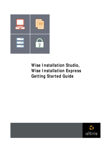
DiGiCo S211.2.2 Layers and Banks .The S21's worksurface is divided into Layers and Banks. Each Layer contains 2 Banks of 10 channels, and the layer which is currentlyactive on the control surface is selected using the layer up and down buttons next to the Master fader.The right hand screen is referred to as the Master Screen and this is where the various expanded views of elements such as EQ andDynamics are displayed.Pressing the white Overview button, located near the layer up and down buttons displays an on screen representation of all consolechannels and the active layer can also be selected by touching it on the screen in this mode.The specific channels which are containedwithin each Bank are defined in the Overview display. By default, the Input channels will be assigned to Layers 1 and 2 on the left andright sections of the console.The different output channels will be assigned to Layer 3 and 4. Control Groups will also be assigned to Layer 4. These bank assignments can be customised by the user and saved in a session at any time.1.2.3 Using the Control Surface .There are two main ways in which all of the functions of the S21 are accessed:1. The touchscreen display, which can be controlled directly using a finger2. The physical encoders, switches and faders.A number of functions can be accessed in different ways, allowing users to operate the console using whichever interface they prefer.All of the physical controls on the console worksurface are described in full within the relevant section of the manual and many requireno further introduction.The right hand Master Screen has a DiGiCo logo icon at the top which is used to access the Main MenuMain Menu1-3
DiGiCo S211.2.4 The Selected Channel .One of the channels in the Channel view is displayed with a highlighted background, indicating that it is currently the Selected Channel.This means that it has been assigned to the worksurface controls to the right of the screen as shown in the image below. To assign achannel, touch in the Output Block at the bottom of the on screen Channel viewNOTE: All of the master and under screen rotaries are encoders and switches in one unit.Often, different functions can be accessed by a standard turn, a push turn and a push (switch)eg Standard turn Gain control & Push turn Trim controlSelected ChannelAssignable Encoder/SwitchesGain & Trim (Push Turn)HPFCompressor ThresholdGate ThresholdAux Pan (Stereo)Aux LevelOutput Block areaTouch here to select a channelNOTE: When the right hand screen is not displaying the Channel view (eg it is displaying an EQ view), the masterscreen worksurface rotaries will not be assigned to the Channel view controls but to the controls for the EQ or otherexpanded view instead.1.2.5 The Under Screen Controls .Selected ChannelBlue Pan - Default assignmentTouch and Hold in this rowAssigns HPF Freq and On/Offand highlights in MauveTouch and Hold in this rowAssigns Dynamics 2 Threshold and On/Offand highlights in YellowTouch and Hold in this rowAssigns Gain/Trim and highlights in RedTouch and Hold in this rowAssigns Dynamics 1 Threshold and On/Offand highlights in GreenTouch and Hold any AUX rowAssigns Aux Send & On/OffTouch the selected channelin this row to return todefault Pan assignmentThere is a row of 10 encoder/switches immediately below each touchscreen (shown above) that refer to the channels with which theyare aligned.1-4
DiGiCo S21These controls give access to the channel pans in standard operation and the surrounding coloured LED rings are blue.Touching and holding on the rows of controls on screen assign these encoders to different parameters, the screen row changes colourand the LED rings change to a similar colour.In the above example the Gain/Trim row at the top of the Channel View has been touched, the row is highlighted in red and the underscreen controls are assigned to the Gain/Trim function.Other possible assignments are:HPF Frequency & On/Off - Row and LED ring highlighted in MauveDynamics 1 Threshold & On/Off - Row and LED ring highlighted in GreenDynamics 2 Threshold & On/Off - Row and LED ring highlighted in YellowSelected Aux row Send level & On/Off - Row and LED ring highlighted in Purple1.3 The Expanded Views1.3.1 Display Expanded Views .A single touch (rather than a touch and hold) will open a number of different expanded views according to where the touch is made.Opens Channel Setup viewOpens EQ viewOpens Dynamics 1 viewOpens Dynamics 2 viewTouch any Aux Send to select the channeland assign the selected Aux Send to the6th Master Rotary & Aux Pan to the 5th(with Aux To Faders option OFF)Swipe vertically to display more AuxesTouch here to select a channelThe image above shows the various touch areas in the Channel view and the expanded view will be displayed on the Master screen.Note: When an expanded view is already open, selecting a different channel by touching the Output block area at thebottom of the screen will change the expanded view to display the newly selected channel.If an expanded view is already open and a different expanded view is selected, the last view selected will be displayedon the Master screen with the previously expanded view behind it.Any combination of expanded views can be "layered" in this way.The Close All button on the Master screen can be touched at any time to close all active expanded views.The Close button on the Master screen can be touched at any time to close the currently active expanded view and display the viewbeneath it.1-5
DiGiCo S211.3.2 Channel Setup View .Channel Mono/Stereo switchGain Tracking On/OffAdd To SetOpen Safes ViewSelect Solo AssignmentChannel NameColumnTitle LabelSwitch to EQ ViewSelect input sourceFiltersDelayTubesInsert AEQDyn 1Dyn 2Master RotaryAssignmentInsert BAuxesDirect OutGroupsTouching the input block at the top of the channel opens the Channel Setup viewEach column represents a section of the channel processing strip and these columns can be selected by touching their title label.Once a column is selected, the parameters available in that section are assigned to the worksurface Master Rotaries to the right of thescreen.Some columns are subdivided into blocks eg Input processing consists of Filters, Delays and Tubes.Touching any of these blocks will assign the Master Rotaries to the settings for that block.Note that touching the Filter block or the EQ block will both display the EQ view but with different bands selected.Note: When any expanded view is open on the Master screen, the Master Rotaries no longer have their standard default assignment and are instead assigned to the parameters in the expanded view which is currently displayed.The buttons in the top bar provide the following functions:Switching the channel from Mono to Stereo modeAdding the channel to a Spill Set (see Spill Set section later in this document)Switching Gain Tracking On/Off for the channelOpening the Safes View which allows channel parameters to be protected from Snapshot RecallSelecting which Solo Busses the channels are assigned toTouch the keyboard icon at the top left of the screen to enter a channel name.Touch the Equaliser button at the bottom left of the screen to switch to the EQ view for the currently selected channel.To select an Input Route touch the block below the Source label and the Input routing view will open.To select an Output Route touch the Direct Output block in the Outputs column and the output routing view will open.To assign the channel to a Group buss touch the Group Assigns button in the Outputs columnTo view and adjust Aux Send Options for the channel touch the relevant Aux Sends button in the Outputs column1-6
DiGiCo S211.3.3 Group and Aux Setup View.The Group and Aux Channel Setup view are very similar to the Input Channel version but they have one extra function that is used toconvert a Group Buss to an Aux Buss or vice versaThe S21 has a fixed number of output busses but they can be changed at any time to be either Auxes or Groups.In the example below, touching the Mode button on the Group Setup view will change the Group to an Aux but there is warning that allchannel assignments will be reset in the process. So the newly converted Aux will be flattened.The situation is exactly the same when converting an Aux to a Group - all assignments are resetNote: In S21 V1.0, Aux/Group Mode can be changed with a Snapshot recall and is part of the Fader, Mute, Mono, CGmember Safe block. Please ensure that the buss modes are set in your first Snapshot before you create any furtherSnapshots. This will ensure that the buss mode settings will be consistent in all Snapshots.Change Group to AuxWarning1.3.4 Input Routing View .Touching the Source area on the Channel Setup will open the Input Route expanded view.Only input channels have a Source selection - output channels sources are fixed within the systemTo select an input source, touch one of the buttons in the port list on the left of the screen and the relevant sockets will be displayed.Now touch to select a socket in the socket display.Inputs can be routed into multiple channels at the same time using the Ripple Route function.Touch the Ripple Route button in the top bar and then select the first and last sockets in the required range - then press the OK button.The Master Rotaries are assigned to the Gain/Trim, 48V and Input Pad controls if they exist for the socket type selected.Note: Ripple routes are automatically done in the channel display order rather than channel number order.Ripple RouteSelect PortandSocket TypeChannel Mono/Stereo switchSelectSocketRoutingDetailsMaster RotaryAssignment1-7
DiGiCo S211.3.5 EQ View .Touching the EQ area on either the Channel view or the Channel Setup will open the EQ expanded view.The EQ band can be selected by touching the band icons on the left of the screen or by touching the bands on the EQ graph itself.The graph has 2 modes, 4 band EQ or filters. Touch the relevant band and the adjust the parameters by dragging the band icon on thegraph.While an EQ band is selected, it can be "pinched" on screen to adjust the Q setting.The selected band's parameters can also be adjusted with the Master Rotaries to the right of the screenThe buttons in the top bar provide the following functions:EQ On/OffCopy EQ to another channel(s) - touch the button and select the destination channels from the channel picker - OK to confirmFlatten EQCopy EQFlatten EQEQ On/OffSwitch to Channel SetupSelect EQ bandSwitch to Dyn 1 ViewSelect FiltersDrag to adjust1-8Select EQ BandDrag to adjustMaster RotaryAssignment
DiGiCo S211.3.6 Dynamics 1 View .Touching the Dynamics 1 area on either the Channel view or the Channel Setup will open the Dynamics 1 expanded view.Dynamics 1 can be a Single Band or Multiband Compressor (on 4 channels). Touch the Mode button in the top bar to switch modes.Multiband Dynamics has 4 viewing modes, one for each individual band and one that displays all 3 bands at the same time. These areselected with the buttons on the left of the screen.Parameters can be adjusted on-screen or using the Master Rotaries to the right of the screen.The buttons in the top bar also provide the following functions:Dynamics Module On/OffCopy Dynamics settings to another channel(s) - touch the button and select the destination channels from the channel picker - OK toconfirmReset Dynamics moduleSelect ModeDYN 1 On/OffCopy DYN 1Reset DYN 1Switch to EQ viewSwitch to Dyn 2 viewAdjustParametersSelect ModeDYN 1 On/OffMaster RotaryAssignmentCopy DYN 1Reset DYN 1Switch to EQ viewSelect bandMultiBand viewSwitch to Dyn 2 viewAdjustParametersSelect ModeDYN 1 On/OffMaster RotaryAssignmentCopy DYN 1Reset DYN 1Switch to EQ viewSelect bandMultiBand viewSwitch to Dyn 2 viewAdjustParametersMaster RotaryAssignment1-9
DiGiCo S211.3.7 Dynamics 2 View .Touching the Dynamics 2 area on either the Channel view or the Channel Setup will open the Dynamics 2 expanded view.Dynamics 2 can be a Keyed Gate, a Ducker or Single Band Compressor with Side Chain.Touch the Mode button in the top bar to switch modes.Dynamics module 2 provides side chain access via a selectable input - this can be used for external triggering.Select the Source signal by touching the Key/Side Chain input button on the left of the screen and select a source from the standardinput routing list.Then use the Self/Ext button to activate this function.Parameters can be adjusted on-screen or using the Master Rotaries to the right of the screen.The buttons in the top bar also provide the following functions:Dynamics Module On/OffCopy Dynamics settings to another channel(s) - touch the button and select the destination channels from the channel picker - OK toconfirmReset Dynamics moduleSelect ModeDYN 2 On/OffCopy DYN 2Reset DYN 2Switch to DYN 1 viewGate statusSelect Key SourceKey Input On/OffMeter and Key FilterAdjustParametersSelect ModeSelect DYN 2 Mode1-10Master RotaryAssignment
DiGiCo S211.3.8 Control Group Setup .To create a Control Group, touch the top of a Control Group Channel to open the CG Setup viewTouch the Edit button in the top barSelect the required CG members by touching them in the Channel Picker and touch the OK buttonThe CG Setup view will now show blocks representing each of the CG members and the CG channel will display a list of its memberswith their fader levelsSetup CGWarningEdit CGSelect CG Members and Touch OK1-11
DiGiCo S211.3.9 Solo Channel Setup.The S21 has 2 Solo busses which have their own control channels in the console layout normally located on the 4th layer next to theMatrix Output channels.Note: Both Solo busses 1&2 are both sent permanently to the console headphone socket.When no channels are soloed, the Master Buss (No Solo source) will always be sent to Solo Buss 1SoloChannelsPFL/AFLStereo ModeMulti/SingleMonoModeSwitchRoute SoloDirect OutTouching the top of either Solo channel will open the relevant Solo setup viewVarious Solo buss settings can be found in the top bar of this viewSolo busses can be switched Mono or StereoThey can be set to PFL or AFL modeThey can be set to Multi Mode where multiple solos can be switched on at the same time or Single Mode where switching one solo onwill cancel previously active SolosAny channelcanMono/Stereobe assigned toSolo Buss1, 2Trackingor both 1&2.ChannelswitchGainOn/OffOpen the channel setup view for any channel and there is a Solo buss assignment button in the top bar.Add To SetOpen Safes ViewSelect Solo AssignmentChannel NameColumnTitle LabelSwitch to EQ ViewSelect input sourceFiltersDelayTubes1-12Insert AEQDyn 1Dyn 2Master RotaryAssignmentInsert BAuxesDirect OutGroups
DiGiCo S211.4 Customising the Layout1.4.1 The Console Overview .Pressing the white Overview button, located near the layer up and down buttons displays an on screen representation of all consolechannels. This view can be used to change the layout of the console channels and banks.Touching the Edit button in the top bar changes the appearance of the display and activates drag and drop capability.Any block that represents a channel can be dragged to another position and dropped there. This will overwrite the channel in that position and the overwritten channel will reappear in the Unassigned Channels section at the bottom of the left screen.Channel blocks can also be dragged directly to the Unassigned Channels section to remove them from the worksurfaceNote: Channel blocks can be dragged between the 2 console screens1.4.2 The Spill Set .In Edit mode, a selection of up to 10 channels can be dragged to the Spill Set section at the bottom of the right hand overview screen tocreate a Spill Set.Typically, these would be channels to which the user needs to have quick access at all times.When a Spill Set has been created, the worksurface button located above the overview button will become blue and pressing this buttonwill display the Spill Set channels on the right hand screen. pressing again hides the Spill Set.1-13
DiGiCo S211.4.3 Swap Banks .In Edit mode, touching the Swap Banks button in the top bar allows complete banks to be moved from one position to another eitherfrom left to right or from one layer to another.Swap Banks1.4.4 Set Master .In Edit mode, touching the Set Master button in the top bar allows a bank to be selected that will be locked to the right hand consolescreen. press the Set Master button and then touch the required bank.In this mode, all other banks are assigned to the left hand console screen and can be accessed using the worksurface layer up anddown buttons. Once a Master is set, it can be cleared by touching the Clear Master button in the top bar.Set Master / Clear Master1-14
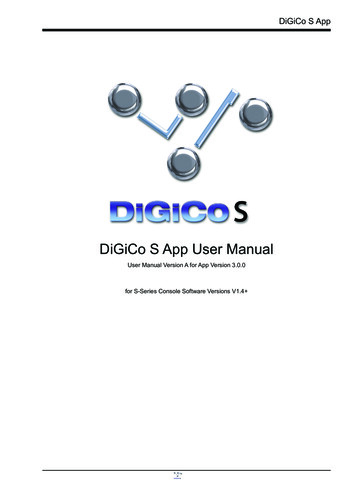
DiGiCo S211.5 The Main MenuThe right hand Master Screen has a DiGiCo logo icon at the top which is used to open the Main MenuThe Main Menu contains a number of buttons which are used to access various console functions1.5.1 Session Management .Touching the Sessions & Snapshots button opens a display which contains file management functions in the top bar and Snapshotcontrol in the main area of the screen.Save SessionSave As New FileLoad SessionCreate New SessionSnapshot hasunsaved changesSession NameEdit ModeCurrent Snapshot - RedSnapshotAuto UpdateFireButtonSelected Snapshot - GreyInsert NewSnapshotSnapshotNameUpdateSnapshotTo create a new session, touch the New button in the top bar and a progress bar will be displayed.When the process is complete, touch the Save As button, select the internal drive (labelled Home) or the USB port (with a USB keyinserted into the console USB port) and touch the Save Here button.Then type a new session name using the on-screen keyboard and touch the Done button.To update the session after the initial Save As process, just touch the Save button and the current session will be updated automatically.To load an existing session, touch the Load button, select the internal or USB drive and then select the required session from the listand touch the OK button.NOTE: The Auto-Update button on the left of the screen relates to Snapshots and not to SessionsWhen active, this function will automatically update the current Snapshot as changes are made on th
DiGiCo S21 1-1 1-1 1.1 The Console The Digico S21 consists of a worksurface, an audio engine and a range of onboard inputs and outputs. It can be connected using op-tional DiGiCo DMI Cards to a variety of DiGiCo racks and other audio input/output devices.