Transcription
DiGiCo S-Series User Guide – Issue JIssue J for Software Version 2.5
DiGiCo S-Series User Guide – Issue J
DiGiCo S-Series User Guide – Issue JCopyright 2019 Digico UK LtdAll rights reserved.No part of this publication may be reproduced, transmitted, transcribed, stored in a retrieval system, or translated into any language in any form by anymeans without the written permission of Digico UK Ltd. Information in this manual is subject to change without notice, and does not represent acommitment on the part of the vendor. Digico UK Ltd shall not be liable for any loss or damage whatsoever arising from the use of information or anyerror contained in this manual.Software License NoticeYour license agreement with Digico UK Ltd, which is included with the S-Series console product, specifies the permitted and prohibited uses of the product.Any unauthorised duplication or use of Digico UK Ltd software, in whole or in part, in print or in any other storage and retrieval system is prohibited.Licenses and TrademarksThe S21 logo, S31 logo, S21 name and S31 name are trademarks, and Digico UK Ltd and the Digico UK Ltd logo are registered trademarks of Digico UK Ltd.Digico (UK) LtdUnit 10Silverglade Business ParkLeatherhead RoadChessingtonSurreyKT9 2QLEnglandTelephone: 44 (0)1372 845600Fax: 44 (0)1372 845656Email: sales@digiconsoles.comWWW: http://www.digico.bizManual Issue and Date: Issue I – November 2019 – For Version 2.5Licence Agreement"Product":"Target Platform":S-Series software product produced by Digico UK Ltd intended for use on Target Platform identified below.Digico S-Series Digital Console systems.In return for the payment of the one-time fee, the Customer (identified at the end of this Agreement) receives from Digico UKLtd a licence to use the Product subject to the following terms and conditions.1. The Product may be used without time limit by the Customer on the Target Platform.2. The Customer must register the Product with Digico UK Ltd. Registering the Product is deemed an acceptance of the terms andconditions in this agreement.3. The Product and its licence are not transferable, and the Customer is not permitted to onward-license to any third party. TheCustomer indemnifies Digico UK Ltd against any and all claims and actions arising from third party use of copies of the Productmade by the Customer.4. The Customer agrees not to attempt to decompile the object code of the Product otherwise than in circumstances specificallyprovided for by law, and then only after consultation with Digico UK Ltd.5. The Customer agrees not to use, or licence the Product for use, with equipment other than the Target Platform.6. The Customer agrees not to modify the Product without the prior written consent of Digico UK Ltd.7. This Agreement applies to any enhancement or upgrades that may become available for the Product.8. This Agreement does not transfer any right, title, or interest in the Product to Customer except as specifically set forth herein.9. Digico UK Ltd reserves the right to terminate this Agreement upon breach, in which event Customer shall thereafter only beauthorised to use the Product to the extent that its contractual commitments to third parties require and then only where suchcommitments relate to use of the Product as authorised in the foregoing provisions of the Agreement.LIMITED WARRANTY - Digico UK Ltd warrants for a period of 1 year from the date of purchase of the Product, the Product will reasonably execute itsprogramming instructions when properly installed on the Target Platform. In the event that this Product fails to execute its programming instructionsduring the warranty period, the Customer's remedy shall be to return the Product to Digico UK Ltd for replacement or repair at Digico UK Ltd option.Digico UK Ltd makes no other express warranty, whether written or oral with respect of this Product.LIMITATION OF LIABILITY - Except as otherwise expressly provided by law, (a) the remedies provided above are the Customer's sole and exclusive remediesand (b) Digico UK Ltd shall not be liable for any direct, indirect, special, incidental, or consequential damages (including lost profit whether based onwarranty, contract, tort, or any other legal theory.)This agreement is made under the Laws of England.LICENCE NO: .REGISTRATION DATE: .
DiGiCo S-Series User Guide – Issue JContents1.1The Console. 11.2Before You Start . 21.2.1Worksurface Layout . 21.2.2Layers and Banks . 31.2.3Using the Control Surface . 31.2.4The Selected Channel . 41.2.5The Under Screen Controls . 51.3The Expanded Views . 61.3.1Display Expanded Views . 61.3.2Channel Setup View . 71.3.3Copy Channel . 91.3.4Presets . 101.3.5Channel Ganging . 111.3.6Recording & Virtual Soundcheck. 131.3.7Group and Aux Setup View . 141.3.8Aux Sends View . 161.3.9Input Routing View. 171.3.10EQ View . 191.3.11Dynamics 1 View . 211.3.12Dynamics 2 View . 221.3.13Control Group Setup . 231.3.14Solo Channel Setup . 261.4Customising the Layout . 271.4.1The Console Overview . 271.4.2The Spill Set. 271.4.3Swap Banks . 281.4.4Set Master. 281.4.5Add/Delete Banks . 291.5The Main Menu . 301.5.1Session Management . 301.5.2Snapshots. 321.5.3Fader Crossfades . 371.5.4Preferences . 381.5.5UI Preferences . 39
DiGiCo S-Series User Guide – Issue J1.5.6Solo Preferences . 401.5.7Worksurface Preferences . 401.5.8Audio Sync . 411.5.9Macros . 411.5.10Presets . 421.5.11FX Rack. 431.5.12Graphic EQs . 451.5.13Send & Return Insert Routing . 471.5.14Matrix . 471.5.15AMM . 481.5.16System . 501.5.17Diagnostics . 521.5.18Extensions . 521.5.19Restart or Shutdown . 551.5.20Upgrading Software . 551.6DMI Cards . 561.6.11.7Fitting DMI Cards. 56DMI-MADI Cards . 571.7.1Connecting DMI-MADI . 571.7.2Sharing Racks with DMI-MADI . 601.7.3Auto-Discovery of DMI Cards & Racks . 621.7.4DiGiRack Compatibility . 641.7.5DMI Card Details & Upgrade . 651.8DMI - Dante Cards . 661.9DMI - ADC - DAC - MIC - AES Cards . 681.10DMI - Waves - Hydra Cards . 691.11DMI - ME - A3232 Cards . 70
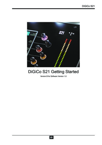
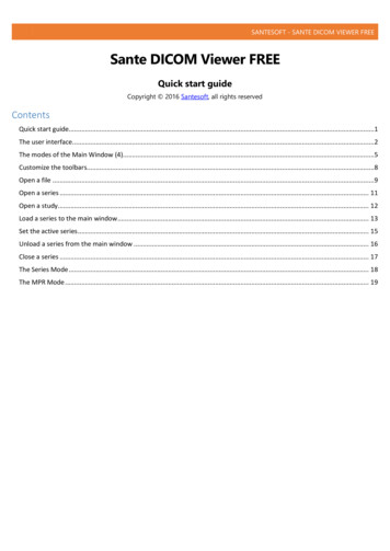
DiGiCo S-Series User Guide – Issue J1.1 The Console1.1 The ConsoleThe DiGiCo S21 and S31 consoles each consist of a worksurface, an audio engine and a range of onboard inputs and outputs. They canbe connected using optional DiGiCo DMI Cards to a variety of DiGiCo racks and other audio input/output devices.The console worksurface consists of 2 (S21) or 3 (S31) sections that can be configured to control up to 48 mono or stereo input channels,10 VCAs, 16 mono or stereo busses plus a Master buss and a 10 Input x 8 Output Matrix.The left and right sections (and the middle section if using an S31) have 10 assignable faders and 10 sets of assignable on-screen channelcontrols, the right hand section also has a dedicated Master fader and mute, a Master/Solo meter, a set of 6 assignable encoder/switchesand worksurface navigation controlsThe console's buss architecture is dynamic and can support mono and stereo configurations.Multiple console setups can provide:Front of House and Monitoring with shared stage racks and gain tracking.S21 (above) and S31 (below)NOTE: The S21 and S31 offer the same channel counts, buss counts and processing as each other. The only difference between the twoconsoles is the number of worksurface sections and the placement of banks on a default session. In this manual, all screenshots aretaken from an S21 console. S31 and S21 sessions are interchangeable provided that the software version used on the console is notearlier than the software version that the session was created in. There is no backward compatibility of sessions.1
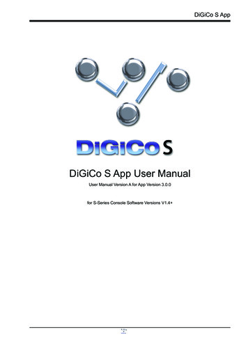
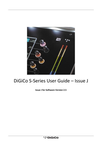
DiGiCo S-Series User Guide – Issue J1.2 Before You Start1.2 Before You StartThere are certain general operating principles and terms that should be understood before continuing to use this manual. Please readthis chapter carefully before proceeding.IMPORTANT NOTES:S-Series v2.5 software is not compatible with any sessions created in preliminary (pre v1.0) versions of software.It is compatible with all sessions created in v1.0 onwards.Please delete old sessions (pre 1.0) to avoid potential issues and create a "New" session in v2.5.The console power switch is situated on the rear panel.Please ensure that any required DiGiCo I/O racks are connected to the console DMI cards and powered on before starting the consoleitself to enable automatic discovery of the racks.If using the inbuilt UB MADI interface with a computer running MacOS Catalina, use the Core Audio driver and not the UB MADI driver.DMI cards are NOT "Hot swappable" so please ensure that the console is powered off before inserting or removing them.We recommend that the first snapshot is used as a "Setup" Snapshot where all of your "session wide" settings like routing, ControlGroup membership and Buss Modes (whether Busses are Groups or Auxes) are first stored.Because these types of setting can be changed with Snapshot recall, it is advisable to save them all into this first snapshot beforecreating any further Snapshots. In this way, the settings for all subsequent Snapshots will contain the same data and there should beless requirement to adjust the Safe settings in the channels.Assignable Encoder/Switches1.2.1 Worksurface LayoutMultiTouch ScreenMaster/Solo MetersAssignable Encoder/SwitchesHeadphone LevelSnapshot Previous/NextSolo & MuteMaster FaderChannel FadersSpill SetOverview Layer Up/DownRear PanelWord Clock I/OConsole EthernetDVI Screen OutputSEE NOTE BELOWGPI/OAES I/OUB MADI Connector12 Line Out24 Mic/Line InConsole USBDMI Slot 2DMI Slot 1IMPORTANT NOTE: The DVI Screen output will display a copy of the Master (right hand) screen but this must be connected to the HDMIinput of a suitable monitor using a standard DVI to HDMI adaptor (not supplied).IMPORTANT NOTE: The GPI/O functionality is not yet implemented in v2.5.2
DiGiCo S-Series User Guide – Issue J1.2 Before You Start1.2.2 Layers and BanksThe S-Series worksurface is divided into Layers and Banks. Each Layer contains 2 (S21) or 3 (S31) Banks of 10 channels, and the layerwhich is currently active on the control surface is selected using the layer up and down buttons next to the Master fader.The right hand screen is referred to as the Master Screen and this is where the various expanded views of elements such as EQ andDynamics are displayed.Pressing the white Overview button, located near the layer up and down buttons displays an on screen representation of all consolechannels and the active layer can also be selected by touching it on the screen in this mode. The specific channels which are containedwithin each Bank are defined in the Overview display.By default on an S21, the Input channels will be assigned to Layers 1 and 2 and 3 on the left and right sections of the console. The differentoutput channels will be assigned to Layer 3 and 4. Control Groups will be assigned to Layer 5.A default session on an S31 will assign the Control Groups, Auxes and Groups to Layers 1, 2 and 3 of the right hand section respectively.The Input channels and the Matrix channels will be assigned to Layers 1, 2 and 3 of the left hand section and the middle section.These bank assignments can be customised by the user and saved in a session at any time.1.2.3 Using the Control SurfaceThere are two main ways in which all of the functions of the S-Series are accessed:1.2.The touchscreen display, which can be controlled directly using a fingerThe physical encoders, switches and fadersA number of functions can be accessed in different ways, allowing users to operate the console using whichever interface they prefer.All of the physical controls on the console worksurface are described in full within the relevant section of the manual and many requireno further introduction.The right hand Master Screen has a DiGiCo logo icon at the top which is used to access the Main Menu.Main Menu3
DiGiCo S-Series User Guide – Issue J1.2 Before You Start1.2.4 The Selected ChannelOne of the channels in the Channel view is displayed with a highlighted background, indicating that it is currently the Selected Channel.This means that it has been assigned to the worksurface controls to the right of the screen as shown in the image below. To assign achannel, touch in the Output Block at the bottom of the onscreen Channel view.NOTE: All of the master and under screen rotaries are encoders and switches in one unit.Often, different functions can be accessed by a standard turn, a push turn and a push (switch).e.g. Standard turn Gain control & Push turn Trim controlSelected ChannelAssignable Encoder/SwitchesGain & Trim (Push Turn)HPFCompressor ThresholdGate ThresholdAux Pan (Stereo)Aux LevelOutput Block areaTouch here to select a channelNOTE: When the right hand screen is not displaying the Channel view (e.g. it is displaying an EQ view), the masterscreen worksurface rotaries will not be assigned to the Channel view controls but to the controls for the EQ or otherexpanded view instead.The block at the top of each Channel Strip displays information about the processing that has been applied to the channel. This boxdisplays the Gain, Trim and Delay that has been added to the channel. There are also a number of symbols that can be seen along theChannel Strip which represent settings on the channel.Their meanings are as follows:Insert AInsert BListening To Copied AudioPhantom powerInverse Input PolarityGain trackingPadDiGiTubeEQ Dyn SwapDynamic EQThe channel is assigned to at least one GroupThe channel is a member of at least one Control Group4
DiGiCo S-Series User Guide – Issue J1.2 Before You Start1.2.5 The Under Screen ControlsSelected ChannelBlue Pan - Default assignmentTouch and Hold in this rowAssigns HPF Freq and On/Offand highlights in MauveTouch and Hold in this rowAssigns Dynamics 2 Threshold and On/Offand highlights in YellowTouch and Hold in this rowAssigns Gain/Trim and highlights in RedTouch and Hold in this rowAssigns Dynamics 1 Threshold andOn/Off and highlights in GreenTouch and Hold any AUX rowAssigns Aux Send & On/OffTouch the selected channelin this row to return todefault Pan assignmentThere is a row of 10 encoder/switches immediately below each touchscreen (shown above) that refer to the channels with which theyare aligned.These controls give access to the channel pans in standard operation and the surrounding coloured LED rings are blue.Touching and holding on the rows of controls onscreen assign these encoders to different parameters, the screen row changes colourand the LED rings change to a similar colour.In the above example the Gain/Trim row at the top of the Channel View has been touched, the row is highlighted in red and the underscreen controls are assigned to the Gain/Trim function.Other possible assignments are:HPF Frequency & On/Off - Row and LED ring highlighted in MauveDynamics 1 Threshold & On/Off - Row and LED ring highlighted in GreenDynamics 2 Threshold & On/Off - Row and LED ring highlighted in YellowSelected Aux row Send level & On/Off - Row and LED ring highlighted in PurpleAMM Weightings - Row and LED ring highlighted in Pale Green5
DiGiCo S-Series User Guide – Issue J1.3 The Expanded Views1.3 The Expanded Views1.3.1 Display Expanded ViewsA single touch (rather than a touch and hold) will open a number of different expanded views according to where the touch is made.Open Channel Setup viewOpen EQ ViewOpen Dynamics 1 ViewOpen Dynamics 2 ViewTouch any Aux Send to select the channel and assignthe selected Aux Send to the 6th Master Rotary & AuxPan to the 5th (with Aux To Faders option OFF)Swipe vertically to display more AuxesTouch here to select a channelThe image above shows the various touch areas in the Channel view and the expanded view will be displayed on the Master screen.NOTE: When an expanded view is already open, selecting a different channel by touching the Output block area atthe bottom of the screen will change the expanded view to display the newly selected channel.If an expanded view is already open and a different expanded view is selected, the last view selected will bedisplayed on the Master screen with the previously expanded view behind it.Any combination of expanded views can be "layered" in this way.The Close All button on the Master screen can be touched at any time to close all active expanded views.The Close button on the Master screen can be touched at any time to close the currently active expanded view and display the viewbeneath it.6
DiGiCo S-Series User Guide – Issue J1.3 The Expanded Views1.3.2 Channel Setup ViewTouching the input block at the top of the channel opens the Channel Setup view.Each column represents a section of the channel processing strip and contains blocks which can be selected by touching them.On screen arrows indicate the signal path from one section of processing to the next.Once a block is selected, the display changes accordingly and the parameters available in that section are assigned to the worksurface.Master Rotaries to the right of the screen.Note that touching the Filter block or the EQ block will both display the EQ view but with different bands selected.NOTE: When any expanded view is open on the Master screen, the Master Rotaries no longer have their standarddefault assignment and are instead assigned to the parameters in the expanded view which is currently displayed.Channel Mono/Stereo SwitchAdd To Spill SetOpen Safes ViewCopy Channel SettingsPresetsGangingColumn TitleLabelChannel NameSelect Input SourceRecordingSend & ReturnFilters/Delay/TubesGain Tracking On/OffHPF On/OffLPFInsert AInsert BEQDyn 1Dyn 2EQ DYN SwapMaster Rotary AssignmentAuxesGroupsDirect OutDirect Out PositionSelect Solo AssignmentScroll ToSetup ViewStereo Balance& WidthDelay On/OffDelay TimeTube On/OffTube DriveScroll ToEQ ViewTube BiasHPF/LPF Frequency7
DiGiCo S-Series User Guide – Issue J1.3 The Expanded ViewsChannel Names can be changed by touching on the existing Channel Name to open the Rename View and then using the Left/Rightscroll buttons to move through channels without closing the Rename View.Touching the Star icon next to the channel name will add the selected channel to the Spill Set (see Spill Set section later in this document).The buttons in the top bar provide the following functions:Switching the channel from Mono to Stereo modeOpening the Safes View which allows channel parameters to be protected from Snapshot RecallOpening the Channel Copy viewOpening the Presets view where a preset can either be saved or recalledOpening the Gang Setup viewChannel Delay, Tube, Filter and Stereo Width/Balance (Stereo Input channels only) settings are adjusted by touching in the InputProcessing column. This will open an Input Processing View.At the bottom of the input processing column is a switch to turn Gain Tracking On/Off for the channel.Touch the Equaliser button at the bottom left of the screen to switch to the EQ view for the currently selected channel.To select an Input Route touch the block below the Source label and the Input routing view will open.To select an Output Route touch the Direct Output block in the Outputs column and the output routing view will open.The Direct Out Position can be set to either pre-mute, pre-fader or post-fader.To assign the channel to a Group buss touch the Group Assigns button in the Outputs column.To view and adjust Aux Send Options for the channel touch the relevant Aux Sends button in the Outputs column.To select which Solo Busses the channel is assigned to touch the Solo 1, Solo 2 or both Solo 1&2 buttons at the bottom of the Outputscolumn.The default processing order of EQ Dynamics can be swapped to Dynamics EQ independently in any channel using the EQ Dyn Swapbutton at the bottom of the Channel processing column.Direct out PositionThe direct out send can be sent from one of three positions: pre-mute, pre-fader or post-fader (default) on a per input channel basis.This does not affect the send position to any buses.The default send position is post-fader and the selected position is not saved in presets.The position is included in the direct out section of the channel safe.NOTE: DiGiTubes are limited to 21 per session.8
DiGiCo S-Series User Guide – Issue J1.3 The Expanded Views1.3.3 Copy ChannelMultiple settings can be copied from one channel to single or multiple other channels using the Copy Channel button in the Channelsetup view.Open the Channel Setup view for the required source channel by touching the top of its channel strip.Touch the Copy Channel button in the top bar.Touch to select or deselect the parameters that you wish to copy - selected blocks will be highlighted in green.To select/deselect all of the channel parameters that can be copied touch the Full Copy button in the top bar.Touch the Copy button in the bottom right of the screen.Select the Destination channel(s) by touching them on screen - they will have a white outline.Touch the OK button in the bottom right of the screen.Copy Channel FunctionSource ChannelSetup ViewFull CopyOptionGreen (Selected)parameters willbe pyNOTE: Channel Name is not included in the Full Copy selection but can be selected separately if desired.NOTE: Insert and Output routes cannot be copied as they could cause conflicts with existing routes.Not all parameter types exist for all channel types so some options might be unavailablee.g. Buss mode on an input channel.9
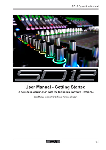
DiGiCo S-Series User Guide – Issue J1.3 The Expanded Views1.3.4 PresetsSelect the preset toupdateCreate a newpresetSelect thescopes to load– SocketPropertiesincludes gain,pad, phantompower and AESSRCSelect the group orpreset to renameSelect the preset(s) todeletePress the group nameto expand and collapseGroups andpresets listedin alphabeticalorderLoad, updateor delete theselectedpreset(s)Presets can be used on Input, Group, Aux, Matrix, CG and Master channels. Preset scopes are used to select which parameters are loadedinto the selected channel.New presets can be made by opening the presets view in the desired channel’s setup, EQ, dynamics 1 or dynamics 2 view. In this view,press New then enter the preset name and optionally, a group, before confirming. All parameters for that channel are saved into a preset.The view in which the preset was created will determine the preset icon.Presets are updated and deleted by selecting one of these functions in the top of the presets view, selecting the presets to be updatedor deleted, then confirming by pressing the Update or Delete confirm at the bottom right of the view. To rename a preset or group,select Rename then touch on the preset or group which will bring up a rename dialogue.10
DiGiCo S-Series User Guide – Issue J1.3 The Expanded Views1.3.5 Channel GangingAny channel can be ganged (linked) to one or more other channels (up to a maximum of 10 channels) so that changes made on one willalso be made to other members of the gang. This excludes Control Group and Solo channel types.All level parameters that are measured in dBs (e.g. faders) will change relatively so moving a fader on one member of the gang by 3dBwill
DiGiCo S-Series User Guide - Issue J 1.1 The Console 1 1.1 The Console The DiGiCo S21 and S31 consoles each consist of a worksurface, an audio engine and a range of onboard inputs and outputs. They can be connected using optional DiGiCo DMI Cards to a variety of DiGiCo racks and other audio input/output devices.