Transcription
2General DesignProcedure 2-13 Find or Revise theCenter of Gravity of a Vessel . 90Procedure 2-14: Minimum Design MetalTemperature (MDMT). 90Procedure 2-15: Buckling of Thin WallCylindrical Shells . 95Procedure 2-16: Optimum VesselProportions. 96Procedure 2-17: Estimating Weights of Vesselsand Vessel Components . 102Procedure 2-18: Design of Jacketed Vessels. 124Procedure 2-19: Forming Strains/FiberElongation. 134References. 138Procedure 2-1: General Vessel Formulas . 38Procedure 2-2: External Pressure Design. 42Procedure 2-3: Properties of Stiffening Rings . 51Procedure 2-4: Code Case 2286. 54Procedure 2-5: Design of Cones . 58Procedure 2-6: Design of ToriconicalTransitions . 67Procedure 2-7: Stresses in Heads Dueto Internal Pressure . 70Procedure 2-8: Design of Intermediate Heads . 74Procedure 2-9: Design of Flat Heads . 76Procedure 2-10: Design of Large Openingsin Flat Heads . 81Procedure 2-11: Calculate MAP, MAWP, andTest Pressures . 83Procedure 2-12: Nozzle Reinforcement. 8537
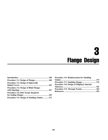
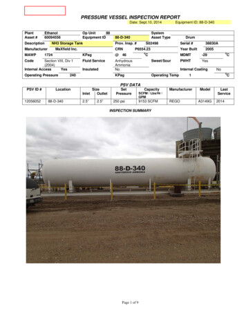
38Pressure Vessel Design ManualProcedure 2-1: General Vessel Formulas [1,2]NotationPDi, DoSELRi, RoK, MsxsfRmt¼¼¼¼¼¼¼¼¼¼¼internal pressure, psiinside/outside diameter, in.allowable or calculated stress, psijoint efficiencycrown radius, in.inside/outside radius, in.coefficients (See Note 3)longitudinal stress, psicircumferential stress, psimean radius of shell, in.thickness or thickness required of shell, head,or cone, in.r ¼ knuckle radius, in.Notes1. Formulas are valid for:a. Pressures 3,000 psi.b. Cylindrical shells where t 0.5 Ri or P 0.385SE. For thicker shells see Reference 1, Para. 1–2.c. Spherical shells and hemispherical heads wheret 0.356 Ri or P 0.665 SE. For thicker shellssee Reference 1, Para. 1–3.2. All ellipsoidal and torispherical heads havinga minimum specified tensile strength greater than80,000 psi shall be designed using S ¼ 20,000 psi atambient temperature and reduced by the ratio ofthe allowable stresses at design temperature andambient temperature where required.Figure 2-1. General configuration and dimensional datafor vessel shells and heads.3. Formulas for factors: 2 DK ¼ 0:167 2 þ2hrffiffiffi!LM ¼ 0:25 3 þr
Table 2-1General vessel formulasThickness, tPartStress FormulaPressure, PI.D.O.D.I.D.Stress, SO.D.ShellI.D.O.D.Longitudinal[1, Section UG-27(c)(2)]sx ¼PRm0:2tPRi2SE þ 0:4PPRo2SE þ 1:4P2SEtRi 0:4t2SEtRo 1:4tPðRi 0:4tÞ2EtPðRo 1:4tÞ2EtCircumferential[1, Section UG-27(c)(1);Section 1-1 (a)(1)]Headssf ¼PRmtPRiSE 0:6PPRoSE þ 0:4PSEtRi þ 0:6tSEtRo 0:4tPðRi þ 0:6tÞEtPðRo 0:4tÞEtHemisphere[1, Section 1-1 (a)(2);Section UG-27(d)]Ellipsoidal[1, Section 1-4(c)]sx ¼ sf ¼PRi2SE 0:2PPRo2SE þ 0:8P2SEtRi þ 0:2t2SEtRo 0:8tPðRi þ 0:2tÞ2EtPðRo 0:8tÞ2EtSee Procedure 2-7PDi K2SE 0:2PPDo K2SE þ 2PðK 0:1Þ2SEtKDi þ 0:2t2SEtKDo 2tðK 0:1ÞSee Procedure2-72:1 S.E.[1, Section UG-32(d)]See Procedure 2-7PDi2SE 0:2PPDo2SE þ 1:8P2SEtDi þ 0:2t2SEtDo 1:8tSee Procedure2-7100%e6% Torispherical[1, Section UG-32(e)]See Procedure 2-70:885PLiSE 0:1P0:885PLoSE þ 0:8PSEt0:885Li þ 0:1tSEt0:885Lo 0:8tSee Procedure2-7Torispherical L/r 16.66[1, Section 1-4(d)]See Procedure 2-7PLi M2SE 0:2PPLo M2SE þ PðM 0:2Þ2SEtLi M þ 0:2t2SEtLo M tðM 0:2ÞSee Procedure2-7PRm2tConesx ¼PRm2tcosfPDi4cosfðSE þ 0:4PÞPDo4cosfðSE þ 1:4PÞ4SEtcosfDi 0:8tcosf4SEtcosfDo 2:8tcosfPðDi 0:8tcosfÞ4EtcosfPðDo 2:8tcosfÞ4EtcosfCircumferential[1, Section 1-4(e);Section UG-32(g)]sf ¼PRmtcosfPDi2cosfðSE 0:6PÞPDo2cosfðSE þ 0:4PÞ2SEtcosfDi þ 1:2tcosf2SEtcosfDo 0:8tcosfPðDi þ 1:2tcosfÞ2EtcosfPðDo 0:8tcosfÞ2EtcosfGeneral DesignLongitudinal39
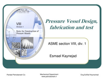
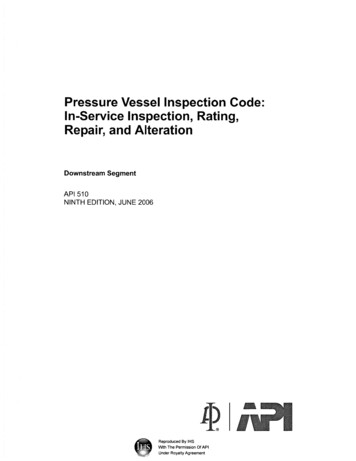
40Pressure Vessel Design ManualFigure 2-1a. Required shell thickness of cylindrical shell.
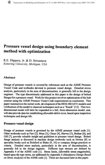
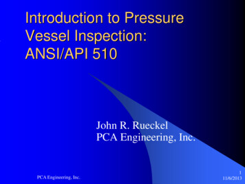
General DesignFigure 2-1a. (continued).41
42Pressure Vessel Design ManualProcedure 2-2: External Pressure DesignNotationA ¼ factor “A,” strain, from ASME Section II, PartD, Subpart 3, dimensionlessAs ¼ cross-sectional area of stiffener, in.2B ¼ factor “B,” allowable compressive stress, fromASME Section II, Part D, Subpart 3, psiD ¼ inside diameter of cylinder, in.Do ¼ outside diameter of cylinder, in.DL ¼ outside diameter of the large end of cone, in.Ds ¼ outside diameter of small end of cone, in.E ¼ modulus of elasticity, psiI ¼ actual moment of inertia of stiffener, in.4Is ¼ required moment of inertia of stiffener, in.4I0 s ¼ required moment of inertia of combined shellring cross section, in.4L ¼ for cylindersdthe design length for externalpressure, including 1/3 the depth of heads, in.For conesdthe design length for externalpressure (see Figures 2-1b and 2-1c), in.Le ¼ equivalent length of conical section, in.Ls ¼ length between stiffeners, in.LT–T ¼ length of straight portion of shell, tangent totangent, in.P ¼ design internal pressure, psiPa ¼ allowable external pressure, psiPx ¼ design external pressure, psiRo ¼ outside radius of spheres and hemispheres,crown radius of torispherical heads, in.t ¼ thickness of cylinder, head or conical section,in.te ¼ equivalent thickness of cone, in.a ¼ half apex angle of cone, degreesUnlike vessels which are designed for internal pressurealone, there is no single formula, or unique design, whichfits the external pressure condition. Instead, there is a rangeof options available to the designer which can satisfy thesolution of the design. The thickness of the cylinder is onlyone part of the design. Other factors which affect the designare the length of cylinder and the use, size, and spacing ofstiffening rings. Designing vessels for external pressure isan iterative procedure. First, a design is selected with all ofthe variables included, then the design is checked todetermine if it is adequate. If inadequate, the procedure isrepeated until an acceptable design is reached.Vessels subject to external pressure may fail at wellbelow the yield strength of the material. The geometry ofthe part is the critical factor rather than material strength.Failures can occur suddenly, by collapse of thecomponent.External pressure can be caused in pressure vessels bya variety of conditions and circumstances. The designpressure may be less than atmospheric due to condensinggas or steam. Often refineries and chemical plants designall of their vessels for some amount of external pressure,regardless of the intended service, to allow for steamcleaning and the effects of the condensing steam. Othervessels are in vacuum service by nature of venturi devicesor connection to a vacuum pump. Vacuums can be pulledinadvertently by failure to vent a vessel during draining, orfrom improperly sized vents.External pressure can also be created when vessels arejacketed or when components are within multichamberedvessels. Often these conditions can be many times greaterthan atmospheric pressure.When vessels are designed for both internal andexternal pressure, it is common practice to first determinethe shell thickness required for the internal pressurecondition, then check that thickness for the maximumallowable external pressure. If the design is not adequatethen a decision is made to either bump up the shellthickness to the next thickness of plate available, or addstiffening rings to reduce the “L” dimension. If the optionof adding stiffening rings is selected, then the spacing canbe determined to suit the vessel configuration.Neither increasing the shell thickness to remove stiffening rings nor using the thinnest shell with the maximumnumber of stiffeners is economical. The optimum solutionlies somewhere between these two extremes. Typically,the utilization of rings with a spacing of 2D for vesseldiameters up to about eight feet in diameter and a ringspacing of approximately “D” for diameters greater thaneight feet, provides an economical solution.The design of the stiffeners themselves is also a trial anderror procedure. The first trial will be quite close if the oldAPI-ASME formula is used. The formula is as follows:Is ¼0:16D3o Px LsEStiffeners should never be located over circumferentialweld seams. If properly spaced they may also double as
General Designinsulation support rings. Vacuum stiffeners, if combinedwith other stiffening rings, such as cone reinforcementrings or saddle stiffeners on horizontal vessels, must bedesigned for the combined condition, not each independently. If at all possible, stiffeners should always clearshell nozzles. If unavoidable, special attention should begiven to the design of a boxed stiffener or connection tothe nozzle neck.dimension. If stiffening rings are to be utilized, thenproceed with the following steps.Step 9: Select a stiffener spacing based on the maximumlength of unstiffened shell (see Table 2-1a). The stiffener spacing can vary up to the maximum valueallowable for the assumed thickness. Determine thenumber of stiffeners necessary and the corresponding“L” dimension.Step 10: Assume an approximate ring size based on thefollowing equation:Design Procedure For Cylindrical ShellsStep 1: Assume a thickness if one is not alreadydetermined.Step 2: Calculate dimensions “L” and “D.” Dimension “L”should include one-third the depth of the heads. Theoverall length of cylinder would be as follows for thevarious head types:W/(2) hemi-headsW/(2) 2:1 S.E. headsW/(2) 100% e 6% headsL ¼ LT T þ 0:333DL ¼ LT T þ 0:1666DL ¼ LT T þ 0:112DStep 3: Calculate L/Do and Do/t ratiosStep 4: Determine Factor “A” from ASME Code, SectionII, Part D, Subpart 3, Fig G: Geometric Chart forComponents Under External or Compressive Loadings(see Figure 2-1e).Step 5: Using Factor “A” determined in step 4, enter theapplicable material chart from ASME Code, Section II,Part D, Subpart 3 at the appropriate temperature anddetermine Factor “B.”Step 6: If Factor “A” falls to the left of the material line,then utilize the following equation to determine theallowable external pressure:2AEPa ¼3ðDo tÞStep 7: For values of “A” falling on the material line of theapplicable material chart, the allowable external pressure should be computed as follows:4BPa ¼3ðDo tÞStep 8: If the computed allowable external pressure is lessthan the design external pressure, then a decision mustbe made on how to proceed. Either (a) select a newthickness and start the procedure from the beginning or(b) elect to use stiffening rings to reduce the “L”43I ¼0:16D3o Px LsEStep 11: Compute Factor “B” from the following equationutilizing the area of the ring selected:B ¼0:75PDot þ As LsStep 12: Utilizing Factor “B” computed in step 11, find thecorresponding “A” Factor from the applicable materialcurve.Step 13: Determine the required moment of inertia fromthe following equation. Note that Factor “A” is the onefound in step 12. 2 Do Ls t þ As Ls AIs ¼14Step 14: Compare the required moment of inertia, I, withthe actual moment of inertia of the selected member. Ifthe actual exceeds that which is required, the design isacceptable but may not be optimum. The optimizationprocess is an iterative process in which a new memberis selected, and steps 11 through 13 are repeated untilthe required size and actual size are approximatelyequal.Notes1. For conical sections where a 22.5 degrees, designthe cone as a cylinder where Do ¼ DL and length isequal to L.2. If a vessel is designed for less than 15 psi, andthe external pressure condition is not going to bestamped on the nameplate, the vessel does nothave to be designed for the external pressurecondition.
44Pressure Vessel Design ManualFigure 2-1b. External pressure cones 22 1/2 a 60 .For Case B, Le ¼ LFor Cases A, C, D, E: DsLe ¼ 0:5 1 þDLte ¼ t cos aDL te ¼Le DL ¼
General Design45Figure 2-1c. Combined shell/cone design for stiffened shells.Design stiffener for large end of cone as cylinderwhere:Design stiffener for small end of cone as cylinderwhere:Do ¼ DLDo ¼ D st ¼ tLt ¼ tsL1 L2Ls ¼þ22 L3 L2DsLs ¼þ1þ22DLFigure 2-1d. External pressure spheres and heads.
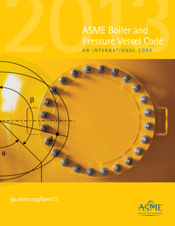
46Pressure Vessel Design ManualFigure 2-1e. Geometric chart for components under external or compressive loadings (for all materials). (Reprinted bypermission from the ASME Code, Section VIII, Div. 1.)
General DesignDesign Procedure For Spheres and HeadsStep 1: Assume a thickness and calculate Factor “A.”0:125tA ¼Ro47Step 2: Find Factor “B” from applicable material chart.B ¼Step 3: Compute Pa.Figure 2-1f. Chart for determining shell thickness of components under external pressure when constructed of carbonor low-alloy steels (specified minimum yield strength 24,000psi to, but not including, 30,000psi). (Reprinted bypermission from the ASME Code, Section VIII, Div. 1.)Figure 2-1g. Chart for determining shell thickness of components under external pressure when constructed of carbonor low-alloy steels (specified minimum yield strength 30,000 psi and over except materials within this range where otherspecific charts are referenced) and type 405 and type 410 stainless steels. (Reprinted by permission from the ASMECode, Section VIII, Div. 1.)
48Pressure Vessel Design ManualA to left of material line Pa ¼Notes0:0625EðRo tÞ2A to right of material line Pa ¼1. As an alternative, the thickness required for 2:1 S.E.heads for external pressure may be computed fromthe formula for internal pressure where P ¼ 1.67 Pxand E ¼ 1.0.BtRoTable 2-1aMaximum length of unstiffened shellsThickness (in.)102108114120126132138144150156162 145 16 96389 165811 119996189458N408N36968633662
Vessels subject to external pressure may fail at well below the yield strength of the material. The geometry of the part is the critical factor rather than material strength. Failures can occur suddenly, by collapse of the component. External pressure can be caused in pressure vessels by a variety of conditions and circumstances. The designFile Size: 1MBPage Count: 34Explore furtherRead Download Pressure Vessel Design Manual PDF – PDF .bibleandbookcenter.comPressure Vessel Design Manual 3rd Ed. - W E B A E R Owebaero.netPressure Vessel Design Calculations Handbook Engineers .www.engineersedge.comDesign of pressure vessel using ASME codes and a .www.irjet.netRecommended to you based on what's popular Feedback