Transcription
Pressure Vessel Design,fabrication and testASME section VIII, div. 1Esmael KaynejadPardad Petrodanesh CoMechanical Departmentwww.petrodanesh.ir1 KeynezhadEng.Esmail
Pardad Petrodanesh CoMechanical Departmentwww.petrodanesh.ir2Eng.Esmail Keynezhad
Pardad Petrodanesh CoMechanical Departmentwww.petrodanesh.ir3Eng.Esmail Keynezhad
Pardad Petrodanesh CoMechanical Departmentwww.petrodanesh.ir4Eng.Esmail Keynezhad
Pardad Petrodanesh CoMechanical Departmentwww.petrodanesh.ir5Eng.Esmail Keynezhad
Pardad Petrodanesh CoMechanical Departmentwww.petrodanesh.ir6Eng.Esmail Keynezhad
Pardad Petrodanesh CoMechanical Departmentwww.petrodanesh.ir7Eng.Esmail Keynezhad
Pardad Petrodanesh CoMechanical Departmentwww.petrodanesh.ir8Eng.Esmail Keynezhad
Pardad Petrodanesh CoMechanical Departmentwww.petrodanesh.ir9Eng.Esmail Keynezhad
Structure of vessels:Pardad Petrodanesh CoMechanical Departmentwww.petrodanesh.irEng.Esmail Keynezhad
ASME Section VIII Division 1Content Subsection AGeneral Requirements Subsection BRequirements Pertaining to Methods of Fabricationof Pressure Vessels Subsection CRequirements Pertaining to Classes of MaterialsPardad Petrodanesh CoMechanical Departmentwww.petrodanesh.ir11Eng.Esmail Keynezhad
Subsection AASME VIII Div.1General Requirements for AllMethods of Construction and AllMaterialsPardad Petrodanesh CoMechanical Departmentwww.petrodanesh.ir12Eng.Esmail Keynezhad
Part UGScopeMaterialsDesignOpenings and ReinforcementsBraced and Stayed SurfacesLigamentsFabricationInspection and TestsMarking and ReportsPressure Relief DevicesPardad Petrodanesh CoMechanical Departmentwww.petrodanesh.ir13Eng.Esmail Keynezhad
ASME Section VIII Div. 1 Part UGMaterials UG-1 scopeUG-4 generalUG-5 PlateUG-6 ForgingsUG-7 CastingsUG-8 Pipe and TubesUG-9 Welding MaterialsUG-10 Material Identified With or Produced to a Specification NotPermitted by This Division, and Material Not Fully IdentifiedUG-11 Prefabricated or Preformed Pressure PartsUG-12 Bolts and StudsUG-13 Nuts and WashersUG-14 Rods and BarsUG-15 Product SpecificationPardad Petrodanesh CoMechanical Departmentwww.petrodanesh.ir14Eng.Esmail Keynezhad
ASME Section VIII Div. 1 Part UGDesign UG-16 GeneralUG- 17 Methods of Fabrication in CombinationUG-18 Materials in CombinationUG-19 Special ConstructionsUG-20 Design TemperatureUG-21 Design PressureUG-22 LoadingsUG-23 Maximum Allowable Stress ValuesUG-24 CastingsUG-25 CorrosionUG-26 LiningsPardad Petrodanesh CoMechanical Departmentwww.petrodanesh.ir15Eng.Esmail Keynezhad
ASME Section VIII Div. 1 Part UGDesign(cont.) UG-27 Thickness of Shells Under Internal Pressure UG-28 Thickness of Shells and Tubes Under External Pressure UG-29 Stiffening Rings for Cylindrical Shells Under ExternalPressure UG-30 Attachment of Stiffening Rings UG-31 Tubes, and Pipe When Used as Tubes or Shells UG-32 Formed Heads, and Sections, Pressure on ConcaveSide UG-33 Formed Heads, Pressure on Convex Side UG-34 Unstayed Flat Heads and Covers UG-35 Other Types of ClosuresPardad Petrodanesh CoMechanical Departmentwww.petrodanesh.ir16Eng.Esmail Keynezhad
UG-23 MAXIMUM ALLOWABLE STRESSVALUESThe maximum allowable stress value is the maximumunit stress permitted in a given material used in avessel constructed under these rules. The maximumallowable tensile stress values permitted fordifferent materials are given in Subpart 1 of SectionII, Part D.Pardad Petrodanesh CoMechanical Departmentwww.petrodanesh.ir17Eng.Esmail Keynezhad
Pardad Petrodanesh CoMechanical Departmentwww.petrodanesh.ir18Eng.Esmail Keynezhad
Pardad Petrodanesh CoMechanical Departmentwww.petrodanesh.ir19Eng.Esmail Keynezhad
Pardad Petrodanesh CoMechanical Departmentwww.petrodanesh.ir20Eng.Esmail Keynezhad
Openings and Reinforcements UG-36 Openings in Pressure Vessels UG-37 Reinforcement Required for Openings in Shells andFormed Heads UG-38 Flued Openings in Shells and Formed Heads UG-39 Reinforcement Required for Openings in Flat Heads UG-40 Limits of Reinforcement UG-41 Strength of Reinforcement UG-42 Reinforcement of Multiple Openings UG-43 Methods of Attachment of Pipe and Nozzle Necks toVessel Walls UG-44 Flanges and Pipe Fittings UG-45 Nozzle Neck ThicknessMechanical Department21Pardad Petrodanesh CoEng.Esmail Keynezhadwww.petrodanesh.ir UG-46 Inspection Openings
Braced and Stayed Surfaces UG-47 Braced and Stayed SurfacesUG-48 StayboltsUG-49 Location of StayboltsUG-50 Dimensions of StayboltsLigamentsUG-53 LigamentsUG-54 SupportsUG-55 Lugs for Platforms, Ladders, and Other Attachments toVessel WallsPardad Petrodanesh CoMechanical Departmentwww.petrodanesh.ir22Eng.Esmail Keynezhad
ASME Section VIII Div. 1 Part UGFabrication UG-75 GeneralUG-76 Cutting Plates and Other StockUG-77 Material Identification (See UG-85)UG-78 Repair of Defects in MaterialsUG-79 Forming Shell Sections and HeadsUG-80 Permissible Out-of-Roundness of Cylindrical, Conical,and Spherical ShellsUG-81 Tolerance for Formed HeadsUG-82 Lugs and Fitting AttachmentsUG-83 Holes for Screw StaysUG-84 Charpy Impact TestsUG-85 Heat TreatmentPardad Petrodanesh CoMechanical Departmentwww.petrodanesh.ir23Eng.Esmail Keynezhad
ASME Section VIII Div. 1 Part UGInspectionand Tests UG-90 GeneralUG-91 The InspectorUG-92 Access for InspectorUG-93 Inspection of MaterialsUG-94 Marking on MaterialsUG-95 Examination of Surfaces During FabricationUG-96 Dimensional Check of Component PartsUG-97 Inspection During FabricationUG-98 Maximum Allowable Working PressureUG-99 Standard Hydrostatic TestUG-100 Pneumatic Test (See UW-50)UG-101 Proof Tests to Establish Maximum Allowable Working PressureUG-102 Test GagesUG-103 Nondestructive TestingPardad Petrodanesh CoMechanical Departmentwww.petrodanesh.ir24Eng.Esmail Keynezhad
Standard’s terminology Inspection, examination, and testing areactivities carried out to ensure that systemmeet the minimum requirements of thestandard or code and the engineering design. inspection and examination do not mean thesame thing.Pardad Petrodanesh CoMechanical Departmentwww.petrodanesh.ir25Eng.Esmail Keynezhad
ASME B31.3 CodePardad Petrodanesh CoMechanical Departmentwww.petrodanesh.ir26Eng.Esmail Keynezhad
Pardad Petrodanesh CoMechanical Departmentwww.petrodanesh.ir27Eng.Esmail Keynezhad
Pardad Petrodanesh CoMechanical Departmentwww.petrodanesh.ir28Eng.Esmail Keynezhad
Pardad Petrodanesh CoMechanical Departmentwww.petrodanesh.ir29Eng.Esmail Keynezhad
APPENDIX 10 of Section VIIIQUALITY CONTROL SYSTEM 10-1 GENERAL10-2 OUTLINE OF FEATURES TO BEINCLUDED IN THE WRITTENDESCRIPTION OF THE QUALITYCONTROL SYSTEM10-3 AUTHORITY ANDRESPONSIBILITY10-4 ORGANIZATION10-5 DRAWINGS, DESIGNCALCULATIONS, AND SPECIFICATIONCONTROL10-6 MATERIAL CONTROL10-7EXAMINATION AND INSPECTIONPROGRAM10-8CORRECTION OFNONCONFORMITIES 10-9 WELDING10-10 NONDESTRUCTIVEEXAMINATION10-11 HEAT TREATMENT10-12 CALIBRATION OFMEASUREMENT AND TESTEQUIPMENT10-13 RECORDS RETENTION10-14 SAMPLE FORMS10-15 INSPECTION OF VESSELS ANDVESSEL PARTS10-16 INSPECTION OF PRESSURERELIEF VALVESNote: These are like ISO9001 requirements innatureMechanical Department30Pardad Petrodanesh CoEng.Esmail Keynezhadwww.petrodanesh.ir
Subsection BASME VIII Div.1Requirements Pertaining toMethods of Fabrication ofPressure VesselsPardad Petrodanesh CoMechanical Departmentwww.petrodanesh.ir31Eng.Esmail Keynezhad
Subsection B Part UWRequirements for Pressure Vessels Fabricated by Welding Part UFRequirements for Pressure Vessels Fabricated by Forging Part UBRequirements for Pressure Vessels Fabricated by BrazingPardad Petrodanesh CoMechanical Departmentwww.petrodanesh.ir32Eng.Esmail Keynezhad
Part UWRequirements for Pressure Vessels Fabricated byWelding General Materials Design Fabrication Inspection and Tests Marking and Reports Pressure Relief DevicesPardad Petrodanesh CoMechanical Departmentwww.petrodanesh.ir33Eng.Esmail Keynezhad
Part UWGeneral UW-1 Scope UW-2 Service Restrictions UW-3 Welded Joint CategoryPardad Petrodanesh CoMechanical Departmentwww.petrodanesh.ir34Eng.Esmail Keynezhad
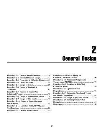
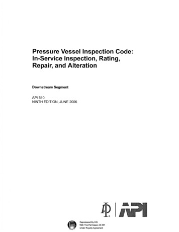
Heads Figurs show typical types of closure heads. Elliptical,hemispherical, and torispherical are the most commonly usedhead types. Note that all head types have a straight flange (sf)section, which simplifies welding the head to the adjacentcylindrical shell section. The elliptical and torispherical headshave an indicated head depth (h), which is measured from thestraight flange to the maximum point of curvature on theinside surface.Pardad Petrodanesh CoMechanical Departmentwww.petrodanesh.ir35Eng.Esmail Keynezhad
Pardad Petrodanesh CoMechanical Departmentwww.petrodanesh.ir36Eng.Esmail Keynezhad
Pardad Petrodanesh CoMechanical Departmentwww.petrodanesh.ir37Eng.Esmail Keynezhad
Pardad Petrodanesh CoMechanical Departmentwww.petrodanesh.ir38Eng.Esmail Keynezhad
Pardad Petrodanesh CoMechanical Departmentwww.petrodanesh.ir39Eng.Esmail Keynezhad
Pardad Petrodanesh CoMechanical Departmentwww.petrodanesh.ir40Eng.Esmail Keynezhad
Stiffener ringPardad Petrodanesh CoMechanical Departmentwww.petrodanesh.ir41Eng.Esmail Keynezhad
Pardad Petrodanesh CoMechanical Departmentwww.petrodanesh.ir42Eng.Esmail Keynezhad
Pardad Petrodanesh CoMechanical Departmentwww.petrodanesh.ir43Eng.Esmail Keynezhad
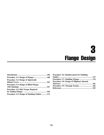
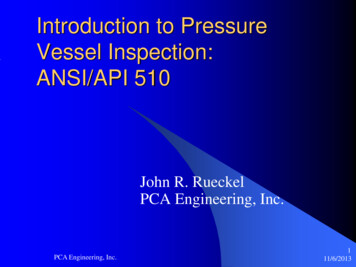
FIG. UG-30 SOME ACCEPTABLE METHODS OF ATTACHINGSTIFFENING RINGSPardad Petrodanesh CoMechanical Departmentwww.petrodanesh.ir44Eng.Esmail Keynezhad
Pardad Petrodanesh CoMechanical Departmentwww.petrodanesh.ir45Eng.Esmail Keynezhad
Part UW-Design UW-8 GeneralUW-9 Design of Welded JointsUW-10 Postweld Heat TreatmentUW-11 Radiographic and Ultrasonic ExaminationUW-12 Joint EfficienciesUW-13 Attachment DetailsUW-14 Openings in or Adjacent to WeldsUW-15 Welded ConnectionsUW-16 Minimum Requirements for Attachment Welds atOpenings UW-17 Plug WeldsUW-18 Fillet WeldsUW-19 Welded Stayed ConstructionUW-20 Tube-to-Tubesheet WeldsUW-21 Flange to NozzleNeck WeldsMechanical Department46Eng.Esmail KeynezhadPardad Petrodanesh Cowww.petrodanesh.ir
UW-9 DESIGN OF WELDED JOINTS(a)Permissible Types.(b)Welding Grooves.(c)Tapered Transitions.(d)Vessels made up of two or more coursesStaggering of longitudinal joints(e) Lap Joints.(f) Welded Joints Subject to Bending Stresses(g) Minimum Weld Sizes.Pardad Petrodanesh CoMechanical Departmentwww.petrodanesh.ir47Eng.Esmail Keynezhad
Fabrication UW-26 GeneralUW-27 Welding ProcessesUW-28 Qualification of Welding ProcedureUW-29 Tests of Welders and Welding OperatorsUW-30 Lowest Permissible Temperatures for WeldingUW-31 Cutting, Fitting, and AlignmentUW-32 Cleaning of Surfaces to Be WeldedUW-33 Alignment ToleranceUW-34 Spin-HolesUW-35 Finished Longitudinal and Circumferential JointsUW-36 Fillet WeldsUW-37 Miscellaneous Welding RequirementsUW-38 Repair of Weld DefectsUW-39 PeeningUW-40 Procedures for Postweld Heat TreatmentUW-41 Sectioning of Welded JointsUW-42 Surface Weld Metal Buildup .Pardad Petrodanesh CoMechanical Departmentwww.petrodanesh.ir48Eng.Esmail Keynezhad
Subsection CASME VIII Div.1Requirements Pertaining toClasses of MaterialsPardad Petrodanesh CoMechanical Departmentwww.petrodanesh.ir49Eng.Esmail Keynezhad
Subsection C of ASME VIII Div.1 Part UCSRequirements for Pressure Vessels ConstructedCarbon and Low Alloy Steelsof Part UNFRequirements for Pressure Vessels Constructed ofNonferrous Materials Part UHARequirements for Pressure Vessels Constructed of HighAlloy SteelPardad Petrodanesh CoMechanical Departmentwww.petrodanesh.ir50Eng.Esmail Keynezhad
Subsection C of ASME VIII Div.1Requirements Pertaining toClasses of Materials. Part UCIRequirements for Pressure Vessels Constructed of Cast Iron Part UCLRequirements for Welded Pressure Vessels Constructed ofMaterial With Corrosion Resistant Integral Cladding, WeldMetal Overlay Cladding, or With Applied Linings Part UCDRequirements for Pressure Vessels Constructed of CastDuctile IronPardad Petrodanesh CoMechanical Departmentwww.petrodanesh.ir51Eng.Esmail Keynezhad
Subsection CCont. Part UHTRequirements for Pressure Vessels Constructed of FerriticSteels With Tensile Properties Enhanced by Heat Treatment Part ULWRequirements for Pressure Vessels Fabricated by LayeredConstruction Part ULTAlternative Rules for Pressure Vessels Constructed ofMaterials Having Higher Allowable Stresses at LowTemperaturePardad Petrodanesh CoMechanical Departmentwww.petrodanesh.ir52Eng.Esmail Keynezhad
Part UCSRequirements for Pressure Vessels Constructed ofCarbon and Low Alloy SteelsPardad Petrodanesh CoMechanical Departmentwww.petrodanesh.ir53Eng.Esmail Keynezhad
Two important issues for carbon andlow alloy steels: Post weld heat treatment Impact testPardad Petrodanesh CoMechanical Departmentwww.petrodanesh.ir54Eng.Esmail Keynezhad
Temperatures to Consider Minimum Design Metal Temperature (MDMT) Lowest temperature at which component hasadequate fracture toughnessPardad Petrodanesh CoMechanical Departmentwww.petrodanesh.ir55Eng.Esmail Keynezhad
PWHT(stress relieving at around 600 centigrade)Pardad Petrodanesh CoMechanical Departmentwww.petrodanesh.ir56Eng.Esmail Keynezhad
Postweld heat treatment is mandatory underthe following conditions: (a) for welded joints over 11 2 in. (38 mm)nominal thickness; b) for welded joints over 11 4 in. (32 mm)nominal thickness through 11 2 in. (38 mm)nominal thickness unless preheat is applied ata minimum temperature of 200 F (95 C)during welding;Pardad Petrodanesh CoMechanical Departmentwww.petrodanesh.ir57Eng.Esmail Keynezhad
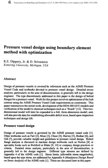
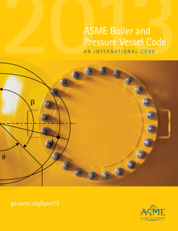
TABLE UCS-56POSTWELD HEAT TREATMENT IS REQUIRED ASTHE THICKNESS OR ALLOYING ELEMNTSINCREASEPardad Petrodanesh CoMechanical Departmentwww.petrodanesh.ir58Eng.Esmail Keynezhad
Pardad Petrodanesh CoMechanical Departmentwww.petro
ASME Section VIII Div. 1 Part UG Design UG-16 General UG- 17 Methods of Fabrication in Combination UG-18 Materials in Combination UG-19 Special Constructions UG-20 Design Temperature UG-21 Design Pressure UG-22 Loadings UG-23 Maximum Allowable Stress Values UG-24 Castings UG-25 Corrosion UG-26 Linings 15