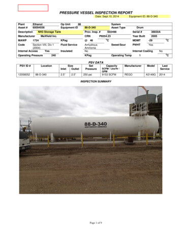
Transcription
3Flange DesignIntroduction . 140Procedure 3-1: Design of Flanges . 148Procedure 3-2: Design of SphericallyDished Covers . 165Procedure 3-3: Design of Blind Flangeswith Openings . 167Procedure 3-4: Bolt Torque Requiredfor Sealing Flanges . 169Procedure 3-5: Design of Studding Outlets . 172Procedure 3-6: Reinforcement for StuddingOutlets . 175Procedure 3-7: Studding Flanges . 176Procedure 3-8: Design of Elliptical, InternalManways . 181Procedure 3-9: Through Nozzles . 182References . 183139
140Pressure Vessel Design ManualIntroductionStandard flanges should be used wherever possible.The cost of designing and fabricating a custom flange isexpensive and should be a last resort. If a custom flange isrequired, and there is no alternative, then the proceduresincluded in this chapter can be utilized for designinga custom flange. The ASME Code accepts the standardpressure-temperature ratings of ASME B16.5 for flanges,classes 150 to 2500, ½” to 24”. For larger diameter flangesuse ASME B16.47.Flange Standards1. ASME/ANSI B16.5 (1/2” to 24” Class 150 to2500)2. ASME/ANSI B16.47 Series A: Replaced the Old API 605 (26” to 60”,Class 75 to Class 900) Series B: Based on MSS SP 44 Steel Pipelineflanges designed to ASME Section VIII Largeflanges (26” to 60”, Class 150 to Class 900)3. TEMA Flanges, Class R4. ASME/ANSI B16.1 Cast Iron Pipe Flanges5. ASME/ANSI B16.24 Bronze Flanges and FlangedFittings6. AWWA C207 Steel Pipe Flanges for Water WorksServices7. BS 3293 British Standards – Specification forCarbon Steel Pipe Flanges (over 24” nominal size)8. API Specification 6A (2,000 to 20,000 psi forwellhead equipment)9. MSS SP-51 Corrosion Resistant Cast Flanges andFlanged Fittings10. MSS SP-65 High Pressure Chemical Industry FlangesFlange DesignIn general, special designs as outlined in this procedureare done for large or high-pressure designs. Flanges in thiscategory will be governed by one of two conditions:1. Gasket seating force, Wm22. Hydrostatic end force, HFor high-pressure flanges, typically the hydrostatic endforce, H, will govern. For low-pressure flanges, the gasketseating force will govern. Therefore the strategy forapproaching the design of these flanges will vary. Thestrategy is as follows: For low-pressure flangesa. Minimize the gasket width to reduce the forcenecessary to seat the gasket.b. Use a larger number of smaller diameter bolts tominimize the bolt circle diameter and thus reducethe moment arm which governs the flangethickness.c. Utilize hubless flanges (either lap joint or plateflanges) to minimize the cost of forgings. For high-pressure flangesHigh-pressure flanges require a large bolt area tocounteract the large hydrostatic end force. Large bolts,in turn, increase the bolt circle with a correspondingincrease in the moment arm. Thicker flanges and largehubs are necessary to distribute the bolt loads. Seeka balance between the quantity and size of bolts, boltspacing, and bolt circle diameter.Design StrategyStep 1: Determine the number and size of bolts required.As a rule of thumb, start with a number of bolts equalto the nominal size of the bore in inches, rounded tothe nearest multiple of four. First, calculate Wm1 orWm2. Am is equal to the larger of Wm1 or Wm2 dividedby Sa. The quantity of bolts required is:n ¼ Am/RaTo find the size of bolt for a given quantity:Ra¼ Am/nWith these two equations a variety of combinationscan be determined.Step 2: Determine the bolt circle diameter for the selectedbolt size.C ¼ B þ 2g1 þ 2RThe flange O.D. may now be established.A ¼ C þ 2EStep 3: Check the minimum bolt spacing (not an ASMErequirement). Compare with the value of Bs in Table 3-3.Bs ¼ C n
Flange DesignNote: Dimensions Ra, R, E, and Bs are from Table 3-3.Step 4: After all of the preliminary dimensions and detailsare selected, proceed with the detailed analysis of theflange by calculating the balance of forces, moments,and stresses in the appropriate design form.Bolt Loads in Bolted Flange Connections Bolted flangeconnections are designed to balance the gasket reactionwith the bolt loads. Since these two loads are applied atdifferent locations on the flange, a moment is developed in the flange. The flange geometry is proportionedto accommodate this internal moment. Flange design isthe process of determining the load applied at thegasket due to seating or operating conditions and thenfinding the corresponding bolt load to counteractthat load.The ASME Code defines three separate distinct boltloads used in the design of flanges. The three separate boltloads are as follows;1. W Flange design bolt load for operating or gasketseating as may apply2. Wm1 Required bolt load for operating condition3. Wm2 Required bolt load for gasket seatingThe values of Wm1 and Wm2 are used to determine thebolt area required for the operating and gasket seatingconditions respectively. Once the bolt area required isdetermined, and the actual bolt size and quantity selected,then the actual bolt load W, can be determined. Thus W isdefined as the “Design Bolt Load” since it is not based onthe theoretical required loads, but on the actual quantityand sizes of bolts used.Ordinarily, the bolt area is selected to correspond closelywith the minimum required. If excess bolting is provided,as is common practice with low pressure flanges, somerecognition of this excess bolting should be made in theflange design to guard against excessive flange stress beingdeveloped when the bolts are tightened and to providereasonable protection against abuse due to over tightening.Factor “m” Gasket factor m is a dimensionlessconstant, also referred to as the maintenance factor. It hasbeen found that the pressure on gasket faces required toavoid leakage must bear a minimum ratio, “m”, to thehydrostatic pressure expected to be confined. The value mdepends on the type of gasket material and the initialpressure to which the gasket is installed. It also depends onthe type of flange facing used, but design methods usually141account for this by choosing an effective gasket width.The term ‘m’ is actually a “pressure ratio”. The ASMECode has used various pressure ratios, defined as thefollows;m ¼ effective ratio @ mean gasket diameterr ¼ contact pressure ratio @ outside gasket diameterma ¼ absolute pressure ratio @ inside gasket diameterActual pressure ratios can be defined by the followingequation; P p 4 OD2 ID2m ¼ W P p 4 G2Equations for r or ma can be accomplished by substitutingOD or ID for G in the above equation. Relationshipsbetween the terms can be defined as follows;ma m þ 1 2ma ¼ r þ 1The terms m, r and ma are based on the same fundamental assumption; that some multiple of the confinedunit pressure must be kept as a unit pressure on the gasketsurfaces. This assumption is probably valid for smallpressure ratios and soft gaskets with fluid-like characteristics. In this manner the pressure ratio is purported to bean indicator of leakage prediction. However it is a poorindicator of leakage prediction for hard or metal gasketswhere the gasket material does not flow.When the gasket width is increased, the m value issmaller than required for a narrow gasket from the equation. This would seem to indicate a dimensional constantinvolving load per linear inch of gasket, ratioed to thepressure.The equation for m above was the basis for the development of the values given in the ASME Code. We do notcalculate the value of m but utilize the values from the table.Gasket Facing and SelectionThe gasket facing and type correspond to the serviceconditions, fluid or gas handled, pressure, temperature,thermal shock, cyclic operation, and the gasket selection.The greater the hazard, the more care that should beinvested in the decisions regarding gasket selection andfacing details.Facings which confine the gasket, such as male andfemale, tongue and groove, and ring joint offer greatersecurity against blowouts. Male and female and tongue
142Pressure Vessel Design Manualand groove have the disadvantage that mating flanges arenot alike. These facings, which confine the gasket, areknown as enclosed gaskets and are required for certainservices, such as TEMA Class “R.”For tongue and groove flanges, the tongue is morelikely to be damaged than the groove; therefore, froma maintenance standpoint, there is an advantage in placingthe tongue on the part which can be transported forservicing, i.e., blind flanges, manway heads, etc. If theassembly of these joints is horizontal then there will beless difficulty if the groove is placed in the lower side ofthe joint. The gasket width should be made equal to thewidth of the tongue. Gaskets for these joints are typicallymetal or metal jacketed.Table 3-1Types of gaskets and surface finishType of GasketSurface FinishNotes1Ring Type (Flat)Concentric Serrated or stockfinishThickness of gasket should be at least 3 times the depth of thegrooves. Previously most commonly known as “compressedasbestos”. Typical thickness’ are 1/16" and 1/8".2Solid Metala. Flatb. Profilec. Profile with FillerConcentric SerratedVery SmoothSmoothBrute force seals. Gaskets made of flat metal. Relatively thincompared to width. Metal selection dependent on corrosion andtemperature.Smooth or Serrated; 125 to250 AARHConsists of preformed “V” shaped strip of metal which is wound intoa spiral form with a compressible filler.Metal Jacketeda. Flat Metal jacketedb. Corrugated Metal JacketedVery SmoothMany variations. Consists of soft, compressible filler, either partiallyor wholly enclosed in a metal jacket.Corrugated Metala. With Fillerb. Without FillerSmoothLine contact seals consisting of thin metal, corrugated orembossed. Can be coated with filler.6ElastomersConcentric SerratedRubber, Fiber, Teflon, etc.7Ring Type Joint (RTJ)a. Hexb. OvalVery SmoothMetal gaskets sealed by line of contact and wedging actionVery SmoothMetal gasket sealed by line of contact and/or wedging action.3458Spiral Wound (Note 1)a. Inner Ring Only (Style RIR)b. Outer Ring Only (Style CG)c. Inner and Outer Ring (Style CGI)d. No Inner or Outer Ring (Style R)Speciala. Delta Ringb. Lens Ringc. Double Coned. Bridgmane. O-Ring (Metal)Notes:1. ASME B16.20 requires solid metal inner rings for following;a. 900#: 24" & largerb. 1500#: 12" & largerc. 2500#: 4" & largerd. Vacuum servicee. Surface finish 125 AARH
Flange Design143Table 3-2Recommendations for gasket/facing selectionDesign ConditionsServicePressure RatingTemperature Range, FFacingGasket TypeOil or Hydrogen150 to 600900 and Higher1000 & BelowAbove 1000AnyRFRTJRTJCorrugated, Double Jacketed or Spiral WoundOval RingOval RingSteam and Boiler Feedwater900 or Lower15001000 & BelowAnyRFRTJCorrugated, Double Jacketed or Spiral WoundOval RingAir300 or Lower750 & Below 750e1000 1000e1200RFRFRF1/16" Flexible GraphiteCorrugated, Double Jacketed or Spiral WoundSpiral WoundWater150250 & Below 250AnyAnyRFRFRFRTJ1/16" Flexible GraphiteCorrugated, Double Jacketed or Spiral WoundCorrugated, Double Jacketed or Spiral WoundOval Ring300-9001500Fluid Catalyst300 or Lower1000 & Below 1000e1200RFRFCorrugated, Double Jacketed or Spiral WoundSpiral WoundToxic Fluids including Acids &Caustics300 or Lower750 & LowerRFCorrugated, Double Jacketed or Spiral WoundRefrigerants and RefrigeratedHydrocarbonsAnyBelow ( ) 50( ) 50 to 400RFRFSpiral Wound, Teflon FilledCorrugated, Double Jacketed or Spiral WoundTypes of Contact Faces for FlangesGasket Contact Surface FinishesThe following is a list of typical surface finishes forflange faces;Plain Face1/16 Raised Face1/4 Raised FaceDouble MaleLarge Male & FemaleSmall Male & FemaleLarge Tongue & GrooveSmall Tongue & GrooveRing Joint1. Stock Finish: 250 to 500 AARH: This finish isproduced with a continuous spiral groove generated with a round nosed tool. This finish is suitablefor all ordinary service conditions and is the mostwidely used gasket surface finish2. Spiral Serrated: 125 to 250 AARH: This finish isproduced with a continuous spiral groove bututilizes a 90 included angle “V” tool. The grooveis 1/64” deep and the feed is 1/32” for all sizes.3. Concentric Serrated: 125 to 250 AARH: This finishis produced with concentric grooves using the sametools and parameters as the “spiral serrated” finish.4. Smooth Finish: 63 to 125 AARH: This finish canbe generated with a variety of tooling, but showsno tool marks apparent to the naked eye.5. Cold Water Finish: 32 to 63 AARH: This finish isvery smooth and has the appearance of a groundfinish. It is mirrorlike in appearance.6. Flat Face: Stock or Serrated7. 1/16” Raised Face: Stock or Serrated8. ¼” Raised Face: Stock or Serrated
144Pressure Vessel Design Manual9. Male & Female: Smooth10. Tongue & Groove: Smooth11. Side Wall of Ring Joint: 63 AARHRing JointH (Min)H (Min) (1.5 H Preferred)R H Preferred (Approx)Bolt Spacing – Maximum and MinimumHB (Corr)aAlternateFlangeContourMin 0CBolt HoletatGroove Dimensions Follow ASME B16.5aBSMaximum Bolt Spacing: Bs Max ¼ 2a þ tMinimum Bolt Spacing: Bs Min ¼ 2 to 2.5 a(See Note 2)Actual Bolt Spacing: Bs ¼ (p C)/nC ¼ Bolt Circle Diameter, inn ¼ Quantity of Bolts (Multiple of 4)a ¼ Bolt/Stud Diameter, int ¼ Flange Thickness, inIf bolt spacing exceeds Bs Max, multiply mo and mG ��ffiffiffiffiffiffiffiBs ð2a þ tÞNotes1. The requirements for bolt spacing is no longer anASME Code requirement. However it is still gooddesign practice.2. Bs Min is based on wrench clearances. See Table 3-3.Dimensions of Flange FacesTongue and Groove.125’’.125’’ Min.015’’w .06’’Nubbin.188’’DETAIL Aw.25’’GBolt HoleGw*10’’ to 24’’26’’ to 48’’48’’ to 72’’.375’’.5’’.625’’*Suggested MinimumNotes1. The procedures as outlined herein are based onTaylor Forge Bullet
† For high-pressure flanges High-pressure flanges require a large bolt area to counteractthelargehydrostatic endforce.Largebolts, in turn, increase the bolt circle with a corresponding increase in the moment arm. Thicker flanges andlarge hubs are necessary to distribute the bolt loads. Seek a balance between the quantity and size of bolts, bolt