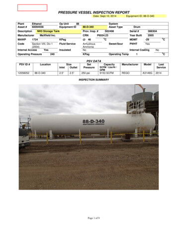
Transcription
Transactions on Modelling and Simulation vol 27, 2001 WIT Press, www.witpress.com, ISSN 1743-355XPressure vessel design using boundary elementmethod with optimizationR.E. Dippery, Jr. & D. SrivastavaKettering University, Michigan, USAAbstractDesign of pressure vessels is covered by references such as the ASME PressureVessel Code and textbooks devoted to pressure vessel design. Detailed stressanalysis, particularly in the area of discontinuities, is generally left to the designengineer. The type discontinuity addressed in this paper is the design of boltedflanges for a pressure vessel. Work for this project involves optimization of the hubcontour using the ASME Pressure Vessel Code requirements as constraints. Thispaper summarizesthe initial work, development of the BEM (BEASY) models andverification of the model to classical techniques such as a "Roark." [12]. This twodimensional model will later be expanded to a full, threedimension model; an4will also provide data for establishing allowable defect sizes, based upon inspectiontechniques and design life.Pressure vessel designDesign of pressure vessels is governed by the ASME pressure vessel code [l].Other textbooks such as Farr [2], Moss [3], Chuse [4], Harvey [5], B&[6], andGill [7], provide valuable insight and guidelines to pressure vessel design. Boltedflange analysis is discussed in machine design textbooks such as Norton [8] orspeciality books such as Bickford or Blake [9, 101 or company design practices orcriteria. Detailed stress analysis, particularly in the area of discontinuities, isgenerally left to the design engineer. Different type stresses are defined byappend 4 of the ASME code [l]. Stress limits,(allowable stress magnitudes),based upon the type stress, are addressed by Appendix 4 (Mandatoly Design Basedon Stress Analysir) of the ASME code [l]. These are discussed later in this paper.
Transactions on Modelling and Simulation vol 27, 2001 WIT Press, www.witpress.com, ISSN 1743-355XThe type discontinuity addressed in this paper is one associated withdesign of bolted flanges for a pressure vessel. Figure l a illustrates one type designwhich consists of the shell welded to the flange. Figure l b illusmm another typedesign, a hubbed flange, with the weld located away from the shewflangediscontinuity. This is done to locate the weld in an area of lower bending stress,improving the strength of the joint; an4 also to locate it in an area where it mayrequire less weld material (cost) and can be more easily inspectedFigure l a - Basic ConfigurationFigure l b - Hubbed Configurationr r,,rt or hHXFlange Outer WusBolt Circle RadiusShell (Vessel) Inner RadiusShell (Wall) ThicknessFlange ThicknessDistance From Joint (Discontinuity) to WeldBending moments at a discontinuity, such as a flange, will generally belocal and diminish in magnitude as the distance fiom the dscontinuity is increased.Refemng toTirnoshenko[l l], when the term X 3.0, the moment effect is almostzero.
Transactions on Modelling and Simulation vol 27, 2001 WIT Press, www.witpress.com, ISSN 1743-355XvahXPoisson's RatioShell RaQusVessel (Shell) ThicknessAxial Distance from DiscontinuityUsing the ASME Code, previously mentioned references, and handbookssuch asRoark[l2]pressure vessel design could be a very complex task. With theadvent of the computer age, techmques such as the finite element method (FEM)and boundary element method (BEM) became very valuable design and analysisaids.Section VIII, Division 2 of the ASME Code defines several category ofstresses: Primary, Secondary, and Peak. A primary stress is a normal or shearstress developed by the imposed loading and necessary to satisfy the laws ofequilibrium, such as the hoop (primary membrane) stress resulting from internalpressure in a shell. Secondary stresses are normal or shear stress developed by theconstraint of adjacent parts or the self-constrain of a structure, a bendng stress ata gross structural discontinuity. The basic characteristic of a secondary stress is itis self-limiting, local yielding and minor distortions can satisfy the conditionswhch cause to stress to occur. Apeak stress is a stress which does not cause anynoticeable Qstortion and is undesirable because it may be a possible source of afatigue crack or brittle fracture, for example, the stress at a local structuraldiscontinuity. Definitions of all terms and tables of combinations and allowablestresses are provided in Appen&x 4 of Section VIII, Division 2. hovisions forplastic, limit, experimental, shakedown, and fatigue analysis are also available inthls same section of the Code.Coupled with the stress analysis are design considerations for failureanalysis. Allowable defect limits must be determined by the designer, even withthe Code allowable limits. "Leak before failure", design life, damage tolerance areall factors which must be considered in the design process. Once again textbooksand handbooks, such as Collins [13], Dowling [14], Tada and Paris [IS], Maddox[16], Brooks and Choudhury [17], and Barson and Rolfe [l81 are available fordesign reference.Boundary element analysis with optimizationThe use of BEM is not new to pressure vessel analysis as evidenced by
Transactions on Modelling and Simulation vol 27, 2001 WIT Press, www.witpress.com, ISSN 1743-355X270Bortrzdar; Elen e,trTechnology XlVTrevetyan [l91 and Floyd [20]. Fracture and crack growth using BEM is alsoevidenced by textbooks such as Prasad [2 l], Aliabadi [22][23], Monahan [24], andLeitao [25]. A test model, as shown by Figure 2, has been run to venfy BEMresults. 'Ile model was based upon a flanged and bolted pipe. The model wasverified using equations fiom Table XIII, case 32 of Roark [12]. Results of thismodel were comparable to the "hand calculations" of Roark.Like the boundary element method, optimization techniques have beenenhanced by the continued growth of computers. Vanderplaats [26] is one of thosewho has been part of this growth as well as others suchas Chanrupatala and Belegundu [27. The work beingperformed in conjunction with this paper is based upondesign of a hubbed flange, subject to the requirementsof the ASME Code, using the boundary elementmethod. BEASP [28] and VisualMX1" [29] are thesoftware codes selected for this work In other words,what is being accomplished is to optimize a designbased upon BEM analysis with constraints imposed bycodes such as the ASME Pressure Vessel Code.A criterion or objective "function" must bedeterminedwhich will satisfy inequality; and, possibly,equality constraints. In turn, the objective must beminimized (or maximized, depending upon theproblem.) For a simple function, this meansdetermining where the first derivative is zero, and ifFigure 2 thesecond derivative is positive or negative at thoseBEASY Modelpoints. Furthermor;, at those points, the design orobjective must satisfy all &nstraints. That is, the solution must befeasible.The actual problem is somewhat more complex. The first questionbecomes what is to be minimized? In this case, it will be weight. Although, withsuflicient time and thought, this can be translated into cost, considering fabricationcosts, inspection costs, and material costs. Weight should provide a good workingmodel. Constraints will be to satisfy the stress limits of the ASME Code and theweld to be in a low bending stress area ( X r 3.0). As the work progresses, costand multi-objective function problems will be developed. The final step will be tointroduce crack propagation constraints into the models.ConclusionsInitial results show the boundary element method will provide accurate predictionsof the stresses in a pressure vessel flange. With further development, an optimumhub contour and weld location, subject to pressure vessel code and other
Transactions on Modelling and Simulation vol 27, 2001 WIT Press, www.witpress.com, ISSN 1743-355Xconstraints will be obtained. Once this methodology has been established, thework will be expanded to three-dimensional models. Flange-opening under loadscan then be considered, with local stiffening, as a function of angular location, aconsideration in the methodology to be developedReferencesThe American Society of Mechanical Engineers, 1998ASME Boiler andPressure Vessel Code, Division 2 -Alternative Rules, ASME, 1998.JR F a n and MH Jawad, Guidebookfor the Design ofASME Section YlllPressure Vessels, ASME Press, 1998DR Moss, Pressure Vessel Design Manual, Gulf Publishing Company,1987R Chuse and BE Carson, Sr., The ASME Code SimplijiedPressureVessels,7th Edition, McGraw-Hill, 1993JF Harvey, Theory and Design of Pressure Vessels, 2" Edition, VanNostrand Reinhold, 1991HH Bednar, Pressure Vessel Design Handbook, 2"" Edition, VanNostrand Reinhold, 1986SS Gill, The Stress Analysis of Pressure Vessels & Pressure VesselComponents, Pergamon, 1970RL Norton, Machine Design - An Integrated Approach. 2ne Edition,Prentice-Hall, 2000.JH Bickford, An Introduction to the Design and Behavior ofBoltedJoints, 3* Edition, Dekker, 1995A Blake, Design of Mechanical Joints, Dekker, 1985S Timoshenko and S WoinowslyKreiger, Theory of Plates and Shells,2ndEdition, McGraw-Hill, 1968RJ Roark, Fomulasfir Stress andStrain, 4thEdition,McGraw-Hill, 1965JA Collins, Failure of Materials in Mechanical Design, 2"' Edition,Wiley, 1993.NE Dowling, Mechanical Behavior ofMaterials, 2ndEdition, PrenticeHall, 1999H Tada, PC Paris, GR Irwin, The Stress Analysis of Cracks Handbook,3* Edition, ASME Press, 2000.SJ Maddox, Fatigue Strength of Welded Structures, 2"" mtion,Abington, 1998.CR Brooks and A Choudhury, Metallurgical Failure Analysis, 2ndEdition, McGraw-Hill, 1993.JM Barson and ST Rolfe, Fracture & Fatigue Control in Structures Applications of Fracture Mechanics, 2"dEdition, Prentice-Hall, 1987.
Transactions on Modelling and Simulation vol 27, 2001 WIT Press, www.witpress.com, ISSN 1743-355XJ Trevelyan, Boundary Elements for Engineers - Theory andApplications, Computational Mechanics Publications, 1994.CG Floyd, The Determination of Stresses Using a Combined Theoreticaland Experimental Analysis Approach Computational Methods andExperimental Methods, Proc., 2"* International Conference, CMP, 1984NNV Prasa4 Thermomechanical Crack Growth using BoundaryElements, WIT Press, 1998.MH Aliabadi, Dynamic Fracture Mechanics, Computational MechanicsPublications, 1995.MH Aliabadi, CA Brebbia, and VA Parton, Static and Dynamic FractureMechanics, Computational Mechanics Publications, 1994.CC Monahan, Early Fatigue Crack Growth at Welds, ComputationalMechanics Publications, 1995.VMA Leitao, Boundary Elements in Nonlinear Fracture Mechanics,Computational Mechanics Publications, 1994.GN Vanderplaats, Numerical Optimization Techniquesfor EngineeringDesign, 3"' Edition, VR&D, 1999AD Beiegundu & TR Chandrupatla, Optimization Concepts andApplications in Engineering, Prentice Hall,1999-, BEASY User Guide, Volumes 1 & 2, Computational MechanicsBEASY Ltd, 1998.MsualDOC, Vanderplaats Research and Development, 1999.
HH Bednar, Pressure Vessel Design Handbook, 2"" Edition, Van Nostrand Reinhold, 1986 SS Gill, The Stress Analysis of Pressure Vessels & Pressure Vessel Components, Pergamon, 1970 RL Norton, Machine Design - An Integrated Approach. 2ne Edition, Prentice-Hall, 2000. JH Bickford, An Introduction to the Design and Behavior ofBolted Joints, 3* Edition, Dekker, 1995 A Blake, Design of Mechanical .