Transcription
RCU (Remote Control Utility)PC-RMS User ManualVersion 1.002/2017
CopyrightSmartHarvest by OutBack Power represents a line of renewable energy electronics aimed atmeeting the growing global demand for value-oriented, low power-range renewable energysystem components.North AmericaLatin AmericaEuropeAsiaTel: 1 360.435.6030Fax: 1 360.435.6019Tel: 55 11.24760150Tel: 49 9122.79889.0Tel: 852 2736.8663Cell: 55 11.988.458688 Fax: 49 9122.79889.21 Fax: 852 2199.7988Pacific AustraliaTel: 61 (2) 8003.3760Cell: 61 466.986.155Website: www.smartharvestbyoutback.comSMARTHARVEST BY OUTBACK POWER:(a) MAKES NO WARRANTY AS TO THE ACCURACY, SUFFICIENCY OR SUITABILITY OFANY TECHNICAL OR OTHER INFORMATION PROVIDED IN ITS MANUALS OR OTHERDOCUMENTATION. (b) ASSUMES NO RESPONSIBILITY OR LIABILITY FOR LOSS ORDAMAGE, WHETHER DIRECT, INDIRECT, CONSEQUENTIAL OR INCIDENTAL, WHICHMIGHT ARISE OUT OF THE USE OF SUCH INFORMATION. THE USE OF ANY SUCHINFORMATION WILL BE ENTIRELY AT THE USER’S RISK. (c) RESERVES THE RIGHT TOMAKE CHANGES TO THE PRODUCTS AND INFORMATION CONTAINED IN THISDOCUMENT WITHOUT NOTICE.Revision A, Dec 2016 2016 OutBack Power Technologies. All Rights Reserved.2
Table of ContentsContents1. Abbreviations . 82. Introduction . 92.1 Overview . 92.2 Key Features . 93. PC-RMS Download and Installation . 103.1 Installation Procedure . 103.2 Running PC-RMS for the first time . 124. Remote Monitoring System Window . 164.1 Status Panel. 164.1.1 Live Readings . 164.2 Graphs . 174.3 Data Table . 184.4 Menu Bar . 194.4.1 File . 194.4.2 View. 204.4.3 Options . 204.4.4 Product . 214.4.5 Mode . 224.4.6 Configure . 224.4.7 Help Menu . 255. Product Specific Screens . 275.1 SmartHarvest SCCM 20/10 . 275.2 SmartHarvest SCCP 5/10 . 295.2.1 Status Panel . 296. Setting up SCOM-USB Module . 316.1 Hardware installation . 316.2 Driver Installation . 323
Table of FiguresFiguresFigure 1: PC-RMS download link. 10Figure 2: RMS Zip file . 10Figure 3: RMS set up license . 11Figure 4: RMS Set Up . 11Figure 5: Application Install – Security Warning . 11Figure 6: Product Category . 12Figure 7: SmartHarvest Products . 12Figure 8: Select Communication . 13Figure 9: Gateway Conn . 13Figure 10: Device Manager . 13Figure 11: Scan for Devices . 14Figure 12: Search Device ID option . 14Figure 13: Search Device ID option 2 . 15Figure 14: Data Polling Option . 15Figure 15: Remote Monitoring System Main Window . 16Figure 16: Live Readings . 16Figure 17: Alerts . 17Figure 18: Graphs . 17Figure 19: Zoom All Function . 18Figure 20: Data Table . 18Figure 21: File Menu . 19Figure 22: Export Data . 19Figure 23: Open Data Directory . 19Figure 24: View menu . 20Figure 25: Options Menu . 20Figure 26: Change Polling Time . 21Figure 27: Settings . 21Figure 28: Product Wizard . 21Figure 29: Mode . 22Figure 30: Configure . 22Figure 31: Battery Settings . 22Figure 32: Enable Change in Battery Settings . 23Figure 33: Night Light Settings . 24Figure 34: Identity Settings . 25Figure 35: Help Menu . 25Figure 36: Shortcuts . 26Figure 37: SCCM 20/10 . 27Figure 38: SCCM 20/10 Status Panel . 27Figure 39: SCCM 20/10 Data Table . 28Figure 40: SCCM 20/10 Export Data . 28Figure 41: SCCP 5/10 . 29Figure 42: SCCP 5/10 Status Panel . 29Figure 43: SCCP 5/10 Data Table. 30Figure 44: SCCP 5/10 Export Data . 30Figure 45: Connection with SCCM 20/10 . 31Figure 46: Connection with SCCP 5/10 . 31Figure 47: File Location . 32Figure 48: Setup File . 324
Figure 49: Installation Wizard . 33Figure 50: License Agreement . 33Figure 51: Device Driver Installation wizard . 34Figure 52: Installation complete wizard . 34Figure 53: COM port number popup . 345
Safety InformationSave these InstructionsThis manual contains important safety, installation and operating instructions.The following symbol is used throughout this manual to indicate important safety instructions.Please take care when meeting these symbols.NOTE: Indicates a procedure or function that is important for the safe and proper operation of PCRMS.6
About the BookAt a GlanceDocument ScopeThis manual is designed for the PC-Remote Monitoring System (PC-RMS) software users. It provides anoverview of the capabilities of the PC-RMS in solar energy harvest monitoring. However, it is not intendedto be an exhaustive reference manual for PC-RMS. Instead, it is a guide that explains the features of thesoftware, specifications, download, and installation procedure to the user.Related Documents User Manual of SCCP User Manual of SCCM User Manual of SCOM-USBTechnical publication and other technical information can be downloaded fromwww.smartharvestbyoutback.com.7
AbbreviationsChapter 1: Abbreviations1. CCPCommunicationPhotovoltaicRemote Monitoring SystemSmartHarvest Charge Controller MPPT series productSmartHarvest Charge Controller PWM series productSCOMUSBVRLACCUSmartHarvest Communication Module series productUniversal Serial BusValve-Regulated Lead-AcidCharge Controller Unit8
IntroductionChapter 2: Introduction2. Introduction2.1 OverviewThe PC-Remote Monitoring System (PC-RMS) is used to display, monitor, and configure the workingparameters of SmartHarvest products. It is used to monitor connected devices to RS-485 bus. For SCCMseries of products, PC-RMS enables the users to customize and configure a wide range of parameters.User can run this software in Microsoft Windows , workstation or notebook. It is supported by customcommunication hardware (SCOM-USB) to interface with the device to be monitored.2.2 Key FeaturesThe key features of PC-RMS are: Enables live data monitoring with a real time clock. Provides charge controller parameters in graphs and tables. Provides alert and indication for panel voltage, battery voltage, unit temperature, etc. Provides data table to view the parameters of charge controllers after every poll. Enables customization of the polling interval time from seconds to 1 hour. Enables configuration of battery settings, night light settings, identity settings, charging current forbattery, and battery equalization charge for SCCM charge controllers. Enables to view the Exports logged data (.csv) in Microsoft Excel or equivalent spread sheetapplication. Provides long term storage without memory limitation.9
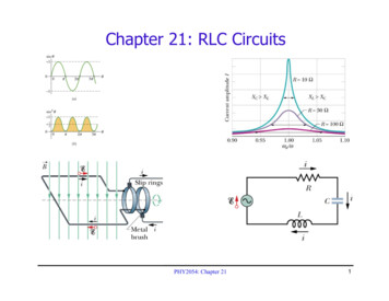
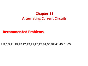
PC-RMS Download and InstallationChapter 3: PC-RMS Download and Installation3. PC-RMS Download and Installation3.1 Installation ProcedureFollow the steps to download and install the PC-RMS:1. Click the following link to download the PC-RMS.www.smartharvestbyoutback.com.Figure 1: PC-RMS download link2. After download is complete, click Open.3. Unzip and extract the required files.4. Click setup.exe to install.Figure 2: RMS Zip file10
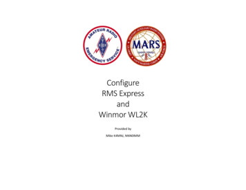
PC-RMS Download and Installation5. Accept the terms and conditions of license agreement.Figure 3: RMS set up license6. After clicking Accept, the system will automatically start downloading.Figure 4: RMS Set Up7. Click Install to start PC-RMS installation.Figure 5: Application Install – Security WarningNOTE: PC-RMS downloads about 80 MB of supporting files for its very first installation.Internet connection is required.11
PC-RMS Download and Installation3.2 Running PC-RMS for the first timeNOTE: Refer section 6. Setting up SCOM-USB Module. page no. 31 to set up the chargecontroller with SCOM-USB.After the installation is complete, follow the instructions to run the software for the first time.1. Click and open PC-RMS from the Start menu.2. Select SmartHarvest Products and click Next as shown in the following figure.Figure 6: Product Category3. Select the product from the drop-down list and click Next.Figure 7: SmartHarvest Products4. Select USB from the Select Communication options as shown in the following figure.12
PC-RMS Download and InstallationFigure 8: Select Communication5. Select the COM port number from the Gateway Port drop-down list (Refer 6.2 Driver Installation pageno. 32) and click Next.Figure 9: Gateway ConnNOTE: To check the COM port number, click Run from the start menu and enterdevmgmt.msc. System opens the Device Manager. Open Ports (COM & LPT) to find thevirtual port number. If multiple ports are available, disconnect and connect the USB cable toidentify the correct virtual port.Figure 10: Device Manager13
PC-RMS Download and Installation6. Enter the device ID and click Next.Figure 11: Scan for DevicesNOTE: If the ID of the charge controller is unknown, use either of the following option: Select Search and enter the range (defined: 1 to 10). Range is charge controllers’ device ids. ClickScan. PC-RMS scans and displays the devices which are connected and communicating under thatrange in the network. Select the device and click Start.Figure 12: Search Device ID optionNOTE: “Listen Mode” tab and settings are not applicable to charge controllers.14
PC-RMS Download and InstallationClick Range tab and enter the range. PC-RMS displays the devices connected (communicating or notcommunicating) under that range in the network. Select the device and click Next.Figure 13: Search Device ID option 27. Select the target unit by selecting the checkbox under Poll. Select time and unit of time from thePolling Interval drop-down list. Click Start button to initiate data polling.Figure 14: Data Polling Option8. PC-RMS monitoring page pops up and displays the charge controller data.15
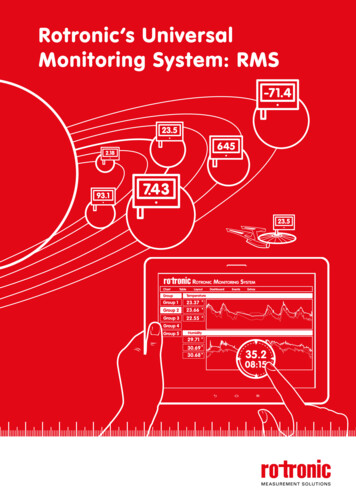
Remote Monitoring System WindowChapter 4: Remote Monitoring System Window4. Remote Monitoring System WindowThe main window of Remote Monitoring System is shown in the following figure.Figure 15: Remote Monitoring System Main Window4.1 Status Panel4.1.1 Live ReadingsThe live readings panel shows the snapshot of overall operating parameters of the device.ReadingsPV kWhDescriptionDisplays the total energyharvested by the CCU.Solar PanelDisplays the present panelvoltage and panel current.BatteryDisplays the battery voltage,battery current, battery chargingmode, and battery temperature.LoadShows the load current and theload On/Off status.Figure 16: Live Readings16
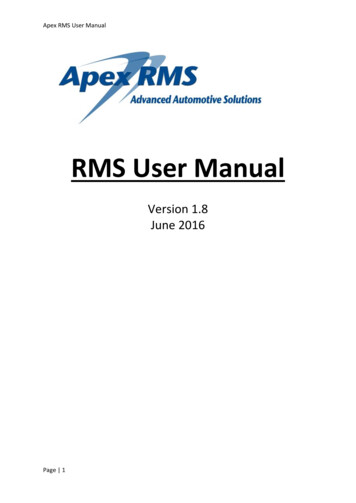
Remote Monitoring System Window4.1.2 AlertsThe Alerts panel provides indication to notify the parameters operating ranges.Green indication shows the operating parameters are within the band and red indications shows the parametersare out of band.Below screen shot shows the panel voltage, battery voltage and temperature parameters with green indicationswhich means these are within the safe operating band.Figure 17: Alerts4.2 GraphsFigure 18: GraphsPC-RMS shows the graph to view the voltage, current, unit temperature, and kWh readings. The Y-axisindicates a selectable parameter (voltage, current, etc.) and the X-axis indicates the date/time as shown in thefollowing figure.17
Remote Monitoring System WindowBelow is an explanation of the graph callouts:1. The identification of the device. If multiple devices have been selected for polling, this drop downwill allow you to view the data of the selected device, so you will be able to selectively view thepolled devices data based on this selection.2. Select a date range from the drop-down and click Show to change the graph displayed.3. To view the parameters of the current date, click Today’s Data button.4. Select the parameters of the graphs from the drop-down list.5. Displays the values of selected graph parameters.6. Indication of graph colors according to selected graph parameters key.7. The voltage graph.8. Click the Zoom All button to see the data since the beginning in graph. To zoom in, click at anypoint on the graph and drag it to the point required to zoom in. PC-RMS shows the zoomed graphas shown in the following figure.Figure 19: Zoom All Function9. The current graph.10. X-axis represents the date/time.11. Y-axis represents the values of selected graph parameters.4.3 Data TablePC-RMS updates the data in the Data Table after every poll. A moving blue cursor indicates the new dataadded to the table in the top row. Each line of data has columns for date and time. The parameters shown onthe data table are same as that on the live readings, but the variation in parameter readings can also beobserved by scrolling down. PC-RMS erases the data table after a restart. However, previously logged data canbe downloaded and viewed as described in the section 4.4.1 File page no. 19.Newly addeddataFigure 20: Data Table18
Remote Monitoring System Window4.4 Menu Bar4.4.1 FileExport DataFigure 21: File MenuFollow the steps to export the data from PC-RMS.1. Click Export Data on the File menu. It opens Export Data window as shown in the following figure.Figure 22: Export Data2. Click Browse button and select the location to export the file.3. Select the From and To dates from the drop-down calendar.4. Click Export To Excel.PC-RMS provides data in .CSV file which is suitable for viewing in Microsoft Excel or any standard spreadsheet application.Open Data DirectoryFigure 23: Open Data Directory19
Remote Monitoring System Window1.2.3.4.Click Open Data Directory to view the exported .CSV file.Clear DatabaseClick Clear Database to delete all logged data from the internal database.ExitClick Exit to close the PC-RMS window.4.4.2 ViewData TableFigure 24: View menuClick Data Table on the View menu and select the checkbox. It displays the data in a table form after every poll(Refer 4.3 Data Table page no. 18).4.4.3 OptionsFigure 25: Options Menu1. ConnectThe Connect option provides a reconnection to a previously established connection.2. DisconnectIf the PC-RMS is already connected, this option enables to disconnect the PC-RMS.3. Change Poll TimeClick Change Poll Time on the Options menu and set the polling interval between two sessions asshown in the following figure. Minimum polling interval is 3 seconds.20
Remote Monitoring System WindowFigure 26: Change Polling Time4. SettingsClick Settings on the Options menu to change the unit of temperature readings to Fahrenheit or Celsius.Figure 27: Settings5. Get F/W VersionClick Get F/W Version the Options menu to view the firmware version of charge controller connected. Asshown in Figure 25: Options Menu page no. 20.6. Restart CCUTo restart the charge controller, click Restart CCU in the Options menu. As shown in Figure 25: OptionsMenu page no. 20.7. Reset PV kWhTo reset the solar panel data, click Reset PV kWh on the Options menu. As shown in Figure 25: OptionsMenu page no. 20.4.4.4 ProductProduct WizardFigure 28: Product WizardClick Product Wizard on the Product menu and follow the steps mentioned under 3.2 Running PC-RMS forthe first time page no. 12.21
Remote Monitoring System Window4.4.5ModeFigure 29: ModeCommandThis is the default operating mode where PC-RMS acts as a bus-master. It sends commands to targetdevices, receives data, displays data, and saves it into the database.4.4.6ConfigureFigure 30: ConfigureTo configure various parameter settings of the charge controller, click Change Controller Settings onConfigure menu. The application opens a new window to configure various settings.NOTE: The Configure feature is applicable only for the SCCM charge controllers. Data loggingdoes not happen if the Change Controller Settings window is open.Battery SettingsFigure 31: Battery Settings22
Remote Monitoring System WindowBelow is an explanation of the graph callouts:1. Nominal voltage – specifies the nominal battery voltage of the controller.2. Type–specifies the battery type which is dependent on the jumper settings of the charge controllerhardware.NOTE: Refer user manual of SCCM charge controller for more details regarding battery type.3.Modify threshold values- The battery charging thresholds can optionally be changed by the user.NOTE: The default battery threshold preset on the charge controller shall work fine for most ofthe installations. Only a qualified battery specialist must attempt to change the default settings.Following are the parameters that can be modified by using this optiona. Battery charging levels-Bulk, Absorption and Floatb. Exit Currentc.Battery low load disconnectd. Load Reconnecte. TimeCheck the Modify threshold values (callout 3) checkbox to set parameter thresholds. After clicking thecheckbox, enter the password and click OK. Password: “smart123”.Figure 32: Enable Change in Battery Settings4. Charge Level – Indicates the approximate battery state of charge.5. Initiate - Click Initiate to start the equalization charging mode.23
Remote Monitoring System WindowNOTE: The charge controller will automatically initiate equalization charge at regular intervals6. Charging Current- Shows the default charging current of the battery bank. It can be set less than orequal to the maximum capacity of the charge controller.NOTE: The default battery threshold preset on the charge controller is sufficient for most of theinstallations. Only a qualified battery specialist must attempt to change the default settings.7. Capacity- The capacity of the battery connected to the system has to be set by the user duringinstallation. This is mandatory for accurate indication of the state-of-charge of the battery.After changing settings in all tabs, click Save to make the new settings saved to the charge controller.Click Abort to revert to the previous settings.Click Close to revert to the PC-RMS data window.Night Light SettingsPC-RMS keeps the sleep mode on by default. Certain charge controllers support night-light control feature. Inthis case, the controller can be configured to turn on a load in a preset sequence between dusk and dawn.The Enable Night Light checkbox must be selected to activate this mode. Upon selection of Enable NightLight, Enable Sleep mode checkbox gets deselected. The steps to configure night-light are explained in theexample below.Sleep mode: The charge controller will be in sleep mode when neither an active solar panel nor load isconnected to the unit. There will be no communication with the unit in this mode.The unit shall recover from sleep mode upon connecting an active solar panel or connecting DC load. Thesleep mode will be inactive when nightlight function is enabled or load timer function is programmed by theuser.Figure 33: Night Light Settings24
Remote Monitoring System WindowOn sensing Dusk – Block 1 timeBlock 2 timeTurns ON Load for 5 hoursTurn OFF Load for 5 hoursBlock 3 - Before sensing DawnRemaining time –Turn ON Load for 2 hoursIn the example, the initial turn on time is specified as 5 hours; on detecting dusk, the charge controller will turnon load for this block of time.The subsequent turn off time is specified as 5 hours; after the elapse of first 5 hours after dusk, the load will beturned off for 5 hours.The balance time is the residual time before dawn (which depends on the geographic location and local time),during which the load will be turned on again.After changing settings in all tabs, click Save to make the new settings saved to the charge controller.Click Abort to revert to the previous settings.Click Close to revert to the PC-RMS data window.Identity SettingsDevice ID is a unique numeric value assigned to the charge controller on a RS-485 bus. When multiple devicesare connected to the same bus, the user has to ensure that each device has a unique ID.Also, the ID shou
PC-RMS Download and Installation 10 Chapter 3: PC-RMS Download and Installation 3. PC-RMS Download and Installation 3.1 Installation Procedure Follow the steps to download and install the PC-RMS: 1. Click the following link to download the PC-RMS. www.smartharvestbyoutback.com. Figure 1: PC-RMS download link 2. After download is complete, click .