Transcription
Chapter 11Alternating Current CircuitsRecommended 41,43,61,65.
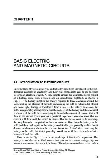
Alternating Current SourcesGenerator or dynamo isa device that operateaccordingtotheelectromagnetic inductionand Faraday's law.It is a device thatproduces a current byconvertingthemechanical energy intoelectrical energy.Figure 33.1 Schematic diagram of a generator.It consists of a loop of wire that can rotate, by an external means,in a magnetic field. The ends of the loop are connected to sliprings that rotate with the loop. The slip rings are connected to theexternal circuit by two fixed brushes.
As the loop rotate, the magnetic flux through it changes with timeinducing an emf and so a current in the external circuit.Suppose that the loop, with area A, rotates with constant angularspeed , and suppose that is the angle between the magneticfield and the area of the loop. The magnetic flux through the loopat any time is then m BA cos BA cos t Therefore, the induced emf in the loop is given byd m AB sin t max sin t dtThis means that the emf varies sinusoidally withtime forming a sinusoidal wave, as shown in thefigure. Because of that a source of AC isrepresented in the circuits by the symbol
Thefrequencyofcommercialgenerators in our country and most ofthe world is 50 Hz, while it is 60 Hz insome other countries like the USA andCanada. Note that the frequency f isrelated to the angular speed throughthe relation . 2 fOhm’s law is still hold for AC circuits,i.e., maxt- maxIIo maxI sin t RRI I m sin t t-IoIThe voltage across an element in anAC circuit is given byV Vm sin t t(a)
Im and Vm are called the peak current and the peak voltage,respectively.As it is clear from Figure 14.7(b), the average value of an AC iszero. This doesn't mean, however, that no power is needed or thatno heat is produced in a resistor. Electrons for AC move forth andback and so produce heat.It is known that the power dissipated in a resistor is given byP I 2 R I m2 R sin 2 t Since the current is now squared, the power is always positive.12It is easy to show that the average value of sin t 222I is 12 I mAnd so the average value ofthe average power dissipated in a resistor in AC circuits is then2VP 12 I m2 R 12 mR
That is, what is important for calculating the average power is themean value of the square of the current or voltage. The squareroot of each of these values is known as the rms (root-meansquare) and is given byVmImVrms I rms 22The rms values of V and I are sometimes known as the effectivevalues. They are useful because they can be substituted directlyinto the famous power formula to get the average power, that is,2V2P I rms Vrms I rmsR rmsRIt is the rms values that are specified or measured. Therefore,ammeters and voltmeters are designed to read the correspondingrms values. When we say that the standard voltage in our countryis 220 V, we mean that the rms value of V is 220V.The peak value of such a voltage isVm 2 Vrms 311V
Phasor: It is a counterclockwise-rotating vector representing anAC quantity such that its length represents the maximum value ofthe quantity and its projection onto the vertical axis represents theinstantaneous value of the quantity.I vs t tIt is clear that the instantaneous value is changing with time as thephasor rotates while the maximum value is constant.
Test Your Understanding (1)vvvv(a)(b)(c)(d)Consider the voltage phasor shown. Choose the figure at whichthe instantaneous value of the voltage has the largest magnitude.(a)(b)(c)(d)Choose the figure at which the instantaneous value of the voltagehas the smallest magnitude.(a)(b)(c)(d)
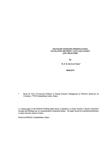
Example 33.1A 900.-W microwave oven is designed tooperate at 220. V. Calculate its resistance and the peak currentwhen it is operating.22Vrms 220Solution: To find the resistance we have R 53.8 P900And for the current we haveP 900I rms 4.09 A Vrms 220I m 2 I rms 5.78 ARResistors in AC CircuitsConsider the circuit that consists of aresistor and connected in series with anAC source.v Vm sin tLet vR, be the voltage at some instant across the resistor. Thisvoltage must equal to the voltage of the AC source, that isvR Vm sin t
The current passing through the resistor isvR Vm sin ti I m sin tRRAs it is clear from the last two equations thatThe current i and voltage vR across a resistor in a pure resistiveAC circuits are in phase.iR, vRImiR, vRiRVmtvR t
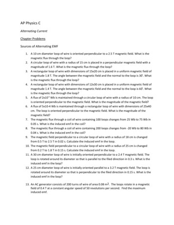
Inductors in AC CircuitsLConsider the circuit that consists of aninductor and connected in series withan AC source.Let vL, be the voltage at some instantacross the inductor. Again this voltagemust equal to the voltage of the ACsource, that isv Vm sin tvL Vm sin tTo find the current passing through the inductor we havedivL L dtVmVm1i vL dt sin( t ) dt cos( t ) LL L
Using the identitysin t 2 cos( t ) Vmi sin t 2 I m sin t 2 Lwith I m and X L LVmXLIs called the inductive reactance.The current i lags behind the voltage vL across an inductor in apure inductive AC circuits by 90o .
iR, vRiR, vRImvRVmVm ttImiR
Test Your Understanding (2)Consider the AC circuit shown. Thefrequency of the AC source is adjustedwhile its voltage amplitude is heldconstant. The lightbulb will glow thebrightest ata) high frequenciesb) low frequenciesc) all frequencies.d) It will not glow at all
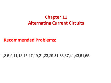
Capacittors in AC CircuitsConsider the circuit that consists of acapacitor connected in series with anAC source.Let vC, be the voltage at some instantacross the i capacitor. Again thisvoltage must equal to the voltage ofthe AC source, that isCv Vm sin tvC Vm sin tTo find the current passing through the capacitor we haveq CvC i dvdq C C CVm cos( t )dtdt
Using the identitysin t 2 cos( t ) i C Vm sin t 2 I m sin t 2 with I m 1and X C CVmXCIs called the capacitive reactance.The current i leads the voltage vC across a capacitor in a purecapacitive AC circuits by 90o .
iR, vRiR, vRiRImImVmvRtVm t
Test Your Understanding (3)Consider the AC circuit shown. Thefrequency of the AC source is adjustedwhile its voltage amplitude is heldconstant. The lightbulb will glow thebrightest ata) high frequenciesb) low frequenciesc) all frequencies.d) It will not glow at all
Test Your Understanding (4)Consider the AC circuit shown. Thefrequency of the AC source is adjustedwhile its voltage amplitude is heldconstant. The lightbulb will glow thebrightest ata) high frequenciesb) low frequenciesc) all frequencies.d) It will not glow at all
SERIRS RLC AC CIRCUITSConsider the circuit which consists of aresistor, an inductor, and a capacitor,connected in series with an AC source. LetvR, vL, and vC be the voltage at some instantacross each element, respectively.RLCv Vm sin tSince they are connected in series, the voltage across thecombination isv vR vL vCThis voltage must equal to the voltage of the AC source, that isVm sin t vR vL vCNote that a voltmeter, when connected across the combination,does not read (VR)rms (VL)rms (VC)rms . What will read then? Letus see.To solve this equation we use the phase diagram by letting thephasor representing I to be along the horizontal axis
Supposing the current passing through each element (which is thesame due their series connection) to be given asI I m sin t where the constant is called the phaseangle between the current and theapplied voltage. Now we havevR IR I m R sin t vL I m X L sin t 2 vC I m X C sin t 2 The phase diagram is nowVLVm VCImVRVmVL-VC VR
From the diagram we conclude that2VL VCtan VRVR I m RVL I m X LVm VR2 VL VC Using the relationsVC I m X C Vm I m R 2 X L X C 2 I m ZZ R 2 X L X C 2With Z is called the impedance of the circuit with its unit is . Thephase angle is now given asX L XCtan RFrom the last two equations we conclude that
if the circuit consists only of a resistor with the source, (XL XC 0), we have Z R, and the phase angle is zero, that is I and V arein phase. if the circuit consists only of an inductor with the source, (R XC 0), we have Z XL, and the phase angle is 90o, that is I lagsbehind V by 90o . if the circuit consists only of a capacitor with the source, (R XL 0), we have Z XC, and the phase angle is -90o, that is I leads Vby 90o . In general if XL XC the phase angle is ve, and I lags behindV by . In the other hand if XL XC the phase angle is -ve, and IleadsV by When XL XC then phase angle 0. In this case, theimpedance equals the resistance and the current has its peakvalue given byVm R
The frequency o at which this occurs is called the resonancefrequency of the circuit. Using the condition XL XC we get1 o L o C o 1LC
Test Your Understanding (6)Indicate each part of the figure shown whetherXL XC , XL XC , XL XC .a) XL XCc) XL XCb) XL XC
Example 33.4In a series RLC circuit we have Vm 120 V,R 200 , C 4.0 F and f 60 Hz. Find L such that the voltageacross the capacitor lags the applied voltage by 30o.SolutionSince the angle is between theapplied voltage and the voltageacross R, and since the anglebetween VR and VC is 90o VLVC 30 90 60oNow X C oo11 663 6 C 2 (60)(4 10 )X L XCX L 663tan 1.73 R200317 317X L 317 L L 0.83 H2 f 120 ImVR30oVm
Example 33.4In a series RLC circuit we have Vm 150 V,R 425 , C 3.5 F, L 1.25 H, and 377 s-1 .a) Determine Z.b) Find the maximum current in the circuit.c) Find the phase angle.d) Find the maximum voltage across each element.SolutionLet us first find the reactancesX L L 377 1.25 471 a) The impedance is thenz R 2 X L X C 2 X C 1 C 1 377 3.5 10 6 758 425 2 471 758 2 513 b) The maximum current is given byVm 150Im 0.292AZ 513
c) The phase angle is given byX L X C 417 758tan 34oR425.Note that since the circuit is more capacitive (XL XC ), thecurrent leads the applied voltage by the angle 34od) For the maximum voltage across each element we haveVR I m R 124 VVL I m X L 138 VVR I m X C 221V
Power in AC CircuitsThe instantaneous power delivered by Ac source isP iV I max sin( t )Vmax sin( t )using sin t sin t cos cos( t ) sin P I maxVmax sin 2 ( t ) cos I maxVmax sin( t ) cos( t ) sin Pavr I maxVmax sin 2 ( t ) avr cos sin( t ) cos( t ) avr sin Knowing that Pavr sin 2 ( t ) avr 121 I maxVmax cos 2 sin( t ) cos( t ) avr 0or Pavr I rmsVrms cos The quantity cos is called the power factor given by
I max RVRcos Vmax Vmax2Pavr I rmsRExample 33.5In a series RLC circuit we have Vm 150 V,R 425 , C 3.5 F, L 1.25 H, and 377 s-1 . What is thepower delivered to the circuit.SolutionFrom the previous example we have Z 518 . I rms Vm 0.206A 2Z2Pavr I rmsR (0.206) 2 (425) 18.1 W
Resonance in a Series in RLC CircuitsIt is known thatPavr 2VrmsR2I rms R z X L XC 2Pavr 2I rmsR R 2 X L X C 2 21 2 2 22 L L o C 2VrmsR 2 R L 22VrmsR222 2 2 2 oFrom the last Equation it is clear that the average power ismaximum when o (at resonance). At resonance the averagepower is given by2VrmsPavr R
The average power versus thefrequency is plotted for twodifferent values of the frequency.The sharpness of the curve ismeasured by a factor known asthe quality factor defined as oQ With is the width of theresonant power curve at halfmaximum and given byR LQ o LR
Test Your Understanding (7)The impedance of a series RLC Circuit isa) Larger than Rb) Less than Rc) Equal to Rd) Impossible to determine.
Example 33.7In a series RLC circuit we have Vm 20 V,R 150 , L 2.0 mH, and 5000 s-1 . What is the value of C forthe current is maximum.SolutionThe maximum current is attained when o . o 1 LC5000 12 10 3 C C 2 F
مع تمنياتي لكم بالنجاح والتوفيق و كل عام وأنتم بخير
operate at 220. V. Calculate its resistance and the peak current when it is operating. Solution: To find the resistance we Vhave And for the current we have 2 53.8: 900 2 220 P R rms 4.09A 220 900 rms rms V P I I m 2 I rms 5.78A Resistors in AC Circuits Consider the circuit that consists of a resistor and connected in series with an AC source .