Transcription
ProgrammableLogic ControllersNUSIA- Programmable Logic Controllers1
Programmable Logic Controllers microcomputer-based controllers can be programmed for sequence control purposes other powerful features: counting and timing,arithmetic processing, process control, etc. provides flexible automation; reprogrammable.Ladder diagrams can be programmed into the PLC cost-effective for medium- or large-sized applications takes up less space; can often replace severalhundred relays.NUSIA- Programmable Logic Controllers2
Programmable Logic Controllers generally more reliable than relay circuits. Relays have lifecycles of the order of hundreds of thousands while that for thePLC are in millions. eliminates the often appreciable cost of wiring a relay panel.NUSIA- Programmable Logic Controllers3
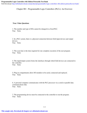
Basic Architecture of PLCProgrammable Logic ControllerSensorsPushbutton switchesLimit switchesInputsMain ProcessingUnit (MPU)OutputsSolenoidsRelay coilsIndicator lightsAlarms,etcProgramming UnitNUSIA- Programmable Logic Controllers4
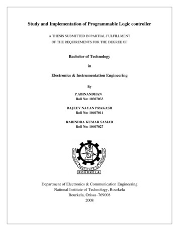
Basic Operation of the PLCThe input program (e.g.ladder diagram) is firstentered and stored inmemory of the InSensorsmicrocomputer.pPushbutton switchesLimit switchesutsProgrammable Logic ControllerMicrocomputerProgramming UnitNUSIA- Programmable Logic ControllersOutputsSolenoidsRelay coilsIndicator lightsAlarms,etcThe CPU then readsthe “program”, e.g.rung by rung of theladder diagram at aconstant samplingfrequency.5
Basic Operation of the PLCThe affected output isthen changed accordingly.Programmable Logic ControllerSensorsPushbutton switchesLimit switchesInputsThe process repeatsuntil the whole ladderis processed from topto bottom. Theprogram then repeatsagain from the toprung.NUSMicrocomputerOutputsSolenoidsRelay coilsIndicator lightsAlarms,etcFor each “rung” of the ladder, theCPU reads the states of thenecessary inputs and, togetherwith the states of any internalProgrammingUnit“relays”,determines the state ofthe affected output.IA- Programmable Logic Controllers6
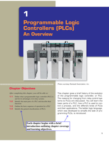
A typical commercial PLCNUSIA- Programmable Logic Controllers7
Typical PLC SpecificationsNUSIA- Programmable Logic Controllers8
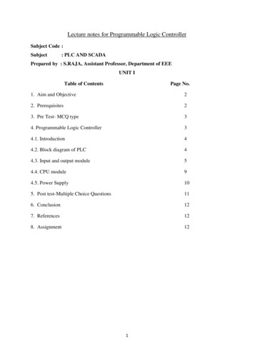
Typical Input Interface CircuitTo detect state of sensors, switches, etc.NUSIA- Programmable Logic Controllers9
Typical Output Interface CircuitTo translate low voltage/current signals to large current,high voltage outputs.NUSIA- Programmable Logic Controllers10
Programming the PLCVarious methods available.Varies from manufacturer to manufacturer.Done directly through a programming unit or througha connection to a PC, depending upon the PLCused.Actual programming is a relatively easy process.The difficult part is deriving the logic, or ladderdiagram, required.NUSIA- Programmable Logic Controllers11
Programming the PLC ladder-diagram based–– carry-over from the popular ladder diagram approach usedin the past and familiar to many automation engineersladder diagram or Boolean expressions of all logic functionfirst derived and “program” input via graphical means oftext editor.Instruction List (mnemonics)– NUSLow level language similar to assembly language codes.Others: sequential function chart (SFC), function blockdiagram (FBD),structured text (ST).IA- Programmable Logic Controllers12
Programming the PLC(based on Mitsubishi)Basic DevicesXn:––––Reserved for physical input devices, e.g. limit switches,pushbuttons, sensors, connected directly to inputs of PLC.Number n available limited depending upon PLC used.State of contacts corresponds directly to the physical inputconnection to the PLC.Any number of contacts available for program.Yn:–––NUSReserved for physical output device, e.g. relays, solenoids,motors, connected directly to outputs of PLC.Number n available is limited depending upon PLC used.These are also implemented as “software” relays with manycontacts.IA- Programmable Logic Controllers13
Programming the PLC(based on Mitsubishi)Basic DevicesTn:–internal “software” timers used for generating timedelays. Number n almost unlimited.Mn:–internal auxiliary “software” relays which comprisesa coil and contacts. Number n almost unlimited.Cn:–NUSinternal “software” counters for counting events.Number n almost unlimited.IA- Programmable Logic Controllers14
Preparing for the Program USThe originalladder diagramInput-OutputassignmentsSol aIA- Programmable Logic Controllers15
Preparing for the Program nputModuleX7Equivalent PLC ladderdiagramSol aIA- Programmable Logic Controllers16
A Sample Programming LanguageX8X7X9Y3Y3NUS0LDX71OR Y32ANI X83ANI X94OUT Y35ENDIA- Programmable Logic ControllersLadderDiagramProgram17
Mnemonic Instructions (based on )FunctionInitial logical operation– NO contactsFigureDevicesExampleX,Y,T,M,CLD X3Initial logical operation– NC contactsX,Y,T,M,CLDI X3Final logical operation- connects to right railY,T,M,COUT Y3The LD and LDI instruction initiates a new logical block. Y,T,M,Cwould be contacts associated with the respective devices.OUT connects output device to right hand rail or bus bar. Cannotbe used with X input devices. Multiple parallel connectionsallowed.NUSIA- Programmable Logic Controllers18
Mnemonic Instructions (LD, LDI, OUT)X0T0T0Y1M100NUSLDOUTLDIOUTOUTENDIA- Programmable Logic ControllersX0T0 K19T0Y1M10019x100msec19
Mnemonic Instructions OR)ORI(ORInverse)NUSFunctionSerial connection– NO contactsFigureDevicesExampleX,Y,T,M,CAND X 3Serial connection– NC contactsX,Y,T,M,CANI Y 3Parallel connection– NO contactsX,Y,T,M,COR M 3Parallel connection– NC contactsX,Y,T,M,CORI X 3IA- Programmable Logic Controllers20
Mnemonic Instructions (AND,ANI,OR,ORI)Y1X0M100X1Y2X3M100Y1Y1X0NUSIA- Programmable Logic 0Y2X3Y1M100X0Y121
Mnemonic Instructions (ORB,ANB)MnemonicFunctionFigureParallel connection ofORB(OR block) multiple serial circuitsANB(ANDblock)NUSSerial connection ofmultiple parallelcircuitsIA- Programmable Logic ControllersExampleORBANB22
Mnemonic Instructions (ORB,ANB)X1X2X3Y1X3X4X5X6Y1NUSIA- Programmable Logic X4X5X6Y7Y123
Mnemonic Instructions (MPS,MRD,MPP)MnemonicFunctionMPS(PointStore)Stores current resultMRD(Read)Reads current resultFigureMPSExampleMPSMRDMRDMPP(Pop)NUSPops (reads andremoves) currentlystored resultMPPIA- Programmable Logic ControllersMPP24
Mnemonic Instructions (MPS,MRD,MPP)X1X2M2M3Y1Y1Y1Y2Y1Y3Y2Y1M2M2M3NUSIA- Programmable Logic M325
Mnemonic Instructions (END)MnemonicFunctionENDForces current programscan to end.FigureEND END forces program to end current scan andrestart a new scan. Useful for debugging purposes as instructionsafter END are ignored.NUSIA- Programmable Logic Controllers26
Timers X1T1K235LdOUTLdOUTT1Y12.35sX1Y1NUS“Software” timers are normallyavailable in PLCs. In the MitsubishiPLC, there are 1msec, 10msec and100msec timers. These have timer“Coils” and “Contacts”. X1T100 K235T1Y1If T1 is a 10msec timer, then relayY1 will turn on after 2.35 sec afterX1 closes and remains closed. Atany time X1 opens, T1 resets.IA- Programmable Logic Controllers27
CountersX1RST C0X2C0K5Ld X1RST C0Ld X2OUT C0 K5Ld C0OUT Y1C0Y1X1X2Y1NUSClosure of X1 resets the counter C0.C0 counts up each time its coil isturned ON by X2. Its output contactsare activated when its coil is turnedON for the fifth time. Thereafter itscount value does not change and itsoutputs remain ON until it is reset tozero X1 closing.IA- Programmable Logic Controllers28
Program ScanProgram Scan:A single processing of the loaded program from start toEND. The process is continuous and once one scanends, a new one is started.Scan Time:Time period for one scan, dependent upon programlength and complexity.Input/Output updating:In some PLCs, all physical inputs are updated at thebeginning of the scan and all physical outputs updatedat the end of the scan.NUSIA- Programmable Logic Controllers29
Program Scan – Double coilingDouble coiling, orspecifying the sameoutput twice, isallowed.X1Y1Y1Y2X2In figure, if X1 ONand X2 OFF, thenY2 ON and Y1 OFF.NUSIA- Programmable Logic ControllersY130
Differences between Relay and PLC ladder diagramsFor PLCRelay circuitHardware components, relaysand other switches, have alimited number of contacts.NUSSoftware components,internal relays, inputs andoutputs, have a “unlimited”number of contacts. No needto try to “save”. Better tomake program easier to read.IA- Programmable Logic Controllers31
Differences between Relay and PLC ladder diagramsFor PLCRelay circuitCurrent flow can take placein any direction .“Current flow" takes placeonly in one direction, fromleft to right.X2X3Y2X5X4Sneak pathX8Y3This ladder diagram will need to bemodified for PLC implementation.NUSIA- Programmable Logic Controllers32
Differences between Relay and PLC ladder diagramsRelay circuitFor PLCContacts cannot be placedvertically , with crossoverlines.Ladder diagrams are strictlytwo-dimensional and therecan be no crossover lines.X1X3Y2X1X3Y2X2X5 X4X2X4X1X5X4X2X5X3Relay circuit. Will needto be modified for PLC.Equivalent PLC circuitNUSIA- Programmable Logic Controllers33
Differences between Relay and PLC ladder diagramsRelay circuitFor PLCAll rungs of the ladderdiagram are activesimultaneously. This"parallel" operationsometimes causes "race"problems and malfunctions .Each rung of the ladder isscanned, and acted upon,successively starting from thefirst rung. When the last runghas been scanned, a newcycle begins from the firstrung again. Scanning periodof the order of 5 to 50 msThe order in which therungs are drawn isimmaterial.NUSThe order in which therungs are "programmed" intomemory is very important.IA- Programmable Logic Controllers34
Program Scan – Program orderFor the PLC, the order in which the rungs are"programmed" into memory is very important.One output pulse for everypositive transition of X3NUSIA- Programmable Logic ControllersY2 always OFF35
An Examplea 1R3RInputModule2R2RC 1ROriginal Ladder diagramM1ConnectedtoB d b X3OutputModuleX3a X4b X5d Y12B Y13C I/O allocationM3M2M2X5Y12X4Y13Re-drawn Ladder diagramFor PLCM1NUSIA- Programmable Logic Controllers36
An ExampleX3M1M3M2Cannot 2X5Y12M2M2 (X3.M1 M2).M3’X4Y13M1NUSIA- Programmable Logic Controllers37
An ExampleProgramX3M1M3M2M2X5Y12M2X4Y13M1NUSIA- Programmable Logic 3M2X5Y12M2X4M1Y1338
End of PLCNUSIA- Programmable Logic Controllers39
IA- Programmable Logic Controllers 6 NUS Microcomputer I n p u t s O u t p u t s Sensors Pushbutton switches Limit switches Solenoids Relay coils Indicator lights Alarms,etc Programming Unit Programmable Logic Controller For each "rung" of the ladder, the CPU reads the states of the necessary inputs and, together with the states of any internal