Transcription
Chapter 21: RLC CircuitsPHY2054: Chapter 211
Voltage and Current in RLC CircuitsÎACemf source: “driving frequency” fε ε m sin ωtÎIfcircuit contains only R emf source, current is simplei ÎIfεR I m sin (ωt )Im εmR( current amplitude )L and/or C present, current is not in phase with emfi I m sin (ωt φ )ÎZ,ω 2π fIm εmZφ shown laterPHY2054: Chapter 212
AC Source and Resistor OnlyÎDrivingvoltage is ε ε m sin ωtiÎRelationof current and voltagei ε /Ri I m sin ωt CurrentIm εmε RRis in phase with voltage (φ 0)PHY2054: Chapter 213
AC Source and Capacitor Onlyq ε m sin ωtÎVoltage is vC CÎDifferentiate to find currentq Cε m sin ωtii dq / dt ωCVC cos ωtÎRewriteusing phase (check this!)i ωCVC sin (ωt 90 )ÎRelationε Cof current and voltagei I m sin (ωt 90 ) I m ΓCapacitive CurrentεmXC( X C 1/ ωC )reactance”: X C 1/ ωC“leads” voltage by 90 PHY2054: Chapter 214
AC Source and Inductor OnlyÎVoltageis vL Ldi / dt ε m sin ωtÎIntegratedi/dt to find current:idi / dt ( ε m / L ) sin ωti ( ε m / ω L ) cos ωtÎRewriteusing phase (check this!)i ( ε m / ω L ) sin (ωt 90 )ÎRelationε Lof current and voltagei I m sin (ωt 90 ) I m ΓInductive CurrentεmXL( X L ωL)reactance”: X L ω L“lags” voltage by 90 PHY2054: Chapter 215
General Solution for RLC CircuitÎWeassume steady state solution of form i I m sin (ωt φ ) Imis current amplitude φ is phase by which current “lags” the driving EMF Must determine Im and φin solution: differentiate & integrate sin(ωt-φ)i I m sin (ωt φ )ÎPlugdi ω I m cos (ωt φ )dtImq cos (ωt φ )SubstituteLdiq Ri ε m sin ω tdtCωI mω L cos (ωt φ ) I m R sin (ωt φ ) Imcos (ωt φ ) ε m sin ωtωCPHY2054: Chapter 216
General Solution for RLC Circuit (2)I mω L cos (ωt φ ) I m R sin (ωt φ ) ÎExpandImcos (ωt φ ) ε m sin ωtωCsin & cos expressionssin (ωt φ ) sin ωt cos φ cos ωt sin φcos (ωt φ ) cos ωt cos φ sin ωt sin φÎCollectsinωt & cosωt terms separately(ω L 1/ ωC ) cos φ R sin φ 0I m (ω L 1/ ωC ) sin φ I m R cos φ ε mÎTheseHigh school trig!cosωt termssinωt termsequations can be solved for Im and φ (next slide)PHY2054: Chapter 217
General Solution for RLC Circuit (3)ÎSolvefor φ and Imtan φ ÎR,ω L 1/ ωCRX L XC RIm εmZXL, XC and Z have dimensions of resistanceX L ωLInductive “reactance”X C 1/ ωCCapacitive “reactance”Z R2 ( X L X C )ÎThis2Total “impedance”is where φ, XL, XC and Z come from!PHY2054: Chapter 218
Im AC Source and RLC CircuitsεmMaximum currentZX L XCtan φ RX L ωLPhase angle(ω 2π f )X C 1/ ωCZ R2 ( X L X C )Inductive reactanceCapacitive reactance2Total impedanceφ angle that current “lags” applied voltagePHY2054: Chapter 219
What is Reactance?Think of it as a frequency-dependent resistance1XC ωCShrinks with increasing ωX L ωLGrows with increasing ω( "XR " R )Independent of ωPHY2054: Chapter 2110
Pictorial Understanding of ReactanceZ R2 ( X L X C )2X L XCtan φ RRcos φ ZPHY2054: Chapter 2111
Summary of Circuit Elements, Impedance, Phase AnglesZ R2 ( X L X C )2PHY2054: Chapter 21X L XCtan φ R12
QuizÎThreeidentical EMF sources are hooked to a single circuitelement, a resistor, a capacitor, or an inductor. Thecurrent amplitude is then measured as a function offrequency. Which one of the following curves correspondsto an inductive circuit? (1)a (2) b (3) c (4) Can’t tell without more infoaImaxbcX L ωL(ω 2π f )I max ε max / X LfFor inductor, higher frequency gives higherreactance, therefore lower currentPHY2054: Chapter 2113
RLC Example 1ÎBeloware shown the driving emf and current vs time ofan RLC circuit. We can conclude the following Current“leads” the driving emf (φ 0) Circuit is capacitive (XC XL)IεtPHY2054: Chapter 2114
RLC Example 2ÎR 200Ω, C 15μF, L 230mH, εmax 36v, f 60 Hz X L 2π 60 0.23 86.7Ω X C 1/ 2π 60 15 10 6 177Ω Z 2002 ( 86.7 177 ) 219Ω I max ε max / Z 36 / 219 0.164 A ()XC XLCapacitive circuit2 1 86.7 177 φ tan 200 24.3 Current leads emf(as expected)i 0.164sin (ωt 24.3 )PHY2054: Chapter 2115
ResonanceÎConsiderimpedance vs frequencyZ R ( X L X C ) R (ω L 1/ ωC )2ÎZ222is minimum when ω L 1/ ωC ω ω0 1/ LC ThisÎAtis resonance!resonance Impedance Z is minimum Current amplitude Im is maximumPHY2054: Chapter 2116
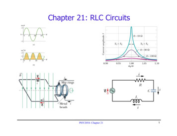
Imax vs Frequency and ResonanceÎCircuitparameters: C 2.5μF, L 4mH, εmax 10v f0 1 / 2π(LC)1/2 1590 Hz Plot Imax vs fI max 10 / R (ω L 1/ ωC )22R 5ΩR 10ΩImaxR 20ΩResonancef f0f / f0PHY2054: Chapter 2117
Power in AC CircuitsÎInstantaneouspower emitted by circuit: P i2RP I m2 R sin 2 (ωd t φ )ÎMoreInstantaneous power oscillatesuseful to calculate power averaged over a cycle Use to indicate average over a cycleP I m2 R sin 2 (ω d t φ ) 12 I m2 RÎDefineRMS quantities to avoid ½ factors in AC circuitsI rms ÎHouse VrmsIm2ε rms εm22Pave I rmsRcurrent 110V Vpeak 156VPHY2054: Chapter 2118
Power in AC CircuitsÎPowerformulaÎRewrite2Pave I rmsR I rms I max / 2using I rms ε rmsPave ε rms I rms cos φPave Zε rmsRcos φ ZZI rms R ε rms I rms cos φZφX L XCRÎcosφis the “power factor”maximize power delivered to circuit make φ close to zero Max power delivered to load happens at resonance E.g., too much inductive reactance (XL) can be cancelled byincreasing XC (e.g., circuits with large motors) ToPHY2054: Chapter 2119
Power Example 1ÎR 200Ω, XC 150Ω, XL 80Ω, εrms 120v, f 60 Hz Z 200 ( 80 150 ) 211.9Ω I rms ε rms / Z 120 / 211.9 0.566 A 22 1 80 150 φ tan 19.3 Current leads emfCapacitive circuit 200cos φ 0.944 Pave ε rms I rms cos φ 120 0.566 0.944 64.1W Same2Pave I rmsR 0.5662 200 64.1WPHY2054: Chapter 2120
Power Example 1 (cont)ÎR 200Ω, XC 150Ω, XL 80Ω, εrms 120v, f 60 HzÎHowmuch capacitance must be added to maximize thepower in the circuit (and thus bring it into resonance)? WantXC XL to minimize Z, so must decrease XC X C 150Ω 1/ 2π fCC 17.7μF X C new X L 80ΩCnew 33.2μF So we must add 15.5μF capacitance to maximize powerPHY2054: Chapter 2121
Power vs Frequency and ResonanceÎCircuitparameters: C 2.5μF, L 4mH, εmax 10v f0 1 / 2π(LC)1/2 1590 Hz Plot Pave vs f for different R valuesR 2ΩR 5ΩPaveR 10ΩResonanceR 20Ωf f0f / f0PHY2054: Chapter 2122
Resonance Tuner is Based on ResonanceVary C to set resonance frequency to 103.7 (ugh!)Other radio stations.RLC response is lessCircuit response Q 500Tune for f 103.7 MHzPHY2054: Chapter 2123
QuizÎAgenerator produces current at a frequency of 60 Hz withpeak voltage and current amplitudes of 100V and 10A,respectively. What is the average power produced if theyare in phase? (1) (2) (3) (4) (5)1000 W707 W1414 W500 W250 WPave 12 ε peak I peak ε rms I rmsPHY2054: Chapter 2124
QuizÎThefigure shows the current and emf of a series RLCcircuit. To increase the rate at which power is delivered tothe resistive load, which option should be taken? (1)Increase R (2) Decrease L (3) Increase L (4) Increase CX L XCtan φ RCurrent lags applied emf (φ 0), thus circuit is inductive. Either(1) Reduce XL by decreasing L or(2) Cancel XL by increasing XC (decrease C).PHY2054: Chapter 2125
Example: LR Circuitfrequency EMF source with εm 6V connected to aresistor and inductor. R 80Ω and L 40mH.ÎVariable Atwhat frequency f does VR VL?X L ω L R ω 2000 Atf 2000 / 2π 318Hzthat frequency, what is phase angle φ?tan φ X L / R 1 φ 45 Whatis the current amplitude and RMS value?I max ε max / 802 802 6 /113 0.053AI rms I max / 2 0.037 Ai 0.053sin (ωt 45 )PHY2054: Chapter 2126
TransformersÎPurpose:change alternating (AC) voltage to a bigger (orsmaller) valueInput AC voltagein the “primary”turns produces a fluxVp N pChanging flux in“secondary” turnsinduces an emfΔΦ BVs N sΔtΔΦ BΔtNsVs V pNpPHY2054: Chapter 2127
TransformersÎNothingcomes for free, however! Increasein voltage comes at the cost of current. Output power cannot exceed input power! power in power out (Losses usually account for 10-20%)i pVp isVsis V p N p i p Vs N sPHY2054: Chapter 2128
Transformers: Sample ProblemÎAtransformer has 330 primary turns and 1240 secondaryturns. The input voltage is 120 V and the output currentis 15.0 A. What is the output voltage and input current?Ns 1240 Vs V p 120 451VNp 330 i pV p isVs“Step-up”transformerVs 451 i p is 15 56.4 AVp 120 PHY2054: Chapter 2129
Transformers¾ This is how first experiment byFaraday was done¾ He only got a deflection of thegalvanometer when the switchis opened or closed¾ Steady current does not makeinduced emf.PHY2054: Chapter 2130
ApplicationsMicrophoneTape recorderPHY2054: Chapter 2131
ConcepTest: Power linesÎAtlarge distances, the resistance of power lines becomessignificant. To transmit maximum power, is it better totransmit (high V, low i) or (high i, low V)? (1)high V, low i (2) low V, high i (3) makes no differencePower loss is i2RPHY2054: Chapter 2132
Electric Power Transmissioni2R: 20x smaller current 400x smaller power lossPHY2054: Chapter 2133
PHY2054: Chapter 21 19 Power in AC Circuits ÎPower formula ÎRewrite using Îcosφis the "power factor" To maximize power delivered to circuit make φclose to zero Max power delivered to load happens at resonance E.g., too much inductive reactance (X L) can be cancelled by increasing X C (e.g., circuits with large motors) 2 P ave rms IR rms ave rms rms rms cos


