Transcription
Wireline BasicIndex1FACILITY SAFETY1.123RULES AND REGULATIONS1.1.1 Classroom House Rules1.1.2 Workshop and Well Site Rules1.1.3 Course Rules1.1.4 Fire PlanORIGINS OF OIL AND GAS2.1INTRODUCTION2.2COMMERCIAL OIL FIELDS2.3RESERVIOR DRIVE MECHANISMS2.3.1 Internal Drive2.3.2 Depletion Drive2.3.3 External Gas Cap2.3.4 Water Drive2.3.5 External DriveCOMPLETION DESIGN3.1INTRODUCTION3.2WIRELINE RE-ENTRY GUIDE3.3TUBING PROTECTION JOINT3.4NO-GO LANDING NIPPLE3.5PERFORATED PUP JOINT3.6LANDING NIPPLE3.7PUP JOINT3.8CROSSOVER3.9MILLOUT EXTENSION3.10 PACKER3.11 POLISHED BORE RECEPTACLE (PBR)3.12 TUBING LANDING NIPPLE3.13 SIDE POCK MANDREL3.14 MID-TUBING LANDING NIPPLE3.15 FLOW COUPLING3.16 SAFETY VALVE LANDING NIPPLE3.17 TUBING3.18 CONTROL LINE3.19 TUBING HANGER
Wireline Basic4XMAS TREES4.1INTRODUCTION4.2VALVES4.2.1 Lower Master Valve (LMV)4.2.2 Upper Master Valve (UMV)4.2.3 Flow Wing Valve (FWV)4.2.4 Kill Wing Valve (KWV)4.2.5 Choke Valve4.2.6 Swab Valve4.2.7 Tree Cap5WHAT IS WIRELINE?5.1INTRODUCTION5.2BENDING STRESSES5.3RE-SPOOLING5.4HANDLING AND STORAGE5.5GENERAL SAFETY PRECAUTIONS5.6WIRELINE TORSION TESTER5.6.1 Objective5.6.2 Procedure5.6.3 Slickline Operation And Maintenance5.6.4 Torsion Test Specimen Configuration5.7WIRELINE TEST ANALYSIS5.7.1 Acceptance5.7.2 Torsion Fracture Analysis5.7.3 Fracture Classification5.7.4 General Guidance NotesWireline Basic
6QUICK UNIONS6.1INTRODUCTION6.1.1 Wellhead Adaptor (Tree Adaptor)6.1.2 Pump-In Tee6.1.3 Wireline Blow Out Preventor (BOP)6.1.4 Pressure Testing of BOP6.1.5 Lubricators6.1.6 Injection Sub6.1.7 Cutter Valve6.1.8 Workover Valve6.1.9 Stuffing Box6.1.10 Hydraulic Packing Nut7WIRELINE UNIT7.1HAY PULLEY AND WEIGHT INDICATOR7.2HAY PULLEY7.3WEIGHT INDICATOR7.3.1 Introduction7.4COUNTER HEAD7.5CAUSES FOR DEPTH DISCREPANCIES7.5.1 Wireline Angle Correction Factors7.6WIRELINE CLAMP8POWER PACKS8.1ELECTRICAL8.2DIESEL8.2.1 Fault Finding Chart9WELL CONTROL PANEL AND B.O.P PUMPS9.1WELL CONTROL PANEL9.2OPERATING PROCEDURES9.2.1 Pre-Operational Checks9.2.2 Routine Operating ProceduresWireline Basic
10GENERAL TOOLSTRING10.1 PRIMARY EQUIPMENT10.1.1 Rope Sockets10.1.2 Stem Types10.1.3 Knuckle Joints10.1.4 Power Jars10.1.5 Mechanical Jars10.1.6 Accelerators/ Stretch Simulators10.1.7 Quick Lock System11NON-SETTING WIRELINE TOOLS13.1 GAUGE CUTTER13.2 LEAD IMPRESSION BLOCK13.3 BLIND BOX13.4 TUBING END LOCATOR13.5 BAILERS13.5.1 Pump Bailer13.5.2 Drive Down Bailer13.5.3 Hydrostatic Bailer12BASIC PULLING TOOLS12.112.2FISHING NECK IDENTIFICATION / EXTERNAL / INTERNALREACH12.1.1 Selection of Shear DirectionBASIC PULLING TOOLS12.2.1 ‘S’ Series Pulling Tool (Shear Down To Release)12.2.2 ‘R’ Series Pulling Tool (Shear Up To Release)12.2.3 ‘JD’ Series Pulling Tool (Shear Down To Release)12.2.4 ‘JU’ Series Pulling Tool (Shear Up To Release)12.2.5 ‘GS’ Series Pulling Tool (Shear Down To Release)12.2.6 ‘GR’ Series Pulling Tool (Shear Up To Release)12.2.7 ‘PRS’ Series Pulling Tool (Shear Down To Release)
13EXERCISES13.1WIRELINE PROGAMME13.1.1 Wireline PCE and toolstring preparation13.1.2 Programme Objectives13.1.3 Programme Execution13.1.4 Lessons Learned
1FACILITY SAFETY1.1RULES AND REGULATIONS1.1.1Classroom House Rulesa)b)Starting time will be 09:00 and finishing time 16:30, Monday through Friday. Coffee Breaks Lunch break will be 30 minutes or at the instructor's discretion.All materials, handouts etc. will be collected and left tidy on your desk at the end ofeach day. c)- 15 minutes in the morning.- 15 minutes in the afternoon, depending on workload.Empty coffee cups and rubbish must be disposed in the bins provided.A sensible dress code will be expected while working in the classroom.
1.1.2Workshop Or Well Site Rulesa)LockersLockers will be provided for all students during the course. The locker will be yourpersonal responsibility and kept clean and tidy. Also keep the changing room tidy.b)WellsiteWe must assume the work area is a pipe deck offshore and respect it the same manner. All equipment must be rigged up and laid out neatly.All oil or diesel spillage must be mopped up immediately using the oil spillgranules or cleaning fluids provided.After rigging down the unit, the workbench and tools must be cleaned andreturned to the appropriate storage place and left as you would expect to find it.c)All downhole tools used will be stripped, cleaned and redressed, if necessary, readyfor the next class.d)When outside on the Training Well you will always wear the following: e)Hard HatSafety BootsCoverallsSafety GlassesGlovesHearing Protection as requiredEquipment operating signalsThere are a number of signals that must be learnt know in order to acknowledge properfunctioning and movement of the wireline equipment. These signals will be demonstratedto you and must be used at all times when working with the wireline unit.f)Safety harnessAs offshore, all students must wear a safety harness while working any more than 1.5metres off the ground. While rigging the equipment up or down these safety harnesses will beprovided and will be used.
1.1.3Course Rules1)2)3)4)5)6)7)8)9)10)11)Personnel safety is paramount. Always wear Personal Protective Equipment (PPE)when working outside, in the workshop or wellhead areas.Report all accidents or incidents to your instructor, no matter how trivial they mayseem at the time. Seek medical aid if required. If accidents are not reported,appropriate actions cannot be implemented to prevent similar future occurrences.No alcohol is to be consumed in the training centre, unless authorised for special nontraining occasions. Any student found under the influence of alcohol will beimmediately expelled from the class and reported to his immediate line manager.Full effort by students is expected on all courses.Random alcohol and/or substance abuse test may be carried out during the term ofthe course.PPE and dirty clothes/shoes shall not be worn inside the building i.e. classroom,recreation area, office, etc.As you are not the only students using the facility, please show respect for others.No foul language and no obscene materials are allowed.Good housekeeping is required everywhere, including the locker facilities and toilets.You are expected to be in class by 09.00 am each day and you will be allowed coffeeand lunch breaks at the set times. Your course instructor will advise you of thesetimes.The course register must be filled in each day. The register keeper should deliver itto the training secretary by 08.45 am.PSL Energy Services operate a no smoking policy within the training centre, howevera designated smoking area is provided for delegates.SIGNEDDATE
2ORIGINS OF OIL AND GAS2.1INTRODUCTIONPetroleum (derived from the Greek ‘Petra’ for rock and the Latin ‘Oleum’ for oil) isobtained from the fluids contained in underground reservoirs.The hydrocarbons contained in these fluids have had their origins in the residues of plantand animal life, which were washed into sedimentary basins and buried through time.Subjected to abnormal temperature and pressure gradients, the fats and proteins in theseresidues are probably decomposed aerobically (without oxygen) in the source rock to formthe hydrocarbons known generically as gas, condensate, or black oil.The formation of these hydrocarbons is invariably accompanied by volume changes withhigh increases in local pressure. These pressure increases probably initiate micro fracturesin the sedimentary rock, thereby allowing the hydrocarbons to migrate along potentialgradients until they surfaced, or were caught in traps.Most traps are structural anticline or fault traps, which are common to the majority ofsedimentary basins. Three-dimensional containment is established by an impermeable sealabove, around the sides, and by the buoyancy of the hydrocarbons on underlying water.This section contains a discussion of the Organic Theory of Petroleum, which is the widelyaccepted version by the scientific world, with a brief overview of geological structureswhich form petroleum reservoirs.2.2COMMERCIAL OIL FIELDSIn order for an oil and gas field to exist, four basic conditions must have been met: A source from which hydrocarbons originated, with suitable environmentalconditions that changed the source material into petroleumA porous rock bed laid down, through which the petroleum could migrate to itsreservoir rock.A suitably shaped trap formed under which the petroleum accumulatedAn impervious cap or seal rock overlaid causing the trap.To ensure that a field is commercially viable, the reservoir rock must in addition exhibitthree further essential characteristics: Continuity between pore spaces or permeability. There must be some degree ofcontinuity between void spaces so that reservoir fluids can flow through longdistances under very small pressure gradientsHydrocarbons must be of low enough molecular weight and, therefore,viscosity to allow flow to occur.Must have an organic content greater than 1% (the organic content of typicalNorth Sea hydrocarbon-bearing rock exceeds 7%).
2.3RESERVOIR DRIVE MECHANISMSIdeally in an offshore oil field, the hydrocarbons are recovered from the reservoir porespaces by exploiting a drive mechanism, precluding the need for artificial methods. Drivemechanisms have two classifications: 2.3.1Internal drive using the internal energy of the reservoir configurationExternal drive, which involves the invasion of the pore spaces by a replacementfluid.Internal DriveThis is known as primary recovery, which includes three drive mechanisms: 2.3.2Depletion or internal gas drive.External gas cap drive.Water drive.Depletion DriveThe compressibility of oil and water is relatively small. As soon as production commences,it is accompanied by a rapid drop of pressure in the producing zone which soon reaches thebubble point of entrained gas. See Error! Reference source not found. Initially, this gasis dispersed, but it rapidly expands and assists in dispelling the oil. Eventually, however,the gas will start to form a gas front, which, having more mobility than the oil, andincreases the production gas/oil ratios. This depletion or internal gas drive is characterisedby a rapid decline in reservoir pressure and by the recovery of only a small percentage ofthe oil in situation of 5 to 20 % maximum.2.3.3External Gas CapWhere the oil has a gas cap, the gas cap pressure together with the pressure of gas insolution tends to maintain pressure in the reservoir much longer than depletion drive. SeeError! Reference source not found. Therefore gas cap reservoirs have higher recoveryrates of (20 to 40%).2.3.4Water DriveWater drive is characterised by large local deposits of water which expand as pressure isreduced in the reservoir see Error! Reference source not found. Eventually, recoverywill decrease due to the greater mobility of the water front which eventually breaks throughto the wellbore with increasing water/oil ratios. Nonetheless, water drive is the mostefficient of the drive mechanisms and can produce recovery rates as high as 60 %.All three drive mechanisms may be present to varying degrees at the same time althoughone will be predominant.
2.3.5External DriveIf a fluid is injected into a well so that the volumetric rate of fluid replacement is equal tothe volumetric rate of fluid extraction, then the average reservoir pressure will tend toremain constant. Injection stimulates secondary recovery.Depending on the type and configuration of the reservoir, pressure can be maintainedtherefore by: Gas injectionWater injectionMiscible and immiscible fluid injection.In general, gas is injected into the crest, and water injection into the base or periphery ofthe reservoir. Particular consideration must be given to the quality of the injection fluids,compatible with existing reservoir fluids, filtered to prevent formation plugging, viscosewhich should be significantly higher than formation water, variations in reservoirpermeability, and injection rate. If the injection rate is excessive, the water front mayadvance unevenly, thus giving rise to early water breakthrough, or to unstable coning
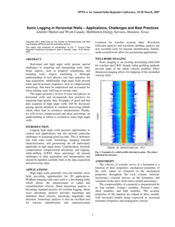
3COMPLETION DESIGN3.1INTRODUCTIONThe example completion selected (refer to Error! Reference source not found.), is anexample of a simple and versatile design.The equipment used in this completion is in common use and the specific applications anduses are outlined in the sub-sections below.Starting with item 25, on the completion schematic (which is the first item to be run in thehole), there follows a brief description of the use and position of each item of equipment inthe string.3.2WIRELINE RE-ENTRY GUIDE(Refer to Item 25 on the diagram.)This guide, sometimes abbreviated to WEG, is generally available in two forms.g)Bell GuideThis guide has a 45 lead-in taper to allow easy re-entry of wireline tools into the tubingstrings. This guide is used in a completion where the end of the tubing does not need toenter the top of liner hanger or packer tops.h)Mule Shoe Re-EntryThis guide is essentially the same as a bell guide, but modified by having a large 45 anglecut across from the outside of the guide. The 45 shoulder when orientated by turning thetubing enables the guide to enter liner tops.3.3TUBING PROTECTION JOINT(Item 24)This is a single joint of tubing, included for the particular purpose of protectingpressure/temperature gauges that may be suspended from the landing nipple immediatelyabove.3.4NO-GO LANDING NIPPLE(Item 23)This nipple is used exclusively for the installation of wireline set gauge hangers.
Figure 3.1 - Typical Completion Schematic3.5PERFORATED PUP JOINT
(Item 22)In wells having large flow volumes, a restriction in the tubing such as a gauge hanger, willcause false pressure recordings. Vibration due to flow turbulence may also cause extensivedamage to the gauges, therefore a perforated pup joint (approx. 10 ft long) is installedabove the gauge hanger nipple. This allows flow to pass unrestricted around the gauges andhanger, providing accurate pressure/temperature recordings within the limits of the gauge.The total area of the perforations must be greater than the ID of the pup joint (generally 3-4times the area).3.6LANDING NIPPLE(Item 21)This nipple is the primary plugging point below the packer, it is used during the initialcompletion stage as a receptacle for a ‘test tool’. A test tool is run into a no-go nipple andseats against the no-go shoulder, it does not lock into the nipple. The test tool packingscreate a seal within the seal bore of the nipple and will hold pressure from above only. Itshould hold sufficient pressure to enable the setting of the hydraulic packer, and then testthe tubing.After its initial use as described above, the nipple is used for well plugging by installing theappropriate type plug (e.g. when tubing above the packer has to be pulled leaving thepacker in the hole).3.7PUP JOINT(Item 20)Used for spacing out tubing or as a handling joint when completion equipment is made upinto sub-assemblies for ease of handling and quick completion installation.3.8CROSSOVER(Item 19)A crossover is a connector which fits between two different sizes or types of threadedconnections. For instance between 4 ½” to 5 ½” or 3 ½” to 4 ½” tubing, etc.3.9MILLOUT EXTENSION(Item 18)This is generally a pup joint with a slightly larger ID than the packer bore and provides ashoulder onto which a packer-plucker can latch during packing/milling operations. Thisenables the packer and tail-pipe assembly to be retrieved during the same run as the millingoperation.
3.10PACKER(Item 17)The packer in the example is a hydraulic type set permanent packer, which is installed onthe production string. It isolates the producing zone from the tubing/casing annulus. Thisprotects the production casing from well pressure and corrosive fluids maintaining itsintegrity over the life of the well.3.11POLISHED BORE RECEPTACLE (PBR)(Item 16)The seal receptacle is attached to the top of the packer. The seal assembly, which mateswith the PBR, is attached to the bottom of the tubing string.The function of the PBR is to allow travel upwards and downwards within the PBR to caterfor tubing movement due to expansion or contraction of the tubing caused by flowingconditions or well operations.Sometimes the seals are attached to the PBR with shear-pins or shear-ring in order that thecompletion can be installed in one trip. The shear pins or shear ring can then behydraulically or mechanically sheared to allow travel, after the packer has been set.3.12TUBING LANDING NIPPLE(Item 15)This nipple is used for testing the tubing above the packer. In conjunction with item 21, itcan be used to find if tubing leaks are present above or below the packer.3.13SIDE POCKET MANDREL(With Shear Relief Valve)(Item 14)This can be used as an alternative circulating device to a conventional sliding side door*(SSD), which can incorporate an annulus pressure actuated circulating valve. The valve isoperated by applying pressure to the annulus which is the annular space between the tubingOD and the production casing ID.*The SSD is a circulating device to provide a means of communication between thetubing and annulus. SSD’s are operated by shifting a sleeve to align communicationports. This is done be means of a wireline run tool.
MID-TUBING LANDING NIPPLE(Item 10)This landing nipple would is installed at approx. 3,500 ft and would normally be used forplugging the well if a neighbouring well is being drilled in the immediate vicinity and is tobe ‘kicked off’ or deviated. The kick-off point for deviated wells in the North Sea isgenerally around 2000 ft. If, in the unlikely event, the drill-bit should penetrate the well,the reservoir pressure would be isolated from reaching the drill string by the plug in thenipple.3.14FLOW COUPLING(Item 9)When flowing a high rate well, the fluid will move at extremely high speed. When meetinga restriction, such as a nipple profile, excessive turbulence will develop immediately abovethe nipple causing excessive erosion. To cater for this excessive erosion, a six foot joint ofheavy walled tubing would be installed above (and sometimes below) the nipple. Althoughthe same amount of erosion will be experienced, the added wall thickness of the flowcoupling will leave sufficient material intact to prevent any leakage during the life of thewell.3.15SAFETY VALVE WIRELINE NIPPLE(Item 5)This nipple is designed to accommodate a wireline retrievable safety valve, remotelyoperated from the surface by a hydraulic control line, (Item 4) - See Item 9(Item 3) - See Item 20The other common type of safety valve used is the tubing retrievable type safety valve.This valve is installed as a component of the tubing string and also requires a control linefor operation from surface.3.16TUBING(Item 2)Tubing is the flow conduit for the produced fluids. It is manufactured in lengths, termedjoints, of approximately 30 to 35 feet long.The tubing connects all of the other completion components together from the re-entryguide to surface.
3.17CONTROL LINE(Item 1)This is normally a 1/4 inch OD Monel or stainless steel tubing, connected between thesafety valve nipple (or tubing retrievable valve) and the tubing hanger. The control line issecured to the tubing by clamps (these may be Steel or Plastic). It is the conduit used forthe supply of hydraulic pressure from the surface control panel to the safety valve.3.18TUBING HANGERThe tubing hanger (not shown) supports the weight of the completion string in the wellheadand also seals between the tubing/Xmas tree bore and the annulus.
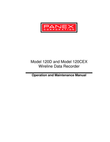
4XMAS TREES4.1INTRODUCTIONA Xmas tree is an assembly of valves and fittings used to control the flow of wellfluids atsurface and to provide access to the production tubing. The Xmas tree is essentially amanifold of valves which is installed as a unit on top of a tubing head upper flange, oradapter flange, of a wellhead; Figure 4.1.4.2VALVESTypically, from bottom to top, a Xmas tree will contain the following valves:4.2.1Lower Master Valve (LMV) Application:Operation:-Utilised in all Xmas trees to close in the wellManual.The master valve, as its name implies, is the most important valve on the Xmas tree. Whenclosed this valve contains well pressure and should only be used for safety and isolationpurposes and never should be used as a working valve.In moderate to high pressure wells, Xmas trees are often provided with two master valves,the upper of which is furnished with a valve actuator system for automatic or remotecontrolled operation (surface safety valve). This is often a regulatory requirement in sour orhigh pressure wells.4.2.2Upper Master Valve (UMV) Application:- Utilised on moderate to high pressure wells as an emergencyshut in system. The valve is sometimes capable of cutting 7/32 inch braidedwireline.Operation:Valve actuated pneumatically or hydraulically.The UMV is a surface safety valve and is normally connected to the emergency shutdown(ESD) system.4.2.3Flow Wing Valve (FWV) Application:- To permit the passage of well fluids to the choke valve.Operation:Manual or automatic (pneumatic/hydraulic) depending onwhether the surface safety system includes the production wing.On moderate to high pressure wells, two production wing valves are installed, one manualand the other equipped with a valve actuator.
Figure 4.1 - Xmas Tree Valve System
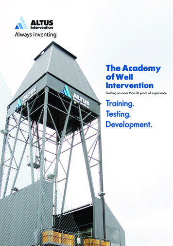
4.2.4Kill Wing Valve Application:- To permit entry of kill fluid into the completion string and alsofor pressure equalisation across tree valves, e.g. during wireline operations orprior to the removal/opening of a sub-surface safety valve.Operation:Manual.Kill fluid is a high density fluid designed to overcome and control formation pressures inthe event of an emergency or, if for any reason it is necessary to remove the Xmas treefrom the wellhead.4.2.5Choke Valve Application:- Utilised to restrict, control or regulate the flow ofhydrocarbons to the production facilities.Operation:Manual or automatic.This valve may be of the fixed or adjustable type. It is the only valve in the Xmas tree thatis used to control flow.NOTE:4.2.6All other valves used on Xmas trees are invariably the gate valve typeproviding full bore access to the well i.e. the valve must be operated in thefully open/fully closed positions.Swab Valve Application:- This permits vertical entry to the well for well interventionsuch as wireline, coiled tubing and snubbing methods.Operation:Manual.The swab valve is the uppermost valve on the Xmas Tree. In combination with a wirelinelubricator, refer to Figure 4.2, it allows the running of wireline tools, instruments, and otherequipment into the well, under pressure.
4.3XMAS TREE CAP Application:Installation:-Provides the appropriate connection for the wireline lubricator.Directly above the swab valve.The Xmas tree cap normally incorporates a quick union-type connection, which should becapable of supporting the lubricator for wireline work. The ID should permit the running ofwireline equipment compatible with the tubing size.CAUTION:NOTE:Always ensure that swab valve is closed and that pressure is fully bledoff before attempting to remove the Xmas tree cap.The Xmas tree should have a rated working pressure greater than theclosed in tubing head pressure of a well.All Xmas tree valves and components must, at minimum, meet API Spec. 6A Specifications for wellhead equipment, which specifies all essential dimensions,pressure/temperature ratings, material properties and composition, and testing procedures.The throughbore of a Xmas tree is specified by API and is generally 1/16 inch larger thanthe tubing ID.
Figure 4.2 - Wireline Surface Equipment
5WHAT IS WIRELINE?5.1INTRODUCTIONThrough all stages of drilling, testing, completion and production, wireline procedures willbe used extensively for work-over, data gathering and operational requirements. Modernwireline techniques and equipment have developed and improved enormously as the wholeoil industry itself has developed.Originally, wireline was conceived as an early method of determining the depth of a wellaccurately, by lowering a flat section, graduated steel tape into the well from a handoperated reel.As depths increased, the difficulties associated with this technique grew until it was nolonger safe or practicable. The tape was replaced by a circular section of slickline ormeasuring line, which allowed superior sealing properties when the survey was performedunder well pressure.The line was marked in equal increments and calibrated measuring wheels introduced.These ‘Veeder Root’ counters are very similar to those in use today. Larger diameter lineswere introduced as new demands on the line, such as removal of deposits, installation andremoval of flow control devices were made. The grade of solid steel line has progressed tothe modern line in use today of 25,000 ft. length and extremely high tensile strength.Downhole equipment was now being designed with the greater wireline capability in mind.This equipment included tubing plugs, to enable the tubing to be run and pulled underpressure, bottom hole chokes for gas wells to prevent freezing of surface flow lines causedby choking at the surface, running straight hole survey instruments, known as ‘sypho’ andoperation of the first regulated gas lift valve, known as the Nixon valve. The Nixon valvewas opened by upward movement of the slickline, controlled at the surface by timingdevices. As the wireline was pulled upward, tools attached to the lower end opened thevalve, allowing the gas to enter the tubing from the annulus. This early method of gas liftoperations was followed by gas lift valves which could be removed and repaired oradjusted and reset by the use of wireline tools.The wireline winch unit has developed from a hand-operated reel or motor, driven from therear axle of a car, to the modern skid-mounted, self-contained module, driven electrically,mechanically or hydraulically and fully equipped with tools and wellhead equipment tosafely service gas or oil wells under pressure.Wireline may be referred to by a number of names. Solid single strand line may bedescribed as: SlicklineWirelineMultistrand wirelines are usually described as braided line.
As well depths have increased over the years since the first measuring lines were broughtinto use, accompanied by increased working loads, it has become necessary to developwireline having a high strength/weight ratio.There is a need for strength to accomplish the operation without the wire breaking, and aneed to keep the diameter of the wire as small as possible for the following reasons: It reduces the load of its own weightIt can be run over smaller diameter sheaves, and wound on smaller diameterspools or reels without overstressing by bendingIt keeps the reel drum size to a minimumIt provides a small cross-section area for operation under pressure.The sizes of solid wireline in most common uses are: 0.108ins and 0.125ins diameter, andare obtainable from the drawing mills in one-piece standard lengths of 18,000, 20,000,25,000 and 30,000 ft.The most popular material for wireline is improved plough steel (IPS), because of its highultimate tensile strength, good ductility, and relatively low cost. Experience indicates thatimproved plough steel usually performs better than the more expensive special steel lines,even in corrosive conditions - although then it must be used with an appropriate inhibitor(e.g. Servo CK352 or CK356). For Sweet Wells IPS can be used with inhibitor for highloads and long service. For Sour Wells IPS can be used with inhibitor for high loads andshort operating time.When selecting or operating with wireline, various factors, such as the following, havebeen considered: Physical propertiesResistance to corrosionEffect of bendingTotal stressCare and handling.Due to the H2S content of many wells special materials such as 0.108 ins NITRONIC-50manufactured by Bridon Wire, or stainless steels are used. Although these are not as strongas IPS, they have an excellent resistance to H2S corrosion.Refer to Expro Wireline Operational Guidelines for further information.
The following table shows the relative strengths of IPS. (Improved Plough Steel) wire andH2S resistant alloy wirelines: General Comparison of Grades.SteelSpecificationsCarbon Steel - BrightDrawn GalvanisedUltra High TensileStainless - 304 Type316 TypeSupa 60Supa 70Supa 75API-9AAPI-9ABridon UHTBridonBridonBridonBridonBridonStrength Relative toAPIAPI-9AAPI-9A25% HigherAPI-9A10% Lower15/20% Lower5% HigherSimilarGeneral CorrosionResistance RatingPoorBetterPoorGoodBetter than 304ExcellentExcellentBetter than Supa 70Table 5.1Carbon Steel Wires to API-9AThe wire is supplied on steel reels in continuous lengths. Diameter tolerance 0.001 inch.Torsion in all cases in accordance with API-9A.NominalDiameterNominal Weightper 1000 inimum PulleyDiains11.2513.0015.00Minimum Breaking LoadBrightlbs154721202840UHT Brightlbf198027203640Table 5.2Stainless Steel and Special AlloysAll stainless steel and Special Alloy wires are supplied on nylon coated steel reels incontinuous lengths, to the following Bridon specifications. Diameter tolerance 0.001 insDuctility wraps on own diameter - 8 tper 1000ftlbs22.9031.5542.26PulleyRec’d304316Supa imum BreakingLoadSupa 70Supa 75Diameterins11.2513.0015.00Table 5.3lbf160021002600lbf147020302526
5.2BENDING STRESSESThe bending stresses that the line is subjected to are the most common cause of breakingbut are generally the least considered. Bending occurs whenever a line deviates from astraight line condition, such as when it passes over pulleys or reel drum, or when it isflexed by hand.It is necessary to employ specific mechanical equipment, such as the reel drum, hay pulley,stuf
11 NON-SETTING WIRELINE TOOLS 13.1 GAUGE CUTTER 13.2 LEAD IMPRESSION BLOCK 13.3 BLIND BOX 13.4 TUBING END LOCATOR 13.5 BAILERS 13.5.1 Pump Bailer 13.5.2 Drive Down Bailer 13.5.3 Hydrostatic Bailer 12 BASIC PULLING TOOLS 12.1 FISHING NECK IDENTIFICATION / EXTERNAL / INTERNAL REACH 12.1.1 Selection of Shear Direction