Transcription
Operating ManualDLS-8235VDSL2 WirelineSimulatorEuropeNovember 2006P/N 71-001606 REV B
Spirent Communications, Inc.26750 Agoura RoadCalabasas, CA91302 USASupport ContactsAmericasE-mail: support@spirentcom.comWeb: http://support.spirentcom.comToll Free: 1 800-SPIRENT ( 1 800-774-7368)Phone: 1 818-676-2616Fax: 1 818-880-9154Europe, Africa, Middle EastE-mail: support.europe@spirentcom.comWeb: http://support.spirentcom.comPhone: 33 (0) 1 61 37 22 70Fax: 33 (0) 1 61 37 22 51ChinaE-mail: supportchina@spirentcom.comWeb: http://support.spirentcom.com.cnToll Free: 1 86 800 810 9529 (mainland China only)Phone: 86 10 8233 0033 (rest of the world)Fax: 86 10 8233 0022Copyright 2006 Spirent Communications, Inc. All Rights Reserved.All of the company names and/or brand names and/or product names referred to in this document, in particular, thename “Spirent” and its logo device, are either registered trademarks or trademarks of Spirent plc and its subsidiaries,pending registration in accordance with relevant national laws. All other registered trademarks or trademarks are theproperty of their respective owners. The information contained in this document is subject to change without noticeand does not represent a commitment on the part of Spirent Communications. The information in this document isbelieved to be accurate and reliable, however, Spirent Communications assumes no responsibility or liability for anyerrors or inaccuracies that may appear in the document.Limited WarrantySpirent Communications, Inc. (“Spirent”) warrants that its Products will conform to the description on the face oforder, that it will convey good title thereto, and that the Product will be delivered free from any lawful security interestor other lien or encumbrance.Spirent further warrants to Customer that hardware which it supplies and the tangible media on which it suppliessoftware will be free from significant defects in materials and workmanship for a period of twelve (12) months, exceptas otherwise noted, from the date of delivery (the “Hardware Warranty Period”), under normal use and conditions.To the extent the Product is or contains software (“Software”), Spirent also warrants that, if properly used by Customerin accordance with the Software License Agreement, the Software which it supplies will operate in materialconformity with the specifications supplied by Spirent for such Software for a period of ninety (90) days from the dateof delivery (the “Software Warranty Period”). The “Product Warranty Period” shall mean the Hardware WarrantyPeriod or the Software Warranty Period, as applicable. Spirent does not warrant that the functions contained in theSoftware will meet a specific requirement or that the operation will be uninterrupted or error free. Spirent shall have nowarranty obligations whatsoever with respect to any Software which has been modified in any manner by Customer orany third party.Defective Products and Software under warranty shall be, at Spirent's discretion, repaired or replaced or a credit issuedto Customer's account for an amount equal to the price paid for such Product provided that: (a) such Product isreturned to Spirent after first obtaining a return authorization number and shipping instructions, freight prepaid, toSpirent's location in the United States; (b) Customer provides a written explanation of the defect or Software failureclaimed by Customer; and (c) the claimed defect actually exists and was not caused by neglect, accident, misuse,improper installation, improper repair, fire, flood, lightning, power surges, earthquake, or alteration. Spirent will shiprepaired Products to Customer, freight prepaid, based on reasonable best efforts after the receipt of defective Products.Except as otherwise stated, any claim on account of defective materials or for any other cause whatsoever willconclusively be deemed waived by Customer unless written notice thereof is given to Spirent within the WarrantyPeriod. Spirent reserves the right to change the warranty and service policy set forth above at any time, afterreasonable notice and without liability to Customer.TO THE EXTENT PERMITTED BY APPLICABLE LAW, ALL IMPLIED WARRANTIES, INCLUDING BUTNOT LIMITED TO IMPLIED WARRANTIES OF MERCHANTABILITY, NONINFRINGEMENT AND FITNESSFOR A PARTICULAR PURPOSE, ARE HEREBY EXCLUDED, AND THE LIABILITY OF SPIRENT, IF ANY,FOR DAMAGE RELATING TO ANY ALLEGEDLY DEFECTIVE PRODUCT SHALL BE LIMITED TO THEACTUAL PRICE PAID BY THE CUSTOMER FOR SUCH PRODUCT. THE PROVISIONS SET FORTH ABOVESTATE SPIRENT'S ENTIRE RESPONSIBILITY AND CUSTOMER'S SOLE AND EXCLUSIVE REMEDY WITHRESPECT TO ANY BREACH OF ANY WARRANTY.
ContentsAbout this Manual . . . . . . . . . . . . . . . . . . . . . . . . . . . . . . . . . . . . . . . . . . . . . . . . . . . . . . . 7Introduction . . . . . . . . . . . . . . . . . . . . . . . . . . . . . . . . . . . . . . . . . . . . . . . . . . . . . . . . . . . . . . . . 8References . . . . . . . . . . . . . . . . . . . . . . . . . . . . . . . . . . . . . . . . . . . . . . . . . . . . . . . . . . . . . . . . . 8How to Contact Us. . . . . . . . . . . . . . . . . . . . . . . . . . . . . . . . . . . . . . . . . . . . . . . . . . . . . . . . . . . 9Chapter 1: Introduction . . . . . . . . . . . . . . . . . . . . . . . . . . . . . . . . . . . . . . . . . . . . . . . . . 11Spirent’s Involvement in Wireline Simulation . . . . . . . . . . . . . . . . . . . . . . . . . . . . . . . . . . . . 12About the DLS-8235 VDSL2 Wireline Simulator. . . . . . . . . . . . . . . . . . . . . . . . . . . . . . . . . . 12About the Test Setup . . . . . . . . . . . . . . . . . . . . . . . . . . . . . . . . . . . . . . . . . . . . . . . . . . . . . . . . 13Loop . . . . . . . . . . . . . . . . . . . . . . . . . . . . . . . . . . . . . . . . . . . . . . . . . . . . . . . . . . . . . . . . . 14Chapter 2: Getting Started. . . . . . . . . . . . . . . . . . . . . . . . . . . . . . . . . . . . . . . . . . . . . . 15Receiving and Unpacking the Unit . . . . . . . . . . . . . . . . . . . . . . . . . . . . . . . . . . . . . . . . . . . . . 16Setup Overview . . . . . . . . . . . . . . . . . . . . . . . . . . . . . . . . . . . . . . . . . . . . . . . . . . . . . . . . . . . . 17Front Panel Components and Connections . . . . . . . . . . . . . . . . . . . . . . . . . . . . . . . . . . . . . . . 18REMOTE and POWER Status LEDs . . . . . . . . . . . . . . . . . . . . . . . . . . . . . . . . . . . . . . . . 18Analog Device Connections . . . . . . . . . . . . . . . . . . . . . . . . . . . . . . . . . . . . . . . . . . . . . . . 19Back Panel Components and Connections. . . . . . . . . . . . . . . . . . . . . . . . . . . . . . . . . . . . . . . . 20Power Connection. . . . . . . . . . . . . . . . . . . . . . . . . . . . . . . . . . . . . . . . . . . . . . . . . . . . . . . 20Control Computer Connection . . . . . . . . . . . . . . . . . . . . . . . . . . . . . . . . . . . . . . . . . . . . . 21Chassis Setup . . . . . . . . . . . . . . . . . . . . . . . . . . . . . . . . . . . . . . . . . . . . . . . . . . . . . . . . . . . . . . 24Reducing Noise and Crosstalk . . . . . . . . . . . . . . . . . . . . . . . . . . . . . . . . . . . . . . . . . . . . . 24Chassis Arrangement . . . . . . . . . . . . . . . . . . . . . . . . . . . . . . . . . . . . . . . . . . . . . . . . . . . . 24Chassis Interconnections. . . . . . . . . . . . . . . . . . . . . . . . . . . . . . . . . . . . . . . . . . . . . . . . . . 25Injecting Noise Impairments. . . . . . . . . . . . . . . . . . . . . . . . . . . . . . . . . . . . . . . . . . . . . . . 25Chapter 3: DLS-8235 Software . . . . . . . . . . . . . . . . . . . . . . . . . . . . . . . . . . . . . . . . . 27Computer Hardware and Software Requirements . . . . . . . . . . . . . . . . . . . . . . . . . . . . . . . . . . 28Installing the Software . . . . . . . . . . . . . . . . . . . . . . . . . . . . . . . . . . . . . . . . . . . . . . . . . . . . . . . 29Starting the DLS-8235 Control Software . . . . . . . . . . . . . . . . . . . . . . . . . . . . . . . . . . . . . 29DLS-8235 Control Software Tabs . . . . . . . . . . . . . . . . . . . . . . . . . . . . . . . . . . . . . . . . . . . . . . 30Configuring the DLS-8235 . . . . . . . . . . . . . . . . . . . . . . . . . . . . . . . . . . . . . . . . . . . . . . . . . . . 30Configuring the Simulator Connection. . . . . . . . . . . . . . . . . . . . . . . . . . . . . . . . . . . . . . . 30Configuring the Loop Mode . . . . . . . . . . . . . . . . . . . . . . . . . . . . . . . . . . . . . . . . . . . . . . . 32Configuring the DLS-8235 Loop Lengths . . . . . . . . . . . . . . . . . . . . . . . . . . . . . . . . . . . . 33DLS-8235 Control and Information Tools. . . . . . . . . . . . . . . . . . . . . . . . . . . . . . . . . . . . . . . . 35Advanced Settings and Information . . . . . . . . . . . . . . . . . . . . . . . . . . . . . . . . . . . . . . . . . 35DLS Terminal . . . . . . . . . . . . . . . . . . . . . . . . . . . . . . . . . . . . . . . . . . . . . . . . . . . . . . . . . . 36DLS-8235 Operating Manual 3
ContentsChapter 4: System Compensation . . . . . . . . . . . . . . . . . . . . . . . . . . . . . . . . . . . . . . 39System Compensation Function. . . . . . . . . . . . . . . . . . . . . . . . . . . . . . . . . . . . . . . . . . . . . . . . 40Error Measurements. . . . . . . . . . . . . . . . . . . . . . . . . . . . . . . . . . . . . . . . . . . . . . . . . . . . . . . . . 41Mean Error (ME) Measurements . . . . . . . . . . . . . . . . . . . . . . . . . . . . . . . . . . . . . . . . . . . 41Mean Absolute Error Measurements . . . . . . . . . . . . . . . . . . . . . . . . . . . . . . . . . . . . . . . . 41Running a System Compensation Test . . . . . . . . . . . . . . . . . . . . . . . . . . . . . . . . . . . . . . . . . . 42Equipment and Connections . . . . . . . . . . . . . . . . . . . . . . . . . . . . . . . . . . . . . . . . . . . . . . . 42Running a Compensation Test with the Control Software . . . . . . . . . . . . . . . . . . . . . . . . 44Compensation Results . . . . . . . . . . . . . . . . . . . . . . . . . . . . . . . . . . . . . . . . . . . . . . . . . . . . . . . 46Chapter 5: Remote Control . . . . . . . . . . . . . . . . . . . . . . . . . . . . . . . . . . . . . . . . . . . . . . 47Remote Control Overview . . . . . . . . . . . . . . . . . . . . . . . . . . . . . . . . . . . . . . . . . . . . . . . . . . . . 48GPIB Interface . . . . . . . . . . . . . . . . . . . . . . . . . . . . . . . . . . . . . . . . . . . . . . . . . . . . . . . . . . . . . 49Supported GPIB Interface Functions . . . . . . . . . . . . . . . . . . . . . . . . . . . . . . . . . . . . . . . . 49GPIB Address . . . . . . . . . . . . . . . . . . . . . . . . . . . . . . . . . . . . . . . . . . . . . . . . . . . . . . . . . . 49Service Request (SRQ) Line. . . . . . . . . . . . . . . . . . . . . . . . . . . . . . . . . . . . . . . . . . . . . . . 49Example Using the GPIB Interface . . . . . . . . . . . . . . . . . . . . . . . . . . . . . . . . . . . . . . . . . 50RS-232 Serial Interface . . . . . . . . . . . . . . . . . . . . . . . . . . . . . . . . . . . . . . . . . . . . . . . . . . . . . . 51Example Using the RS-232 Interface . . . . . . . . . . . . . . . . . . . . . . . . . . . . . . . . . . . . . . . . 52Data Formats . . . . . . . . . . . . . . . . . . . . . . . . . . . . . . . . . . . . . . . . . . . . . . . . . . . . . . . . . . . . . . 53Message Terminators . . . . . . . . . . . . . . . . . . . . . . . . . . . . . . . . . . . . . . . . . . . . . . . . . . . . 53Command Syntax. . . . . . . . . . . . . . . . . . . . . . . . . . . . . . . . . . . . . . . . . . . . . . . . . . . . . . . . . . . 54Device-Dependent Command Set . . . . . . . . . . . . . . . . . . . . . . . . . . . . . . . . . . . . . . . . . . . . . . 55System Check Commands . . . . . . . . . . . . . . . . . . . . . . . . . . . . . . . . . . . . . . . . . . . . . . . . 55:System:Reset . . . . . . . . . . . . . . . . . . . . . . . . . . . . . . . . . . . . . . . . . . . . . . . . . . . . . . . . . . 57Common Command Set . . . . . . . . . . . . . . . . . . . . . . . . . . . . . . . . . . . . . . . . . . . . . . . . . . . . . . 58Serial and GPIB Interface Types . . . . . . . . . . . . . . . . . . . . . . . . . . . . . . . . . . . . . . . . . . . 58GPIB Interface Only . . . . . . . . . . . . . . . . . . . . . . . . . . . . . . . . . . . . . . . . . . . . . . . . . . . . . 60Status Reporting. . . . . . . . . . . . . . . . . . . . . . . . . . . . . . . . . . . . . . . . . . . . . . . . . . . . . . . . . . . . 62Status Byte Register (STB). . . . . . . . . . . . . . . . . . . . . . . . . . . . . . . . . . . . . . . . . . . . . . . . 63Event Status Register (ESR) . . . . . . . . . . . . . . . . . . . . . . . . . . . . . . . . . . . . . . . . . . . . . . . 63Synchronizing to Commands . . . . . . . . . . . . . . . . . . . . . . . . . . . . . . . . . . . . . . . . . . . . . . . . . . 65GPIB Synchronization . . . . . . . . . . . . . . . . . . . . . . . . . . . . . . . . . . . . . . . . . . . . . . . . . . . 65RS-232 Synchronization . . . . . . . . . . . . . . . . . . . . . . . . . . . . . . . . . . . . . . . . . . . . . . . . . . 66Chapter 6: Customer Support . . . . . . . . . . . . . . . . . . . . . . . . . . . . . . . . . . . . . . . . . . . 67Protecting Your Investment . . . . . . . . . . . . . . . . . . . . . . . . . . . . . . . . . . . . . . . . . . . . . . . . . . . 68Extended Warranty . . . . . . . . . . . . . . . . . . . . . . . . . . . . . . . . . . . . . . . . . . . . . . . . . . . . . . . . . 68Three-Year Calibration Agreement . . . . . . . . . . . . . . . . . . . . . . . . . . . . . . . . . . . . . . . . . . . . . 69Chapter 7: Shipping the Unit . . . . . . . . . . . . . . . . . . . . . . . . . . . . . . . . . . . . . . . . . . . 71Chapter 8: Specifications . . . . . . . . . . . . . . . . . . . . . . . . . . . . . . . . . . . . . . . . . . . . . . . 73VDSL2 Wireline Simulator Specifications . . . . . . . . . . . . . . . . . . . . . . . . . . . . . . . . . . . . . . . 74Environmental Specifications . . . . . . . . . . . . . . . . . . . . . . . . . . . . . . . . . . . . . . . . . . . . . . . . . 75Mechanical Specifications . . . . . . . . . . . . . . . . . . . . . . . . . . . . . . . . . . . . . . . . . . . . . . . . . . . . 75Remote Control . . . . . . . . . . . . . . . . . . . . . . . . . . . . . . . . . . . . . . . . . . . . . . . . . . . . . . . . . . . . 75Carton Contents . . . . . . . . . . . . . . . . . . . . . . . . . . . . . . . . . . . . . . . . . . . . . . . . . . . . . . . . . . . . 764 DLS-8235 Operating Manual
ContentsAssociated Products . . . . . . . . . . . . . . . . . . . . . . . . . . . . . . . . . . . . . . . . . . . . . . . . . . . . . . . . . 76Operating Conditions . . . . . . . . . . . . . . . . . . . . . . . . . . . . . . . . . . . . . . . . . . . . . . . . . . . . . . . . 76Chapter 9: Safety . . . . . . . . . . . . . . . . . . . . . . . . . . . . . . . . . . . . . . . . . . . . . . . . . . . . . . . 77Information. . . . . . . . . . . . . . . . . . . . . . . . . . . . . . . . . . . . . . . . . . . . . . . . . . . . . . . . . . . . . . . . 78Protective Grounding (Earthing) . . . . . . . . . . . . . . . . . . . . . . . . . . . . . . . . . . . . . . . . . . . 78Before Operating the Unit. . . . . . . . . . . . . . . . . . . . . . . . . . . . . . . . . . . . . . . . . . . . . . . . . 78Power Supply Requirements. . . . . . . . . . . . . . . . . . . . . . . . . . . . . . . . . . . . . . . . . . . . . . . 78Fuses . . . . . . . . . . . . . . . . . . . . . . . . . . . . . . . . . . . . . . . . . . . . . . . . . . . . . . . . . . . . . . . . . 78Connections to a Power Supply . . . . . . . . . . . . . . . . . . . . . . . . . . . . . . . . . . . . . . . . . . . . 79Operating Environment. . . . . . . . . . . . . . . . . . . . . . . . . . . . . . . . . . . . . . . . . . . . . . . . . . . 79Class of Equipment . . . . . . . . . . . . . . . . . . . . . . . . . . . . . . . . . . . . . . . . . . . . . . . . . . . . . . 79Instructions. . . . . . . . . . . . . . . . . . . . . . . . . . . . . . . . . . . . . . . . . . . . . . . . . . . . . . . . . . . . . . . . 80Before Operating the Unit. . . . . . . . . . . . . . . . . . . . . . . . . . . . . . . . . . . . . . . . . . . . . . . . . 80Operating the Unit . . . . . . . . . . . . . . . . . . . . . . . . . . . . . . . . . . . . . . . . . . . . . . . . . . . . . . 80Symbols . . . . . . . . . . . . . . . . . . . . . . . . . . . . . . . . . . . . . . . . . . . . . . . . . . . . . . . . . . . . . . . . . . 81Appendix A: Measurements . . . . . . . . . . . . . . . . . . . . . . . . . . . . . . . . . . . . . . . . . . . . 83DLS-8235 Measurements . . . . . . . . . . . . . . . . . . . . . . . . . . . . . . . . . . . . . . . . . . . . . . . . . . . . 84Common Errors . . . . . . . . . . . . . . . . . . . . . . . . . . . . . . . . . . . . . . . . . . . . . . . . . . . . . . . . . . . . 85Appendix B: Sample Test Results . . . . . . . . . . . . . . . . . . . . . . . . . . . . . . . . . . . . . . . 87100 Meters . . . . . . . . . . . . . . . . . . . . . . . . . . . . . . . . . . . . . . . . . . . . . . . . . . . . . . . . . . . . . . . . 88500 Meters . . . . . . . . . . . . . . . . . . . . . . . . . . . . . . . . . . . . . . . . . . . . . . . . . . . . . . . . . . . . . . . . 911000 Meters . . . . . . . . . . . . . . . . . . . . . . . . . . . . . . . . . . . . . . . . . . . . . . . . . . . . . . . . . . . . . . . 942000 Meters . . . . . . . . . . . . . . . . . . . . . . . . . . . . . . . . . . . . . . . . . . . . . . . . . . . . . . . . . . . . . . . 973000 Meters . . . . . . . . . . . . . . . . . . . . . . . . . . . . . . . . . . . . . . . . . . . . . . . . . . . . . . . . . . . . . . 100Appendix C: Background Noise Measurements . . . . . . . . . . . . . . . . . . . . . . . . 103Appendix D: ESD Requirements . . . . . . . . . . . . . . . . . . . . . . . . . . . . . . . . . . . . . . . . 105General Equipment Handling . . . . . . . . . . . . . . . . . . . . . . . . . . . . . . . . . . . . . . . . . . . . . 105Workstation Preparation . . . . . . . . . . . . . . . . . . . . . . . . . . . . . . . . . . . . . . . . . . . . . . . . . 106Appendix E: Fiber Optic Cleaning Guidelines . . . . . . . . . . . . . . . . . . . . . . . . . . . 107Cleaning Guidelines . . . . . . . . . . . . . . . . . . . . . . . . . . . . . . . . . . . . . . . . . . . . . . . . . . . . 107DLS-8235 Operating Manual 5
6 DLS-8235 Operating Manual
About this ManualIn About this Manual. Introduction . . . . 8 References . . . . 8 How to Contact Us . . . . 9DLS-8235 Operating Manual 7
About this ManualIntroductionIntroductionThis manual provides information about various aspects of the DLS-8235 VDSL2Wireline Simulator, such as loop configurations, remote control, warranty, specifications,and contact information.Read Chapter 2, “Getting Started,” thoroughly before powering up the DLS-8235VDSL2 Wireline Simulator.Spirent Communications recommends using the DLS-8235 Control Software to configureand control the wireline simulator. If you decide to develop custom test software, seeChapter 5, “Remote Control,” for common and device-specific command sets that can besent to the DLS-8235 control module through the GPIB or RS-232 interfaces.If you have any questions about the DLS-8235 VDSL2 Wireline Simulator, please contactyour Spirent Communications sales representative or a support service specialist. Contactinformation is located at “How to Contact Us” on page 9.ReferencesCustomers can view and download the following manual from the Spirent website: DLS-5500 Operating Manual (noise generation)For more about the Spirent Support Services website, see “How to Contact Us” on page9.Specifications related to this Operating Manual are listed below:8 IEEE 488.1-1987, IEEE Standard Digital Interface for Programmable Instrumentation(The Institute of Electrical and Electronics Engineers, Inc. 345 East 47th Street, NewYork, NY 10017-2394, USA) IEEE 488.2-1992, IEEE Standard Codes, Formats, Protocols, and CommonCommands (The Institute of Electrical and Electronics Engineers, Inc. 345 East 47thStreet, New York, NY 10017-2394, USA) SCPI Standard Commands for Programmable Instruments, available from someinterface controller manufacturers (SCPI Consortium, 8380 Hercules Drive, SuiteP.S., La Mesa, CA 91942, Phone: (619) 697-8790, Fax: (619) 697-5955) ANSI T1.417 Spectrum Alignment for Loop Transmission Systems (AmericanNational Standards Institute, 11 West 42nd Street, New York, NY 10036, USA) ETSI TS 101 270-1 V2.0.1 (2003-05) DLS-8235 Operating Manual
About this ManualHow to Contact UsHow to Contact UsTo obtain technical support for any Spirent Communications product, please contact ourSupport Services department using any of the following methods:AmericasE-mail: support@spirentcom.comWeb: http://support.spirentcom.comToll Free: 1 800-SPIRENT ( 1 800-774-7368) (US and Canada)Phone: 1 818-676-2616Fax: 1 818-880-9154Hours: Monday through Friday, 05:30 to 16:30, Pacific TimeEurope, Africa, Middle EastE-mail: support.europe@spirentcom.comWeb: http://support.spirentcom.comPhone: 33 (0) 1 61 37 22 70Fax: 33 (0) 1 61 37 22 51Hours: Monday through Thursday, 09:00 to 18:00, Friday, 09:00 to 17:00, Paris TimeChinaE-mail: supportchina@spirentcom.comWeb: http://support.spirentcom.com.cnToll Free: 86 800 810 9529 (mainland China only)Phone: 86 10 8233 0033 (rest of the world)Fax: 86 10 8233 0022Hours: Monday through Friday, 09:00 to 18:00, Beijing TimeThe latest versions of user manuals, application notes, and software and firmware updatesare available on the Spirent Communications Customer Service Center websites athttp://support.spirentcom.com and http://support.spirentcom.com.cn (China).Information about Spirent Communications and its products and services can be found onthe main company websites at http://www.spirentcom.com andhttp://www.spirentcom.com.cn (China).Company AddressSpirent Communications, Inc.26750 Agoura RoadCalabasas, CA 91302USADLS-8235 Operating Manual 9
10 DLS-8235 Operating Manual
Chapter 1IntroductionIn this chapter. Spirent’s Involvement in Wireline Simulation . . . . 12 About the DLS-8235 VDSL2 Wireline Simulator . . . . 12 About the Test Setup . . . . 13DLS-8235 Operating Manual 11
Chapter 1: IntroductionSpirent’s Involvement in Wireline SimulationSpirent’s Involvement in Wireline SimulationThank you for choosing the Spirent Communications DLS-8235 VDSL2 WirelineSimulator.During the past 15 years, Spirent Communications has been the industry leader in wirelinesimulation, providing both new and innovative solutions to the industry while alsoaddressing individual customer requirements.Through active participation in all of the major standards bodies (ITU-T, DSL Forum,ETSI, and ANSI), Spirent Communications has helped drive the accuracy and quality ofwireline simulators to new heights. In fact, the DLS-8235 represents a culmination of allof the research and development expertise gained to date, providing a platform withindustry-leading accuracy, repeatability, and quality.For VDSL2, the various standard bodies have identified several improvements to theconventional VDSL transceiver systems designed to better address higher data rates forshort loops. Specifically, the newest VDSL2 technology features improved support forbandwidths up to 30 MHz.About the DLS-8235 VDSL2 Wireline SimulatorThe DLS-8235 VDSL2 Wireline Simulator is designed for performance testing inaccordance with ETSI specifications. This simulator uses the TP100 cable model as perETSI TS 101 270-1 and ensures complete testing coverage for multi-functional and rateadaptive xDSL chipsets.The DLS-8235 VDSL2 Wireline Simulator reproduces the AC and DC characteristics oftwisted-pair copper telephony cable using passive circuitry (R, L, and C), which meansthat attenuation, complex impedance, and velocity (propagation delay) of the wireline areaccurately simulated. External noise impairments can be added to the DLS-8235. ContactSpirent Communications for information about suitable noise impairment equipment foryour testing needs.The DLS-8235 VDSL2 Wireline Simulator consists of a single chassis.There are two methods for controlling the DLS-8235 VDSL2 Wireline Simulator: you can use the DLS-8235 Control Software which ships with the DLS-8235 oryou can write your own scripts to control the DLS-8235 via RS-232 or GPIBinterfaces.The DLS-8235 Control Software configures and controls the system remotely througheither the GPIB (IEEE 488) or the RS-232 interface. The use of GPIB and RS-232interfaces also allows for the easy integration of the DLS-8235 into a larger test system.12 DLS-8235 Operating Manual
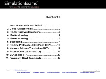
Chapter 1: IntroductionAbout the Test SetupAbout the Test SetupThe DLS-8235 uses the ETSI TS 101 270-1 specification as the basis for emulating theTP100 wireline loop. It reproduces all the characteristics (attenuation, phase, andimpedance) of the simulated loops and covers the European VDSL2 frequency spectrum.Attenuation (insertion loss) and phase are identical for both downstream and upstreamsignals.The DLS-8235 allows full-duplex signal transmission and covers the full frequency bandfrom DC to 30 MHz, which allows for testing across all variations of DSL technologies.Combined, the DLS-8235 VDSL2 Wireline Simulator and the DLS-5500EV VDSL2Noise Generation System form an integrated system with the required wireline simulationand noise files to support VDSL2 ETSI testing.Figure 1-1 illustrates an example of a typical test setup using the DLS-8235 VDSL2Wireline Simulator. This test setup provides users with a comprehensive and accurate testbed for verifying that the Device Under Test (DUT) meets the testing requirements of theVDSL2 standards. Spirent AE solution users know that this functionality translates intorobust performance, earlier product delivery, and greater market share.Figure 1-1. Example of a VDSL2 Test System SetupFor more information on compatible Spirent Communications products, see “References”on page 8.DLS-8235 Operating Manual 13
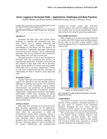
Chapter 1: IntroductionAbout the Test SetupLoopThe DLS-8235 simulates a TP100 loop as illustrated in Figure 1-2. The loop has acontinuous bandwidth of DC to 30 MHz.L1ABTP1000; 50 to 3000 meters5-meter incrementsFigure 1-2. DLS-8235 Loop SchematicThe TP100 cable model is based on the ETSI TS 101 270-1 document. See “References”on page 8.14 DLS-8235 Operating Manual
Chapter 2Getting StartedThis chapter provides basic instructions on the setup of a DLS-8235 VDSL2 WirelineSimulator.Note: Read this chapter thoroughly before powering up your DLS-8235.In this chapter. Receiving and Unpacking the Unit . . . . 16 Setup Overview . . . . 17 Front Panel Components and Connections . . . . 18 Back Panel Components and Connections . . . . 20 Chassis Setup . . . . 24DLS-8235 Operating Manual 15
Chapter 2: Getting StartedReceiving and Unpacking the UnitReceiving and Unpacking the UnitEach DLS-8235 chassis is shipped in a reinforced shipping container. Please keep thiscontainer in case you need to ship the wireline simulator to another location or for repair.You will need to ship the unit for the recommended yearly calibration.The DLS-8235 system contains the following: One DLS-8235 chassisOne power cordTwo extra fusesOne 9-to-25 pin adapter (RS-232)One RS-232C interconnection cableOne GPIB interconnection cableOne GPIB reverse-entry extenderTwo RJ-45 interconnect cables: 30 cm (1 foot) long, Spirent part number 7102040514One DLS-8235 Software CDOne Operating Manual CDOne diskette containing compensation settings specific to the shipped unitCheck that you have received all the items on the list and report any discrepancies toSpirent Communications. See Chapter 7, “Shipping the Unit,” for information.16 DLS-8235 Operating Manual
Chapter 2: Getting StartedSetup OverviewSetup OverviewThe following steps outline how to set up a DLS-8235 system. For details, see the sectionsreferred to in the steps.To set up the DLS-8235:1Install the DLS-8235 Control Software (see “Installing the Software” on page 29).2Connect the chassis to the control computer (“Control Computer Connection” onpage 21).3Set up the equipment (“Chassis Setup” on page 24).4Connect the DLS-8235 to the Digital Subscriber Line Access Multiplexer (DSLAM)and CPE equipment (“Chassis Interconnections” on page 25).5Connect power to the chassis and switch it on (“Power Connection” on page 20).6Start the DLS-8235 software (“Starting the DLS-8235 Control Software” on page29).7Select the Communication Settings tab.8Configure the appropriate GPIB or serial port settings.9Select the System Properties tab.10 Select the loop type.11 Adjust the wireline segment length.12 If using a DLS-5500EV VDSL2 Noise Generation System, select the desired impairments using the software that comes with that system.13 Begin testing.DLS-8235 Operating Manual 17
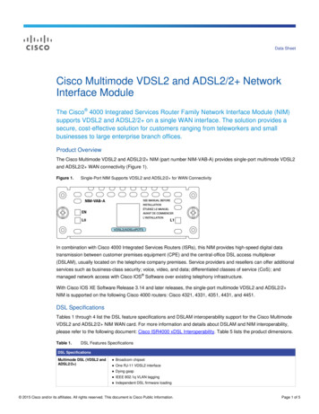
Chapter 2: Getting StartedFront Panel Components and ConnectionsFront Panel Components and ConnectionsFigure 2-1 shows the layout of the DLS-8235 front panel.123456Figure 2-1. DLS-8235 VDSL2 Wireline Simulator Front PanelThe DLS-8235 Front Panel components are:1Side A, RJ-45 connector: wireline Side A2Ext A, RJ-45 connector: not used3POWER LED: indicates the power status4REMOTE LED: indicates the remote status5Ext B, RJ-45 connector: not used6Side B, RJ-45 connector: wireline Side BREMOTE and POWER Status LEDsThe DLS-8235 chassis has two LEDs that indicate the power and remote status.The POWER LED is green when the power is turned on. It is red when the chassis fails itsself-test. It is yellow when an internal error is detected.The REMOTE LED is off after a power-up or a reset. After receiving a remote message,the REMOTE LED turns green for valid commands or red when a command generates anerror. Errors are usually caused by an invalid
and control the wireline simulator. If you decide to develop custom test software, see Chapter 5, "Remote Control," for common and device-specific command sets that can be sent to the DLS-8235 control module through the GPIB or RS-232 interfaces. If you have any questions about the DLS-8235 VDSL2 Wireline Simulator, please contact