Transcription
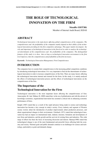
Application ReportsWireline –Highly Technological Equipment for Measurement and ControlIntervention on Oil and Gas Wellsby Sandra WassinkFloating drilling unit for offshore useThe production process of oil and gasIn the production process of oil & gas, several steps have to betaken: Exploration, production, transportation and storage.Page 34 Ex-Magazine 2011
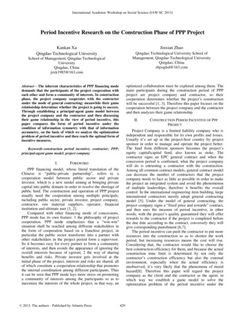
ExplorationThe first step in the complete process of producing oil and gasis exploration. The world is explored for potential petroleum reserves. In the exploration process four stages take place: collectionof geological knowledge, seismic surveying, drilling and testing.Based on geological knowledge and the seismic survey thedrilling will start. For drilling a drill tower is used. This can also bereferred to as a ›drilling mast‹ or ›derrick›. A ›drill string‹ is attachedto the drill tower with a bit. The elevated platform under the drillingtower is called a ›drill floor‹. The drill floor is the heart of the tower,which contains a rotary table that is responsible for the rotation ofthe drill string, and is where all assembly tools for the drill string arelocated.During the drilling process a fluid called mud is used to circulate into and out of the well. A Blow Out Preventer (BOP) is used toensure closing the well under certain conditions in order to preventthe mud from blowing out of the hole. A Blow Out Preventer is a largespecialized valve to seal, control and monitor oil and gas wells. Theywere developed to cope with extreme pressures and uncontrolledflow emanating from a well reservoir during drilling. The Blow OutPreventer is installed on the drill floor. To keep the mud circulating,high pressure pumps – so-called mud pumps – can be used. Theseare located near the drill floor.The mud protects the borehole from collapsing. The final collapse protection is provided by the casing; a steel pipe lowered intothe hole and firmly set by pumping cement between the casing outside and the formation. This is called a ›cased borehole‹.Of all exploration phases, drilling is the most visible one. Themaking of a hole can may take many weeks and in some cases manymonths. The cost for drilling is high, but if proper data analysis isavailable, the chance of success is also high. The first well providesvaluable geophysical information, and it would be extremely lucky, ifit also happened to be placed in the optimum position in the oil or gas containing layers.Figure 1: Oil wellChristmas treeFigure 2: Types of offshore platforms and drilling rigs. From left to right:1 2 conventional fixed platforms, 3 compliant tower, 4 5 vertically moored tension leg and mini-tension leg platform, 6 spar, 7 8 semi-submersibles,9 FPSO (floating production storage and offloading facility), 10 sub-sea completion and tie-back to host facilityEx-Magazine 2011 Page 35
WirelineFigure 3: Pipeline for oil transport from the separators nearly situatedat the wells to further processingOffshore drilling is not much different from onshore drilling.However, drilling an exploration well at sea is almost always done bymeans of a MODU, Mobile Drilling Unit. This may be a drilling ship,but could also be a semi-submersible drilling platform or a self-elevating (jack-up) platform.During the drilling process, measurements are taken in theborehole, for example to establish the electric conductivity of thesoil, the radioactivity or the acoustic properties. A test assembly isplaced near the bottom of the hole, to record the downhole pressure.Also oil and gas samples are taken to analyse composition, viscosity,specific and density. All data obtained along with the reservoir volume established by seismic and drilling, and with the gas-oil-waterinterfaces and the porosity of the rock formation allow an estimationof the quantity of oil in place and the percentage producible.DevelopmentWhen an exploration well indicates interesting quantities of oiland gas, further development starts with the drilling of additionalwells to establish the size, the productivity and the contours of thefield in more detail; the so-called ›appraisal wells‹ and ›delineationwells‹. The seismic images are extremely important when the sites ofthe extra wells are determined. From the seismic information plusthe data of ›appraisal wells‹ the total amount of producible oil or gasin the reservoir can be estimated.Drilling a production well is very similar to drilling an exploration well. However, there are some differences. An exploration wellis normaly drilled vertically, whereas production wells are oftendrilled from a single site at the surface to different areas of the formation in what is referred to as ›directional drilling‹.After drilling and casing the well, it must be ›completed‹. Wellcompletion is the process in which the well is enabled to produce oilor gas. Like in exploration wells, casings are placed in the production well. The casing pipes are secured in place with cement (CasedHole). Finally ›production tubing‹ is let down inside the casing. Afterclosing off the room between tubing and casing, the well is ready forproduction. The production tubing will carry the well fluids to thesurface. Completion includes some work at the surface, to controlPage 36 Ex-Magazine 2011the well flow. A number of valves and chokes are placed on top ofthe wellhead. The assembly of the valves, chokes and piping iscalled the Christmas tree (Figure 1).Separation of oil, gas and waterOnce the presence of oil or gas has been proven, the most difficult part of the exploration and production process would seem tobe finished. However, it is not simply a matter of feeding the mixtureof oil, gas and other fluids coming out of the well, into a tank or pipeline; it requires conditioning.The fluid flowing out of the well is not purely oil; almost alwayssome gas is dissolved in the petroleum. While oil is flowing upwardthrough the production tubing, gas is released. The oil may be contaminated with water, usually salt water, or sand. This needs to beremoved before it damages the pipeline. This is done by a productioninstallation, with one or several separators.After the oil has been separated from the gas, water and sand,the oil will be forwarded to a local production centre via short pipelines, called ›flowlines‹. The centre contains separators and otherproduction equipment, and often storage tanks.The main difference in offshore production is its location in themiddle of the sea, which requires a platform above water for placingthe wellheads, Christmas trees, separators, pumps and so on. A platform at sea is always more expensive than a small stretch of realestate on land. The most common platform types are: jacket platform, gravity structures, Tension Leg Platform (TLP) and Spar Platform, Semi-submersible (FPSS), Floating Production Storage and Offloading Ships (FPSO), (Figure 2).Transportation and storageTransportation of the oil from the well to consumers is donethrough a network of pipelines, refineries, cargo holds of tank ships,and eventually train and road (Figure 3). Transportation of crude oilfrom oil fields to refineries mainly takes place through pipelines andthe use of large ships.
MaintenanceOil and gas wells need occasional maintenance. The tubingmay need replacement or the perforations of the rock around thewell may have plugged during years of production. If the problemsare contained by maintenance, a well may flow for years withoutproblems. Here the importance of wireline service comes in.Wireline Technology in the process of oil & gas productionWireline, what is that?In the oil and gas industry, the term wireline usually refers to acabling technology used by operators of oil and gas wells to lowerequipment or measurement devices into the well for the purposes ofwell intervention and reservoir evaluation, and additionally it may also be used as a guy rope.The braided line can contain an inner core of insulated wires whichprovide power to equipment located at the end of the cable, normallyreferred to as electric line, and provides a pathway for electrical telemetry for communication between the surface and equipment atthe end of the cable.For oilfield work, the wireline resides on the surface, woundaround a large (3 to 10 feet in diameter) spool, called a winch. Foronshore applications users may use a portable spool, for example onthe back of a special truck, or one set up as a permanent part of thedrilling rig. A motor and drive train turn the spool, and raise and lower the equipment into and out of the well. For offshore application the spool can be placed in a container.Figure 4: Wireline attached to the top of a Christmas TreeFigure 5: Wireline truck with drum (inside)Ex-Magazine 2011 Page 37
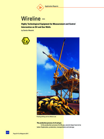
WirelineStuffing boxPower plantWinch unitPressure control equipmentLubricatorMeasuring headThe WireBlow out PreventerThe fundamental elements required to perform a wireline service are(Figure 6): Power unit Winch unit Measuring head Pressure control equipment The wire ToolsAdvantages of WirelineWireline tasks can easily be performed when a well is underpressure. This has the obvious advantage that the well does notneed to be killed. Production can continue unhindered and there isno time lost. Killing a well is costly and time consuming, and damagecan occur. Additionally, it is time consuming and costly getting a wellback into production.The WireToolsFigure 6: Wireline, cased hole servicesWireline loggingWireline logging refers to the practice within the oil and gasindustry of lowering a logging device attached to a wireline into aborehole or oil well to measure the properties of the rock and fluidsof the formation. The measurements obtained are then interpretedand used to determine the depths and zones where oil and gas canbe expected to be found.Figure 7: A winch in a container for offshore applications.Rig Power Supply 230 VRig Power Supply 380 V – 690 VRig Fibre OpticWell ControlUnitWhinch UnitPower UnitControl CabinTest UnitEthernetCANPage 38 Ex-Magazine 2011GreaseInjection UnitFigure 8:Power Supply and communicationsystem for Wireline
Figure 9 and 10: Smart Monitor with controlWireline for Kristin oilfield in NorwayThe Norwegian company Statoil is responsible for oil production at ›Kristin Field‹, located in the south-western part of the HaltenBank in the Norwegian Sea. The field was developed with 12 production wells in four subsea templates, tied back to a semi-submersibleproduction platform.The wire lining has been outsourced to several companies.Wireline units are used at this production site for wireline loggingand maintenance, in this case referred to as ›cased hole‹ services.It is most common to use the wireline unit outside the hazardous areas or in a Zone 2 environment (placed on a truck for onshoreapplications). However, for this specific application a Zone 1 unitwas required.Electromach b.v. / R. STAHLAlready in an early stage the company Electromach B.V. wereinvolved in the discussions how to create a complete zone 1 wirelineapplication. A huge advantage, compared to the competition, wasthe combination of long-term relationship, workshop, knowledge andexperience in explosion protection technology, good contacts withthe notify bodies, flexibility in development and last but not least thewide range of products, which makes a one-stop-shopping possible.Electromach received the order to supply 16 complete wirelineunits, of which every application contained 6 containers: a winchunit, a control cabin, a power unit, a well control unit, a grease injec tion unit and a test unit (Figures 7 and 8).Figure 11: Monitoring winch with camerasEx-Magazine 2011 Page 39
WirelineSmart monitor with control for Control CabinFor the visualization of the control software of the applicationa new modern explosion protected PC and a special control wasneeded in the Control Cabin. The Open-HMI of STAHL-HMI was customized to the demands of the customer. Communication was basedon CAN-Bus protocol. The hardware/software combination is calledSmart Monitor (Figures 9 and 10).Winch unitFor monitoring the winch a ›small‹ explosion protected camerawas required. After testing several possibilities, R. STAHL’s compactzoom camera (EC-710) and dome camera (EC-750) were selected.The camera images are integrated into the Smart Monitor application (Figure 11).Power unitTo provide the applications with the required power, the powerpack was equipped with a large transformer (90KVA) and a frequency converter. The converter, equipped with a cooling plate, was builtinto a flameproof enclosure (CUBEx series). The connection for thecooling fluid was made directly on the CUBEx (Figures 12 and 13).Space was a critical issue in this project, because of the limited space on the production platforms. The containers had to be builtas compact as possible. The use of the modular CUBEx flameproofenclosures contributed to a more compact installation (Figure 14).Figure 12: Frequency converter with active cooling systemin a flameproof enclosureConclusionWith the early co-operation between user, developer andmanufacturer the exceptional and difficult demands on the ›WirelineSystem‹ in regard to explosion protection and application environment have been optimally solved. The experience Electromach andR. STAHL have with similar tasks for the oil and gas industry had avery positive effect here. So the explosion-protected Wireline-unitfor use in Zone 1 that is described here can be qualified as a ›topperformance‹ of the two manufacturers. The wireline unit which wasdesigned for ›Kristin Field‹ can be categorized as ›top of the line‹.Figure 13: Connection for cooling fluid at CUBEx enclosurePage 40 Ex-Magazine 2011
Figure 14: Power pack container (in progress), compact designEx-Magazine 2011 Page 41
The fundamental elements required to perform a wireline service are (Figure 6): Power unit Winch unit Measuring head Pressure control equipment The wire Tools Advantages of Wireline. Wireline tasks can easily be performed when a well is under pressure. This has the obvious advantage that the well does not . need to be killed.