Transcription
GETTING READYINSTALLATION GUIDETOOLS AND EQUIPMENT REQUIRED FOR ASSEMBVertical FlowCAP577INSTALLATION & MAINTENANCE INSTRUCTIONS FORCAP577Vertical Flow Softwall Modular CleanroomEngineering Solutions with Value and Integrity2007068605 Wyoming Avenue N. Minneapolis, MN 55445763-425-9122 800-423-9728 Fax: 763-425-2004E-Mail: sales@cleanairproducts.comwww.cleanairproducts.com
INSTALLATION & MAINTENANCE GUIDECAP577Vertical Flow Softwall Modular CleanroomSUPPLIED HARDWARE One or more A-frame style ladders that allow workers safe access above the cleanroom ceiling.**A sheet good lift can be useful to help position the filters in the ceiling.**Review the details of the clean rooms design and become familiar with the layout andoptional items that have been included. Many of these options affect the build process.Relevant documents can be found on the following pages. **8605 Wyoming Ave. N. Minneapolis, MN 55445 763-425-9122 800-423-9728 Fax 763-425-2004210226www.cleanairproducts.com2
INSTALLATION & MAINTENANCE GUIDECAP577Vertical Flow Softwall Modular Cleanroom8605 Wyoming Ave. N. Minneapolis, MN 55445 763-425-9122 800-423-9728 Fax 763-425-2004210226www.cleanairproducts.com3
Please observe the following information related to theproduct:1) Read this guide before installing and/or operatingthe unit and retain for future reference.2) Observe warnings associated with handling,installing, using, and maintaining the CAP577.3) Follow all instructions for set-up, operation, anduse.4) Operate ONLY from the type of power sourceindicated. If you are unsure of the type of poweravailable to you, contact your dealer or powercompany.5) This unit may be equipped with a polarizedalternating current (AC) plug with one blade widerthan the other. This plug will only fit into the poweroutlet in one way for safety reasons. If the plug doesnot fit, call an electrician to replace the outlet. DO NOTREMOVE THE ROUND GROUNDING TERMINAL. THISUNIT MUST BE GROUNDED FOR SAFETY REASONSAND FOR PROPER OPERATION.6) Do not place power cords (optional) where they willbe damaged, especially near the outlet, the plug, orwhere the power cord exits the unit.7) Overloading outlets and/or extension cords canresult in fire and/or electrical shock.8) ONLY use parts supplied or authorized by themanufacturer. Substitutions may result in fire,electrical shock, or other safety hazards.Safety Warnings1) NEVER expose the assembly to moisture or rain.2) If the unit gets wet, disconnect the power at thesource and have an authorized service inspectionbefore using it again.3) Do not pull on the optional power cord to unplugthe unit, and never handle the cord with wet hands.4) Do not clean the unit with flammable chemicals.5) Do not expose to explosive or hazardous vapors ormaterials.6) Make sure the unit is well supported to preventfalling.7) Do not block airflow to the unit.8) Disconnect the power before servicing.9) Do not operate below 0 degrees Fahrenheit orabove 110 degrees Fahrenheit.10) This unit is designed to operate in a nonhazardous (non-explosive) environment with noncondensing air.11) NEVER put objects into the blower.12) Do not operate without metal blower guard.13) Review application with your safety commissionerfor proper use
INSTALLATION & MAINTENANCE GUIDECAP577Vertical Flow Softwall Modular CleanroomGETTING READY: UNPACK BEAMSLocate the area that the clean room is going to be assembled and mark out on the ground the final dimensions ofthe room with tape or suitable substitute. This is helpful in a later step to ensure the room is “true” and square.** ONLY USE IPA AS CLEANER ON PAINTED METAL SURFICES TO AVOID RESIDUES THAT MAY CAUSEISSUES WITH THE DUAL LOCK ADHESIVE **Open the beam boxes on the ground and leave the beams on the boxes. Remove and dispose of the shipping blocksand shipping hardware.8605 Wyoming Ave. N. Minneapolis, MN 55445 763-425-9122 800-423-9728 Fax 763-425-2004210226www.cleanairproducts.com8
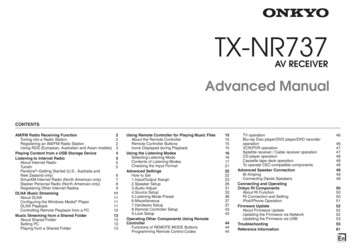
INSTALLATION & MAINTENANCE GUIDECAP577Vertical Flow Softwall Modular CleanroomFRAME PREPARATIONReference your Curtain drawing at the beginning of the manual for the beam layout. On the ground, arrange andbolt together one section of side beams and their corresponding center beam(s) as seen in the diagram below.Ensure that the 11/64” holes running along the beams are oriented UP. Keep the beams protected by keeping themon their shipping boxes. Note the installation order of the washer, lock washer and bolt in the diagram below.EXAMPLE CURTAIN DRAWINGBEAM ASSEMBLY EXAMPLEROOM NOTES:*Larger rooms with more than 4 legs will start by building one “Four Leg Section” of the frame and then addadditional beam sections to the standing structure as described in the FRAME ASSEMBLY section.8605 Wyoming Ave. N. Minneapolis, MN 55445 763-425-9122 800-423-9728 Fax 763-425-2004210226www.cleanairproducts.com9
INSTALLATION & MAINTENANCE GUIDECAP577Vertical Flow Softwall Modular CleanroomLEG PREPARATIONNote the installation order of the washer, lock washer and bolt. Attach the corner brackets (577 Corner Gusset) tothe legs by manually turning the bolt three full threads by hand. This reduces the chances of cross threading whenusing a power driver. Assemble the brackets with the open sides towards each other as seen below. Leave the boltsloose until the legs are attached to the frame.NOTES: *Rooms over 8’ in height have special Right and Left handed extended Brackets and matching legs8605 Wyoming Ave. N. Minneapolis, MN 55445 763-425-9122 800-423-9728 Fax 763-425-2004210226www.cleanairproducts.com10
INSTALLATION & MAINTENANCE GUIDECAP577Vertical Flow Softwall Modular Cleanroom*Rooms with six or more legs will require assembling legs with 3 or 4 brackets. Reference the curtain drawing at thebeginning of this manual for quantity and locations.*Rooms with casters will require the installation of the casters into the legs. The casters are shipped separately inthe hardware box. Slide the top of the caster insert into the bottom of the leg. If necessary, carefully drive theinsert in with a mallet and dowel.8605 Wyoming Ave. N. Minneapolis, MN 55445 763-425-9122 800-423-9728 Fax 763-425-2004210226www.cleanairproducts.com11
INSTALLATION & MAINTENANCE GUIDECAP577Vertical Flow Softwall Modular CleanroomFRAME ASSEMBLYUsing a cardboard box under the beams, position the Lift so that the fork extensions span under a center beam(s).Clamp the Frame to the fork extension to aid stability. Position a worker on a ladder at a corner to help carefully liftthe structure to the room height. Position a leg in the corner and bolt the leg bracket and corner strut to the sidebeam as shown. Leave the lift in place and repeat this process at each corner.8605 Wyoming Ave. N. Minneapolis, MN 55445 763-425-9122 800-423-9728 Fax 763-425-2004210226www.cleanairproducts.com12
INSTALLATION & MAINTENANCE GUIDECAP577Vertical Flow Softwall Modular CleanroomWith all four legs attached use one person on each end to lift the additional side beams into place. Bolt them to theleg brackets while securing the second side of the corner struts. Check the frames dimensions and the spacing ofthe legs at the floor to ensure the room is square while tightening all bolts. It is now safe to remove the lift. Use theleg levelers to plumb the room.ROOMS W/ MULTIPLE SECTIONS:Larger rooms with multiple sections are built by addingadditional sections to the first by following the sameprocedure.8605 Wyoming Ave. N. Minneapolis, MN 55445 763-425-9122 800-423-9728 Fax 763-425-2004210226www.cleanairproducts.com13
INSTALLATION & MAINTENANCE GUIDECAP577Vertical Flow Softwall Modular CleanroomFRAME ASSEMBLYLocate all unused 3/8” holes in the frame and legs and insertthe 3/8” white nylon slotted screws (056586). Gasket thetops of the beams with the 50’ roll(s) of 1/4” x 1/2” foamgasket (012231). Apply one strip around the inside perimeterof the room and two strips down the center beams as shown.If prefabricated wiring was purchased determine thelocation and orientation of the optional prefabricatedwiring panel. Inspect the approval drawings anddetermine the orientation of the 4’ sides of the ceilingpanels. This is the side that will have T-bars. Theelectrical mounting angle will be orientated in thesame direction as the T-Bars and be installed in placeof one. Mount the angle and then position and mountthe electrical box with (3) 10x1/2 Self Drillingscrews(000960). Do not add clips to the conduit ormount the light switch until after the curtains areinstalled.8605 Wyoming Ave. N. Minneapolis, MN 55445 763-425-9122 800-423-9728 Fax 763-425-2004210226www.cleanairproducts.com14
INSTALLATION & MAINTENANCE GUIDECAP577Vertical Flow Softwall Modular CleanroomCEILING ASSEMBLY**CAUTION: While working with the filter units do not touch the filter screen. Filterdamage may result. **Choose the layout of the filter units in the ceiling grid or refer to the reference drawings. Install them one by onestarting nearest to the wiring location so that they can be wired as they are installed. Daisy chain the filterstogether using the prefabricated connecters if ordered. Do not connect more than (6) to a circuit.It is easiest to remove the filter with a helper. Hold the box steady and grasp the prefilter frame. Carefully pull thefilter out and rest it perpendicularly on the box to prevent damage to the filter media.To install a filter unit place cardboard on the lift supports to protect the filter. Carefully rest a filter unit on thecardboard and lift the filter to the height of the beam grid. Carefully, avoiding contact with the filter screen, tilt thefilter through the frame to rest on the tops of the beams between two holes (11/64”) .8605 Wyoming Ave. N. Minneapolis, MN 55445 763-425-9122 800-423-9728 Fax 763-425-2004210226www.cleanairproducts.com15
INSTALLATION & MAINTENANCE GUIDECAP577Vertical Flow Softwall Modular CleanroomSlide a T-bar (006266) under one edge of the filter housing and attach it to the frame with a Washer (001129),Ceiling clip (004624) and 10-32 screw (000923) in the predrilled hole. Repeat the process of adding a T-bar to theother side of the filter. Continue to repeat this process to install the rest of the Filter units and Lights. When wiringis complete install the remaining T-Bars and ceiling clips to complete the grid before lifting the Gypsum ceilingpanels into place.**MAXIMUM 6 Filter Units per 20A Circuit**16 Lights per connector/ MAXIMUM 32 lights per 20A Circuit8605 Wyoming Ave. N. Minneapolis, MN 55445 763-425-9122 800-423-9728 Fax 763-425-2004210226www.cleanairproducts.com16
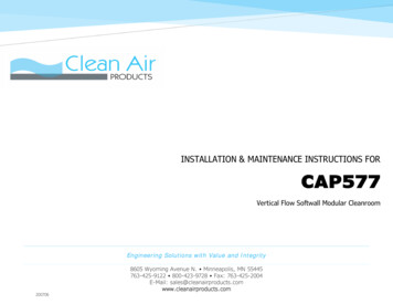
INSTALLATION & MAINTENANCE GUIDECAP577Vertical Flow Softwall Modular CleanroomCURTAIN INSTALLATIONAttach the 1 inch wide “fine” Dual Lock to the outside TOP EDGE of the rooms frame. Refer to the included CurtainDrawing for suggested positioning and orientation of the cleanroom curtains.If strip doors were ordered locate their positions and install them onto the Dual Lock. Use (3) #8 self-drilling Panhead screws (000919) to secure the door frames to the Beams.Next place your Filler Curtain(s). Filler curtains have Dual Lock on the full width of both sides of the curtain to allowfor the end curtain to overlap as needed. The filler curtain(s) will be located next to a strip door or at a room corneras seen on yourrooms curtaindrawing. Be sure toattach the coarseside of the DualLock inwards to thealready hung “Fine”style Dual Lock.Start hangingcurtains on theother side of thestrip door and workaround the roomuntil the last curtainoverlaps the FillerCurtain. Eachcurtain will overlapthe last by 6” byattaching to the“Fine” Dual Lockmounted to theoutside of the last curtain.8605 Wyoming Ave. N. Minneapolis, MN 55445 763-425-9122 800-423-9728 Fax 763-425-2004210226www.cleanairproducts.com17
INSTALLATION & MAINTENANCE GUIDECAP577Vertical Flow Softwall Modular CleanroomFINISHING THE ROOMAfter all curtains have been hung mount the light switch with the included bracket and complete the installation ofthe electrical box. Secure the conduit with the two supplied ¾” clamps (029622) and #10 self drilling screws(000960).Anchor the room to the floor with the included Leg Anchors (006997) and ¼” x 1-1/4” masonry anchors (001626).Use (4) #8 -1/2 self Drilling screws (000213) to attach the Leg Anchors to the Legs.8605 Wyoming Ave. N. Minneapolis, MN 55445 763-425-9122 800-423-9728 Fax 763-425-2004210226www.cleanairproducts.com18
INSTALLATION & MAINTENANCE GUIDECAP577Vertical Flow Softwall Modular CleanroomMaintenance of the CAP 577PREFILTERSIt is recommended that the prefilters be visually checked on a regular basis. If the filter appears dirty, it is time toreplace it. Typically, one would change the prefilters once a month. However, some environments may requiredifferent replacement intervals.HEPA/ULPA FiltersIt is recommended that clean rooms be certified by a third party on an annual basis. Certification will verify theexpected class of the room. As the HEPA/ULPAs are new, the rooms have a certain number of air changes per hourbased upon the class of the room. As the HEPA/ULPAs get dirty, the air changes per hour goes down. If the prefabwiring kit was purchased, the speed control should then be turned up so the velocity out of the filters reaches 90feet/min. average face velocity. This will provide the proper air changes per hour. When the velocity falls to 70feet/min. and the speed control is at its highest setting, the filters need to be changed. If this situation occurs, itdoes not mean that the room is not functioning, it just means the conditions are not ideal and the filters need to bereplaced.If you do not have access to a velocity meter or cannot get certification, a general rule of thumb is that the filtersshould last 3 to 5 years and can last as long as 10 years depending on the cleanliness of the environment.MOTORSThe motors do not need maintenance. They are permanently lubricated.GENERAL CAREPeriodically check cleanroom components to be sure they are in good working order.Clean the interior of the cleanroom and floors on a regular basis.Check the filter velocity on a regular basis.Annually check filters for leaks.8605 Wyoming Ave. N. Minneapolis, MN 55445 763-425-9122 800-423-9728 Fax 763-425-2004210226www.cleanairproducts.com19
INSTALLATION & MAINTENANCE GUIDECAP577Vertical Flow Softwall Modular CleanroomWarranty InformationClean Air Products Corporation warrants that it will repair FOB its factory or furnish without charge FOB its factory a similar partto replace any material in its equipment within one year after the date of sale if proved to the satisfaction of the company tohave been defective at the time it was sold provided that all parts claimed defective shall be returned, properly identified to thecompany at its factory, freight charges prepaid. Factory installed equipment of accessories is warranted only to the extentguaranteed by the original equipment manufacturer, and this warranty shall not apply to any portion of the equipment modifiedby the user. Claims under this warranty should be directed to Clean Air Products, 8605 Wyoming Avenue North, Brooklyn Park,MN 55445, setting forth in detail the nature of the defect, the date of the initial installation, and the serial number and modelnumber of the equipment.HEPA filters are warranted to have their given efficiency at the time of shippingParts shipped to replace warranty items shall be invoiced out with 60 day terms. Credit shall be issued when defective parts arereturned to Clean Air Products’ factory. (Contaminated materials shall be credited after receipt of proper disposal is sent toClean Air Products.)When special shipping containers are used to ship out new product, defective parts are to be returned in the same container.This shall be so stated on the Bill of Lading sent with the replacement parts.Contaminated Parts and EquipmentClean Air Products must be notified if defective parts, or other materials supplied to the purchaser are contaminated withhazardous chemicals or carcinogenic materials that are considered hazardous or carcinogenic by the EPA or other regulatoryagencies. These parts are not to be shipped back to Clean Air Products’ factory. The purchaser shall be responsible for properdisposal and all costs associated with the disposal and/or storage of the defective contaminated equipment. Prior to theirdisposal, Clean Air Products may require inspection of said defective materials.The user and purchaser shall each be responsible and be back charged for cleanup and disposal of all contaminated materialsshipped back to Clean Air Products’ factory.8605 Wyoming Ave. N. Minneapolis, MN 55445 763-425-9122 800-423-9728 Fax 763-425-2004210226www.cleanairproducts.com20
8605 Wyoming Avenue N. Minneapolis, MN 55445 763-425-9122 800-423-9728 Fax: 763-425-2004 . Reference your Curtain drawing at the beginning of the manual for the beam layout. . The filler curtain(s) will be located next to a strip door or at a room corner as seen on your rooms