Transcription
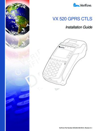
VX 520 GPRS CTLSInstallation GuideELNAIOTFNIERDEIV NFFOCMETALPTEREVVeriFone Part Number DOC252-063-EN-A, Revision A.1
VX 520 GPRS CTLS Installation Guide 2012 VeriFone, Inc.All rights reserved. No part of the contents of this document may be reproduced or transmitted in any form without the writtenpermission of VeriFone, Inc.The information contained in this document is subject to change without notice. Although VeriFone has attempted to ensure theaccuracy of the contents of this document, this document may include errors or omissions. The examples and sample programs arefor illustration only and may not be suited for your purpose. You should verify the applicability of any example or sample programbefore placing the software into productive use. This document, including without limitation the examples and software programs, issupplied “As-Is.”VeriFone, the VeriFone logo, VeriCentre, Verix, and ZonTalk are registered trademarks of VeriFone. Other brand names ortrademarks associated with VeriFone’s products and services are trademarks of VeriFone, Inc.All other brand names and trademarks appearing in this manual are the property of their respective holders.Comments? Please e-mail all comments on this document to your local VeriFone Support Team.VeriFone, Inc.2099 Gateway Place, Suite 600San Jose, CA, 95110 USAwww.verifone.comVeriFone Part Number DOC252-063-EN-A, Revision A.1
CONTENTSP R EF AC E . . . . . . . . . . . . . . . . . . . . . . . . . . . . . . . . . . . . . . . 5Audience. . . . . . . . . . . . . . . . . . . . . . . . . . . . . . . . . . . . . . . . . . . . . . . . . . . . . . . .Organization . . . . . . . . . . . . . . . . . . . . . . . . . . . . . . . . . . . . . . . . . . . . . . . . . . . . .Related Documentation . . . . . . . . . . . . . . . . . . . . . . . . . . . . . . . . . . . . . . . . . . . .Conventions and Acronyms . . . . . . . . . . . . . . . . . . . . . . . . . . . . . . . . . . . . . . . . .Document Conventions. . . . . . . . . . . . . . . . . . . . . . . . . . . . . . . . . . . . . . . . . .Acronym Definitions . . . . . . . . . . . . . . . . . . . . . . . . . . . . . . . . . . . . . . . . . . . .ELNAIOTFNIERDEIV NFFO555666C HA P TE R 1Terminal Overview Features and Benefits . . . . . . . . . . . . . . . . . . . . . . . . . . . . . . . . . . . . . . . . . . . . 10Connectivity . . . . . . . . . . . . . . . . . . . . . . . . . . . . . . . . . . . . . . . . . . . . . . . . .Performance . . . . . . . . . . . . . . . . . . . . . . . . . . . . . . . . . . . . . . . . . . . . . . . . .Security . . . . . . . . . . . . . . . . . . . . . . . . . . . . . . . . . . . . . . . . . . . . . . . . . . . . .Form Factor . . . . . . . . . . . . . . . . . . . . . . . . . . . . . . . . . . . . . . . . . . . . . . . . .Exceptional Ease of Use. . . . . . . . . . . . . . . . . . . . . . . . . . . . . . . . . . . . . . . .Countertop Performance in a Hand-Over Design . . . . . . . . . . . . . . . . . . . . .True Multi-Application Capability . . . . . . . . . . . . . . . . . . . . . . . . . . . . . . . . .10101010101111C HA P TE R 2Terminal Setup Selecting Terminal Location . . . . . . . . . . . . . . . . . . . . . . . . . . . . . . . . . . . . . . . . 13CEase of Use . . . . . . . . . . . . . . . . . . . . . . . . . . . . . . . . . . . . . . . . . . . . . . . . .Environmental Factors . . . . . . . . . . . . . . . . . . . . . . . . . . . . . . . . . . . . . . . . .Electrical Considerations . . . . . . . . . . . . . . . . . . . . . . . . . . . . . . . . . . . . . . .Unpacking the Shipping Carton . . . . . . . . . . . . . . . . . . . . . . . . . . . . . . . . . . . . .Examining Terminal Features. . . . . . . . . . . . . . . . . . . . . . . . . . . . . . . . . . . . . . .Front Panel . . . . . . . . . . . . . . . . . . . . . . . . . . . . . . . . . . . . . . . . . . . . . . . . . .Connection Ports . . . . . . . . . . . . . . . . . . . . . . . . . . . . . . . . . . . . . . . . . . . . .Establishing Telephone Line Connections . . . . . . . . . . . . . . . . . . . . . . . . . . . . .Installing a Paper Roll in the Printer . . . . . . . . . . . . . . . . . . . . . . . . . . . . . . . . . .Installing/Replacing MSAM Cards . . . . . . . . . . . . . . . . . . . . . . . . . . . . . . . . . . .Connecting Optional Devices . . . . . . . . . . . . . . . . . . . . . . . . . . . . . . . . . . . . . . .Optional Device Connections . . . . . . . . . . . . . . . . . . . . . . . . . . . . . . . . . . . .External Printers Supported . . . . . . . . . . . . . . . . . . . . . . . . . . . . . . . . . . . . .Connecting the Terminal Power Pack . . . . . . . . . . . . . . . . . . . . . . . . . . . . . . . .Privacy Shield (Optional) . . . . . . . . . . . . . . . . . . . . . . . . . . . . . . . . . . . . . . . . . .Using the CTLS Reader . . . . . . . . . . . . . . . . . . . . . . . . . . . . . . . . . . . . . . . . . . .Using the Smart Card Reader . . . . . . . . . . . . . . . . . . . . . . . . . . . . . . . . . . . . . .Using the Magnetic Card Reader . . . . . . . . . . . . . . . . . . . . . . . . . . . . . . . . . . . .131314141515161919212323252627282930Power . . . . . . . . . . . . . . . . . . . . . . . . . . . . . . . . . . . . . . . . . . . . . . . . . . . . . .DC Power Pack. . . . . . . . . . . . . . . . . . . . . . . . . . . . . . . . . . . . . . . . . . . . . . .Temperature . . . . . . . . . . . . . . . . . . . . . . . . . . . . . . . . . . . . . . . . . . . . . . . . .External Dimensions . . . . . . . . . . . . . . . . . . . . . . . . . . . . . . . . . . . . . . . . . . .31313131METC HA P TE R 3SpecificationsALPTEREVVX 520 GPRS CTLS INSTALLATION GUIDE3
C ONTENTSC H AP T ER 4Maintenance Clean the Terminal . . . . . . . . . . . . . . . . . . . . . . . . . . . . . . . . . . . . . . . . . . . . . . . 33Terminal Contacts . . . . . . . . . . . . . . . . . . . . . . . . . . . . . . . . . . . . . . . . . . . . . . . 33Smart Card Reader . . . . . . . . . . . . . . . . . . . . . . . . . . . . . . . . . . . . . . . . . . . . . . 33C H AP T ER 5Troubleshooting Blank Display . . . . . . . . . . . . . . . . . . . . . . . . . . . . . . . . . . . . . . . . . . . . . . . . . . . 35Guidelines Terminal Does Not Dial Out . . . . . . . . . . . . . . . . . . . . . . . . . . . . . . . . . . . . . . . . 36Printer Paper Jam. . . . . . . . . . . . . . . . . . . . . . . . . . . . . . . . . . . . . . . . . . . . . . . .Keypad Does Not Respond . . . . . . . . . . . . . . . . . . . . . . . . . . . . . . . . . . . . . . . .Peripheral Device Does Not Work . . . . . . . . . . . . . . . . . . . . . . . . . . . . . . . . . . .Transactions Fail To Process . . . . . . . . . . . . . . . . . . . . . . . . . . . . . . . . . . . . . . .Printer Does Not Print. . . . . . . . . . . . . . . . . . . . . . . . . . . . . . . . . . . . . . . . . . . . .Terminal Display Does not Show Correct or Readable Information . . . . . . . . . .Terminal Does Not Start . . . . . . . . . . . . . . . . . . . . . . . . . . . . . . . . . . . . . . . . . . .ELNAIOTFNIERDEIV NFFO36363637383838C H AP T ER 6VeriFone Service Return a Terminal for Service. . . . . . . . . . . . . . . . . . . . . . . . . . . . . . . . . . . . . . . 39and Support Accessories and Documentation . . . . . . . . . . . . . . . . . . . . . . . . . . . . . . . . . . . . 40Printer Paper. . . . . . . . . . . . . . . . . . . . . . . . . . . . . . . . . . . . . . . . . . . . . . . . .Supplementary Hardware . . . . . . . . . . . . . . . . . . . . . . . . . . . . . . . . . . . . . . .VeriFone Cleaning Kit . . . . . . . . . . . . . . . . . . . . . . . . . . . . . . . . . . . . . . . . . .Telephone Line Cord . . . . . . . . . . . . . . . . . . . . . . . . . . . . . . . . . . . . . . . . . .Documentation . . . . . . . . . . . . . . . . . . . . . . . . . . . . . . . . . . . . . . . . . . . . . . .4040404041I N DE X . . . . . . . . . . . . . . . . . . . . . . . . . . . . . . . . . . . . . . . . . 43CMET4VX 520 GPRS CTLS INSTALLATION GUIDEALPTEREV
PREFACEThis guide is your primary source of information for setting up and installingthe VX 520 GPRS CTLS terminal.AudienceOrganizationThis guide is useful for anyone installing and configuring a VX 520 GPRS CTLSterminal. This manual also provides a basic description of the terminal features.This guide is organized as follows:Chapter 1, Terminal Overview. Provides an overview of the VX 520 GPRS CTLSterminal.ELNAIOTFNIERDEIV NFFOChapter 2, Terminal Setup. Explains how to set up and install the VX 520 GPRSCTLS terminal. It tells you how to select a location, establish power and telephoneline connections, and how to configure optional peripheral devices.Chapter 3, Specifications. Discusses power requirements and dimensions of theVX 520 GPRS CTLS terminal.Chapter 4, Maintenance. Explains how to maintain your VX 520 GPRS CTLSterminal.CRelatedDocumentationChapter 5, Troubleshooting Guidelines. Provides troubleshooting guidelines,should you encounter a problem in terminal installation and configuration.EVChapter 6, VeriFone Service and Support. Provides information on contactingyour local VeriFone representative or service provider, and information on how toorder accessories or documentation from VeriFone.ALPTERTo learn more about the VX 520 GPRS CTLS terminal, refer to the following set ofdocuments:METVX 520 GPRS CTLS Certifications and RegulationsVPN DOC252-061-ENVX 520 GPRS CTLS Quick Installation GuideVPN DOC252-062-ENVX 520 GPRS CTLS Reference ManualVPN DOC252-064-ENVX 520 Installation GuideVPN DOC252-003-ENVX 520 Reference ManualVPN DOC252-004-ENVX 520 GPRS Certifications and RegulationsVPN DOC252-021-ENVX 520 CTLS Certifications and RegulationsVPN DOC252-031-ENVX 520 CTLS Quick Installation GuideVPN DOC252-032-ENVX 520 CTLS Installation GuideVPN DOC252-033-ENVX 520 GPRS CTLS INSTALLATION GUIDE5
P REFACEConventions and AcronymsConventions andAcronymsThis section describes the conventions and acronyms used in this guide.Document Various conventions are used to help you quickly identify special formatting.Conventions Table 1 describes these conventions and provides examples of their use.Table 1Document ConventionsConventionBlueText in blue indicates termsthat are cross referenced.See Conventions and Acronyms.ItalicsItalic typeface indicatesbook titles or emphasis.You must install a roll of thermalsensitive paper in the printer.ELNAIOTFNIERDEIV NFFOCourierNOTECAUTIONCWARNINGTEThe courier type face isused while specifyingonscreen text, such as textthat you would enter at acommand prompt, or toprovide an URL.http://www.verifone.comThe pencil icon is used tohighlight importantinformation.RS-232-type devices do not work withthe PIN pad port.The caution symbolindicates possible hardwareor software failure, or lossof data.The terminal is not waterproof or dustproof, and is intended for indoor useonly.VEThe lighting symbol is usedDue to risk of shock do not use theRas a warning when bodilyterminal near water.Einjury might occur.TALPMAcronym Definitions Various acronyms are used in place of the full definition. Table 2 presentsacronyms and their definitions.Table 26Acronym DefinitionsAcronymDefinitionsACAlternating CurrentATMAutomated Teller MachineCPUCentral Processing UnitCRCheck ReaderCTLSContactlessDCDirect CurrentEMVEuropay MasterCard and VISAGPRSGeneral Packet Radio ServiceITPInternal Thermal PrinterVX 520 GPRS CTLS INSTALLATION GUIDE
P REFACEConventions and AcronymsTable 2Acronym Definitions (continued)AcronymDefinitionsLCDLiquid Crystal DisplayLEDLight Emitting DiodeMRAMerchandise Return AuthorizationMSAMMicromodule-Size Security Access ModulePCIPayment Card IndustryPEDPIN-Entry DevicesPINPersonal Identification NumberRAMRandom Access MemoryRJ-11Registered Jack 11ELNAIOTFNIERDEIV NFFORJ-45Registered Jack 45RS-232Recommended Standard 232SAMSecurity Access ModuleSIMSubscriber Identity ModuleVPNVeriFone Part NumberCMETALPTEREVVX 520 GPRS CTLS INSTALLATION GUIDE7
P REFACEConventions and AcronymsELNAIOTFNIERDEIV NFFOCMET8VX 520 GPRS CTLS INSTALLATION GUIDEALPTEREV
CHAPTER 1Terminal OverviewThis chapter provides a brief description of the VX 520 GPRS CTLS terminal: The VX 520 GPRS CTLS is a high performance countertop terminal withenhanced communication options. The VX 520 GPRS CTLS offers several communication options, enhanceddisplay, increased processing power, expanded memory, and two USBperipheral ports.ELNAIOTFNIERDEIV NFFOThe VX 520 GPRS CTLS terminal uses a robust, sleek, and highly functionaldesign.NOTEVeriFone ships variants of the VX 520 terminals for different markets. Yourterminal may have a different configuration from the features described in thissection.CMETFigure 1ALPTEREVVX 520 GPRS CTLS TerminalVX 520 GPRS CTLS INSTALLATION GUIDE9
TERMINAL O VERVIEWFeatures and BenefitsFeatures andBenefitsVX 520 GPRS CTLS terminals provide the right combination of features andfunctions. This includes a contactless (CTLS) reader, triple-track magnetic-stripecard reader, landed smart card reader, integrated PIN pad, and a quiet internalthermal printer (ITP).Connectivity Host USB port Client USB port Telco port RS-232 port Ethernet PortNOTEELNAIOTFNIERDEIV NFFOThe connectivity ports are easily accessible from the underside of the terminal.NOTEVeriFone ships variants of the VX 520 terminals for different markets. Yourterminal may have a different configuration from the features described in thissection.Performance C400 MHz Processor (CPU) Increased memory (128 MB Flash, 32 MB RAM) 128/64 white backlit LCD Fastest encryption/decryption appliance on the market Backlit keypadSecurity Form Factor REVIncreased Security (PCI 1.3 toEPCI 2.0)ATSDA DDA encryptionLreadyPLeading ECCMPerformance BenchmarkETThe VX 520 GPRS CTLS is ergonomically designed to fit both the traditionalcountertop and hand-over models.Exceptional Ease of Use10The contactless functionality offers a convenient payment option forconsumers. The bold design is sleek, stylish, and lightweight for conveniently handing theterminal to the consumer for PIN entry or other input. An intuitive ATM-style interface, a large 8-line by 21-character backlit displaywith backlit keypad, and extra-size menu prompts, simplify training and reducehelp desk calls. The integrated thermal printer simplifies paper loading and reduces paperjams.VX 520 GPRS CTLS INSTALLATION GUIDE
TERMINAL O VERVIEWFeatures and Benefits Countertop Performance in aHand-Over Design True Multi- ApplicationCapabilityThe triple-track, high-coercivity card reader handles most magnetic stripecards.The 32-bit processing and multi-tasking capabilities ensures fast processing ofpayment, payment-related, and value-added applications.Exceptional display and printer graphics-handling capabilities that quicklyrender logos, graphical fonts, and character-based languages.The VX 520 GPRS CTLS series of terminals ensures uncompromisingreliability from VeriFone, the worldwide leader in e-payment.The VX 520 GPRS CTLS terminal offers 32 MB of random access memory,and 128 MB dynamic memory allocation of the operating system, whichsupports multiple applications on a single terminal.ELNAIOTFNIERDEIV NFFO The primary smart card reader and the MSAMs safeguard sensitive financialdata and support multiple smart card schemes. VX 520 GPRS CTLS terminals and SoftPay EMV software are certified forEMV Level 1 and Level 2 Type approval for smart card solutions. The Verix Vor Vx EMV Library provides development of other EMV-compliantapplications. The VeriShield security architecture meets published specifications for PCIPED and provides sophisticated file authentication to prevent execution ofunauthorized software on VX 520 GPRS CTLS terminalsCMETALPTEREVVX 520 GPRS CTLS INSTALLATION GUIDE11
TERMINAL O VERVIEWFeatures and BenefitsELNAIOTFNIERDEIV NFFOCMET12VX 520 GPRS CTLS INSTALLATION GUIDEALPTEREV
CHAPTER 2Terminal SetupThis chapter describes the terminal setup procedure. You will learn about: Selecting Terminal Location Unpacking the Shipping Carton Examining Terminal Features Establishing Telephone Line Connections Installing a Paper Roll in the Printer Installing/Replacing MSAM Cards Connecting Optional Devices Connecting the Terminal Power Pack Privacy Shield (Optional) Using the CTLS Reader Using the Smart Card Reader Using the Magnetic Card ReaderELNAIOTFNIERDEIV NFFOCSelectingTerminalLocationEVUse the following guidelines when selecting a location for your VX 520 GPRSCTLS terminal.Ease of Use Environmental Factors ALPTERMESelect a flatTsupport surface, such as a countertop or table.Select a location convenient for both merchant and cardholder.Select a location near a power outlet and a telephone/modem line connection.For safety, do not string the power cord in a walkway or place it across awalkway on the floor.Do not use the terminal where there is high heat, dust, humidity, moisture, orcaustic chemicals or oils.Keep the terminal away from direct sunlight and anything that radiates heat,such as a stove or motor.VX 520 GPRS CTLS INSTALLATION GUIDE13
TERMINAL S ETUPUnpacking the Shipping Carton CAUTIONDo not use the terminal outdoors.The terminal is not waterproof or dustproof, and is intended for indoor use only.Any damage to the unit from exposure to rain or dust may void any warranty.Electrical Considerations Avoid using this product during electrical storms.Do not place a CTLS device within 10cm from metallic objects to avoidinterference to the CTLS field.Avoid locations near electrical appliances or other devices that causeexcessive voltage fluctuations or emit electrical noise (for example, airconditioners, electric motors, neon signs, high-frequency or magnetic securitydevices, or computer equipment).ELNAIOTFNIERDEIV NFFO Unpacking theShipping CartonOpen the shipping carton and carefully inspect its contents for possible tamperingor shipping damage. The VX 520 GPRS CTLS terminal is a secure product andany tampering may cause the device to cease to function properly.To unpack the 1shipping cartonCCAUTIONDo not use the terminal near water or in moist conditions.Remove and inspect the following items: Terminal Power pack Telephone line cord Power cordREV2 Remove all plastic wrapping from the terminal and other components.E3 Remove the clear protectivefilm from the LCD screen.TALDo not use a terminalPthat has been damaged or tampered with. The VX 520MGPRS CTLS terminalcomes equipped with tamper-evident labels. If a label orEcomponentTappears damaged, please notify the shipping company and yourVeriFone representative or service provider immediately.4 Save the shipping carton and packing material for future repacking or movingthe terminal.14VX 520 GPRS CTLS INSTALLATION GUIDE
TERMINAL S ETUPExamining Terminal FeaturesExaminingTerminalFeaturesBefore you continue the installation process, notice the features of the VX 520GPRS CTLS terminal (see Figure 2).INTERNAL THERMALPRINTERMAGNETIC CARDREADERPRINTER DOORLATCHSERRATEDMETAL STRIPCTLS LEDINDICATORSELNAIOTFNIERDEIV NFFOTERMINAL DISPLAYAND CTLS TAP AREAATM-STYLEFUNCTIONKEYSALPHA KEYCTELEPHONESTYLE KEYPADCANCEL KEYREVENTER KEYBACKSPACE/CLEAR KEYSMART CARD READERETVeriFone ships variants of the VX 520 GPRS CTLS terminals for differentFigure 2NOTEMPLATEPROGRAMMABLEFUNCTION KEYSVX 520 GPRS CTLS Terminal Features (Front Panel)markets. Your terminal may have a different configuration from the featuresdescribed in this section.Front Panel The front panel includes the following features: A terminal display, backlit LCD screen. The screen also acts as the CTLStapping area for contactless transactions. Four LED indicators above the terminal display for CTLS transactions. Five types of keys:a A backlit 12-key, telephone-style keypad.b Four ATM-style function keys, labeled F1 to F4, to the right of the LCDscreen.VX 520 GPRS CTLS INSTALLATION GUIDE15
TERMINAL S ETUPExamining Terminal Featuresc Four unlabeled, programmable function keys above the keypad.d Three color-coded function keys below thekeypad (icons at right; from left to right: CANCEL,BACKSPACE/CLEAR, ENTER).e An ALPHA key centered at the top of the keypad. A magnetic card reader, built into the right side. The icon at rightshows the proper swipe direction, with the stripe down and facinginward, toward the keypad. The VeriFone logo blue indicator LED indicates power is ON. An internal thermal printer.ELNAIOTFNIERDEIV NFFONOTEC A smart card reader, built into the front of the terminal. Theicon shown at right indicates proper card position andinsertion direction. Three SAM (security access module) compartments, built into the side ofthe terminal. The VX 520 GPRS CTLS terminal contains MSAM cardholdersto support multiple stored-value card programs or other merchant cardrequirements.VeriFone ships variants of the VX 520 GPRS CTLS terminal for different markets.Your terminal may have a different configuration. However, the basic processesdescribed in this guide remain the same, regardless of terminal configuration.Connection Ports Turn the terminal upside down and remove the rear cover to view the connectionEVports. Notice that the ports are recessed. Different ports provide connections to acommunications line, optional peripheral devices, and the power supply.REFigure 3 shows how to open therear cover of the VX 520 GPRS CTLS terminals.TALPMTE 23Figure 316VX 520 GPRS CTLS INSTALLATION GUIDEOpening the VX 520 GPRS CTLS Rear Cover
TERMINAL S ETUPExamining Terminal FeaturesFigure 4 to Figure 5 show the connection ports for the VX 520 GPRS CTLSterminal.POWER PORTRS-232 SERIAL PORT23 TELCO PORTELNAIOTFNIERDEIV NFFOFigure 4VX 520 GPRS CTLS Power and Connection PortsCHOST USB PORTR%4(TEETHERNET PORTEVMETFigure 5WARNINGALP3 CLIENT USB PORTAdditional VX 520 GPRS CTLS Connection PortsDo not connect the terminal to the power supply until all the peripherals areattached.To use the The connection ports offer multiple connectivity for the VX 520 GPRS CTLSconnection ports terminal. Please refer to the following list of peripheral devices for the connectivityoptions.VX 520 GPRS CTLS INSTALLATION GUIDE17
TERMINAL S ETUPExamining Terminal FeaturesHost USB Port PP1000 USB Vx810 USB VX 820 USB Barcode reader Biometric reader USB flash disk USB keyboardsEthernet PortELNAIOTFNIERDEIV NFFO Ethernet cable to router, hub or switchClient USB Port PC ECR/Cash registerRJ-11 Port Telephone lineRS-232 PortC PP1000 Vx810 VX 820 PC download cable Computer ECR Check reader CTLS reader Biometric reader Barcode reader KeyboardMETALPTEREVFor information on how to attach peripheral devices, see Connecting OptionalDevices.18VX 520 GPRS CTLS INSTALLATION GUIDE
TERMINAL S ETUPEstablishing Telephone Line ConnectionsEstablishingTelephone LineConnectionsConnect the telephone cord to the communication port on the terminal, then routeit directly to a telephone wall jack (see Figure 6). This is a direct connection andthe line is dedicated to the terminal.RJ-1123 ELNAIOTFNIERDEIV NFFOFigure 6WARNINGCInstalling aPaper Roll in thePrinterCAUTIONVX 520 GPRS CTLS Direct Telephone ConnectionTo reduce the risk of fire, use only No. 26AWG or larger UL Listed or CSACertified Telecommunication Line Cord.Before you can process transactions that require a receipt or record, you mustinstall paper in the printer.VEThe VX 520 GPRS CTLS uses a roll of 40Rmm-diameter, single-ply, thermalsensitive paper.ETAappearsA pink out-of-paper indicatorLlineon the edge of the paper before the endPof the roll. After this line appears,there is enough paper remaining on the roll toMconclude at least Eone transaction.TPoor-quality paper can jam the printer and create excessive paper dust. To orderhigh-quality VeriFone paper, refer to Accessories and Documentation.Store thermal paper in a dry, dark area. Handle thermal paper carefully: impact,friction, temperature, humidity, and oils affect the color and storagecharacteristics of the paper.Never load a roll of paper with folds, wrinkles, tears, or holes at the edges.VX 520 GPRS CTLS INSTALLATION GUIDE19
TERMINAL S ETUPInstalling a Paper Roll in the PrinterTo install a paper roll 1Hook your finger under the latch and lift up to swing the paper roll cover open(see Figure 7).ELNAIOTFNIERDEIV NFFOFigure 7Opening the Printer Cover2 Remove any partial roll of paper in the printer tray by lifting it up.3 Loosen the glued leading edge of the new paper roll or remove the protectivestrip. Unwind the paper roll past any glue residue.4 Hold the roll so the paper feeds from the bottom of the roll.5 Drop the paper roll into the printer tray.CMETFigure 8ALPTERLoading Paper Roll6 Pull paper up past the glue residue.20VX 520 GPRS CTLS INSTALLATION GUIDEEV
TERMINAL S ETUPInstalling/Replacing MSAM Cards7 Close the paper roll cover by gently pressing directly on the cover until it clicksshut, allowing a small amount of paper past the glue residue to extend outsidethe printer door. (see Figure 9).CAUTIONTo prevent the paper roll cover from damaging the print roller, always gently pressdown on the printer dust cover to close it.ELNAIOTFNIERDEIV NFFOCNOTEInstalling/Replacing MSAMCardsCAUTIONFigure 9Closing Paper Roll CoverEV8 Tear the paper off against the serrated metal strip in the printer.REto Accessories and Documentation.For paper ordering information, referTALPMWhen you first receiveyour VX 520 GPRS CTLS terminal, you may need to installT Ecards or you may need to replace old cards.one or more MSAMObserve standard precautions when handling electrostatically sensitive devices.Electrostatic discharges can damage this equipment. VeriFone recommendsusing a grounded anti-static wrist strap.To install or replace 1MSAMsRemove the power cord from the power outlet.2 Place the terminal upside down on a soft, clean surface to protect the displayfrom scratches.VX 520 GPRS CTLS INSTALLATION GUIDE21
TERMINAL S ETUPInstalling/Replacing MSAM Cards3 Press the unlocking button and then lift the rear cover to access the MSAMcardholder panel.23 ELNAIOTFNIERDEIV NFFOFigure 10Opening VX 520 GPRS CTLS Rear Cover4 Hold the MSAM cardholder panel, grasp firmly and pull upward to expose theMSAM slots. 23CMETFigure 11522ALPTEREVRemoving VX 520 GPRS CTLS MSAM CoverRemove any previously installed MSAM card by sliding the card from theMSAM cardholder.VX 520 GPRS CTLS INSTALLATION GUIDE
TERMINAL S ETUPConnecting Optional Devices6 Install an MSAM card by carefully sliding it into the slot until it is fully inserted. 23 ELNAIOTFNIERDEIV NFFOFigure 12NOTEInstalling an MSAM Card in a VX 520 GPRS CTLS TerminalBefore inserting the MSAM card, position it as shown in Figure 12, with the card’sgold contacts facing down. The cardholder connector base has an imageresembling the notched corner of an MSAM card to ensure the card is positionedcorrectly.7 Close the MSAM cardholder panel, and then replace the terminal rear cover.ConnectingOptionalDevicesCCAUTIONThe VX 520 GPRS CTLS terminal supports some peripheral devices designed foruse with electronic point-of-sale terminals.VEBefore connecting any peripheral device, Rremove the power cord from theEterminal and ensure that the green indicator LED is not lit. Reconnect the powerTcord only after you are finishedAconnecting the peripheral device(s). For completeLinstallation and use, refer to the user documentationinformation about peripheralPMsupplied with those devices.ETDifferent terminals support different devices, so for more information aboutoptional devices, please contact your VeriFone distributor.Optional Device The VX 520 GPRS CTLS terminal has a port that can operate either as a PIN padConnections port or an RS-232 port, depending on the power source available.VX 520 GPRS CTLS INSTALLATION GUIDE23
TERMINAL S ETUPConnecting Optional DevicesConnecting the Use the following procedures to connect a PIN pad or smart card reader.PIN Pad or SmartCard Readerto the VX 520 GPRSCTLSNOTEWhen the VX 520 GPRS CTLS terminal is powered via the corded power supply,the terminal provides 4.0 A at 9.3V DC. This power will drive most VeriFoneaccessories. Contact your local VeriFone representative for more information.1 Remove the VX 520 GPRS CTLS terminal rear cover.2 Insert the RJ-45-type connector of the PIN pad or smart card reader into theport of the peripheral device.ELNAIOTFNIERDEIV NFFOTo install a PINpad 101, PINpad 201, or PINpad 1000, position and insert thegrommet to secure the cable connection.If a cable is not already connected to the smart card reader or PIN pad, insertthe small modular plug on one end of the interface cable into the optionaldevice’s modular jack.3 Insert the larger RJ-45-type connector on the other end of the PIN pad cableinto the PIN pad serial port on the terminal. Figure 13 provides an example ofa smart card reader and PIN pad connection to the PIN pad serial port.CMETFigure 1324VX 520 GPRS CTLS INSTALLATION GUIDEALPR3 %4(TEEVVX 520 GPRS CTLS Sample PIN Pad Connection
TERMINAL S ETUPConnecting Optional DevicesConnecting ECRs to The VX 520 GPRS CTLS terminal also supports electronic cash registers (ECR).the VX 520 GPRS Contact your VeriFone representative or visit the online store atCTLS www.store.verifone.com for information on these devices.Figure 14 provides an example of a peripheral connection to the USB port.CAUTIONECRs require a separate power source. Before connecting a check reader orsimilar device, remove the power cord from and ensure that the indicator LED isnot lit.3 %4(ELNAIOTFNIERDEIV NFFOCFigure 14VX 520 GPRS CTLS Sample ECR ConnectionEVExternal Printers Although the VX 520 GPRS CTLS terminal has an internal thermal printer, it maySupported be convenient to print larger print runs (for example, daily or weekly reports) to anRE terminal supports the VeriFone P250,external printer. The VX 520 GPRS CTLSTP350, P900, and P950 externalAprinters. Contact your VeriFone representative orLvisit the online store at www.store.verifone.comfor information on these devices.PM through the RS-232 port and requ
VeriFone Part Number DOC252-063-EN-A, Revision A.1 V E R I F O N E C O N F I DE N T I A L T EM P L ATE R EV F VX 520 GPRS CTLS Installation Guide
