Transcription
State of CaliforniaDepartment of TransportationEngineering Service CenterOffice of Structural FoundationsTransportation LaboratoryCALIFORNIA BANK AND SHOREROCK SLOPE PROTECTION DESIGNPractitioner's Guide and Field Evaluations of Riprap MethodsFinal Report No. FHWA-CA-TL-95-10Caltrans Study No. F90TL03Third Edition - InternetOctober 2000Prepared in Cooperation with the US Department of TransportationFederal Highway Administration
TECHNICAL REPORT DOCUMENTATION PAGE1. REPORT No.FHWA-CA-TL-95-102. GOVERNMENT ACCESSION No.3. RECIPIENT'S CATALOG No.PB 98-1064534. TITLE AND SUBTITLE5. REPORT DATEJune 1996, Nov 1997, Oct 2000CALIFORNIA BANK AND SHORE ROCK SLOPE PROTECTION DESIGNPractitioner's Guide and Field Evaluations of Riprap Methods6. PERFORMING ORGANIZATION7. AUTHOR(S)8. PERFORMING ORGANIZATION REPORT No.JAMES A. RACIN, THOMAS P. HOOVER,and CATHERINE M. CROSSETT AVILA59316 6373809. PERFORMING ORGANIZATION NAME AND ADDRESS10. WORK UNIT No.Caltrans Engineering Service CenterOffice of Structural Foundations - Transportation Laboratory5900 Folsom Blvd.Sacramento CA 9581911. CONTRACT OR GRANT No.F90TL0313. TYPE OF REPORT & PERIOD COVERED12. SPONSORING AGENCY NAME AND ADDRESSFINAL1989 - 1996California Department of Transportation (Caltrans)Office of New Technology and Research1227 O StreetSacramento CA 9581414. SPONSORING AGENCY CODE15. SUPPLEMENTARY NOTESThis research was done in cooperation with the US Department of Transportation, Federal Highway Administration(FHWA), project title: Seven Flexible RSP Design Methods: Examination, Field Validation, Selection.16. ABSTRACTThe report clarifies the procedure of the California Bank and Shore (CABS) layered rock slope protection(RSP) design method. There are solved example problems, figures, and tables for practitioners who designand build flexible rock revetments by the CABS method. There are critical field evaluations of sixty-five sitestabled by location and design method. The authors and local practicing engineers in design, construction,and maintenance evaluated sites along stream and river banks or ocean shores in five states: Washington,Oregon, California, Colorado, and Mississippi. Sites were designed and built by CABS (velocity basis) andother effective methods (velocity, shear stress or tractive force basis): US Army Corps of Engineers, FHWAHEC-11, Coastal Engineering Research Center's Shore Protection Manual, CO Department ofTransportation, Oregon Keyed Riprap, and the Denver Urban Drainage and Flood control District. Ninetyphotographs show significant design and construction features of riprap. The authors studied and annotatedfifty-eight reference documents.Note on Nov 1997 Second Printing Out-of-print, see box 18 for hard copy (paper) distribution.There are several changes in the second printing. A significant change is on page 31, where the unit of W (minimum rock mass)is TONS in both equations 2 and 3. All 800 recipients of the first printing were notified of the page 31 errata. Another significantchange is that three generic cross-section sketches are included in Appendix A (pages A-14 through A-16) to help readers drawtypical sections for their contract plans. There are other minor changes, updated web sites, and typographical corrections.Recipients of the first printing may copy the following pages to make their document identical to this second printing:Technical Report Documentation Page (this page), iii, 19, 20, 28, 31, 32, 51, 57, A-1, A-9, A-10, A-13, A-14, A-15, A-16, B-10, andthe caption of Photo C-86 on page C-43. JAR November 1997Note on Oct 2000 Internet edition This 3rd Internet edition is not distributed in hard copy by Caltrans, see box 18.Pages 19, 20, and 32 updated. JAR Oct 200017. KEY WORDS18. DISTRIBUTION STATEMENTriprap, rock, slope, protection, revetment, velocity,shear stress, tractive force, stream, river, bank, ocean,shore, erosion, design, construction, maintenance,fish habitatNo restrictions. This document is available to the public.National Technical Information Service (NTIS)5285 Port Royal RoadSpringfield VA 22161phone 703-605-600019. SECURITY CLASSIF. (OF THIS REPORT)20. SECURITY CLASSIF. (OF THIS PAGE)21. No. OF PAGESUNCLASSIFIEDUNCLASSIFIED154Form DOT F 1700.7 (8-72)Reproduction of completed page authorized22. PRICE
NOTICEThe contents of this report reflect the views of the authors whoare responsible for the facts and the accuracy of datapresented herein. The contents do not necessarily reflect theofficial views or policies of the State of California or theFederal Highway Administration. This report does notconstitute a standard, specification, or regulation.Neither the State of California nor the United StatesGovernment endorse products or manufacturers. Trade ormanufacturers' names appear herein only because they areconsidered essential to the object of this document.
AcknowledgmentsExcellence in your specialty areas and team effort helped uscomplete another research project. In-state and out-of-state travel tovarious riprap sites revealed many aspects of various design andconstruction methods, as well as maintenance problems. As with anyfield investigation, there simply was no substitute for "being there." Forpreliminary data-gathering efforts, arranging site tours, doing site andmethod evaluations, explaining subtleties of riprap gradations, design,and construction, and generally improving this report, we especially thankthe following people:Dr. Stephen T. MaynordDr. Daryl B. SimonsDr. Steven AbtDr. Gary A. CarverJames C. Blodgett (retired)Dennis McBrideCharlie FielderJohn BulinskiDan WingDennis GrinzelMark MooreLance GormanDon LaneFred Boucher (retired)John Wright (retired)Carroll Harris (deceased)Dennis JagodaCid TesoroSteve NakaoBill LindseyPaul DaviesDawn FosterGlenn DeCouJoe DobrowolskiChristopher N. DunnDick Burnham (retired)Jim LencioniLester E. SouleCharles D. Little, Jr.Dave BrysonBen UrbonasBarbara BenikFrank RossoGary JohnsonRick MoserJohn McCartyKen ColeWe listened to and recorded several narrations about rock slopeprotection by many other experienced professionals in Caltrans and otheragencies, who are not listed above. We thank and recognize thesepeople and cite them as our key sources of information in the separateChapter 9, "Personal Communications."When faced with designing riprap or storm damage projects, weencourage readers to continue the worth-while effort of documenting fieldreviews in their normal practice.JAR TPH CMCAi
CONTENTSPageChapter1. Introduction.Background . . . . . . . . . . . . . . . . . . . . . . . . . . . . . . . . . . . . . . . . . . . . . .Objective and Overview of Investigative Process . . . . . . . . . . . . . . . .Executive Summary . . . . . . . . . . . . . . . . . . . . . . . . . . . . . . . . . . . . . . .Selecting the Investigative Process . . . . . . . . . . . . . . . . . . . . . . . . . . .Critique of Investigative Process and CABS Design Method . . . . . . .2. Conclusions . . . . . . . . . . . . . . . . . . . . . . . . . . . . . . . . . . . . . . . . . . . . . . . . .3. Recommendations.4. Implementation . . . . . . . . . . . . . . . . . . . . . . . . . . . . . . . . . . . . . . . . . . . . .5. California Layered RSP Design Method.5-1. Procedure for Designing Layered RSP on Banks of Rivers and Streams5-1-A. Collect River/Stream Data . . . . . . . . . . . . . . . . . . . . . . . . . . . .5-1-B. Inspect Site . . . . . . . . . . . . . . . . . . . . . . . . . . . . . . . . . . . . . . . .5-1-C. Determine Minimum Stone Weight.5-1-D. Determine RSP-Class of Outside Layer.5-1-E. Determine the Required Layers of RSP.5-1-F. Determine the Thickness of the RSP Revetment . . . . . . . . . .5-1-G. Review Hydraulic Calculations at Site With RSPand Possibility of Vegetation . . . . . . . . . . . . . . . . . . . . . . . . . .5-2. Rock Sizing Equations for Ocean Shore Protection and Data Sources5-2-A. Shoal Water and Deep Water Equations . . . . . . . . . . . . . . . .5-2-B. Design Advice . . . . . . . . . . . . . . . . . . . . . . . . . . . . . . . . . . . . . .5-2-C. Other Data Sources.6. Investigative Process . . . . . . . . . . . . . . . . . . . . . . . . . . . . . . . . . . . . . . . . .7. Field Evaluations.8. Annotated References . . . . . . . . . . . . . . . . . . . . . . . . . . . . . . . . . . . . . . . .9. Personal Communications . . . . . . . . . . . . . . . . . . . . . . . . . . . . . . . . . . . .Figure5-1. Key Variables of Equation 1 . . . . . . . . . . . . . . . . . . . . . . . . . . . . . . . . . .5-2. Key Variables of Equations 2 and 3 . . . . . . . . . . . . . . . . . . . . . . . . . . . 31
luated RSP Design Methods . . . . . . . . . . . . . . . . . . . . . . . . .Effective RSP Design Methods.Guide for Determining Outside Layer RSP-Class . . . . . . . . . . . . . . . .California Layered RSP . . . . . . . . . . . . . . . . . . . . . . . . . . . . . . . . . . . .Minimum Layer Thickness . . . . . . . . . . . . . . . . . . . . . . . . . . . . . . . . . .Data Guide and Questions for Field Evaluations.Site Tallies by RSP Design Method . . . . . . . . . . . . . . . . . . . . . . . . . . .Field Evaluations.Exhibit6-A Inquiry for RSP Site Information.Appendix A. Solved Problems and Figures . . . . . . . . . . . . . . . . . . . . . . . . . . .Problem A-1 Impinging Flow . . . . . . . . . . . . . . . . . . . . . . . . . . . . . . .Figure A-1. RSP Toe Embedded Below Riverbed.Figure A-2. RSP Toe Mounded on Riverbed . . . . . . . . . . . . . .Problem A-2 Parallel Flow . . . . . . . . . . . . . . . . . . . . . . . . . . . . . . . . .Figure A-3. Layered RSP With Cover Soil . . . . . . . . . . . . . . . .Figure A-4. Alternate Layered RSP With Cover Soil . . . . . . .Problem A-3 Concreted-RSP . . . . . . . . . . . . . . . . . . . . . . . . . . . . . . . .Figure A-5. Concreted-RSP with Embedded Toe . . . . . . . . . . .Figure A-6. Construction Notes for Concreted-RSP . . . . . . . .Generic Cross-sectionsFigure A-7. CA Layered RSP with EMBEDDED Toe . . . . . . . .Figure A-8. CA Layered RSP with MOUNDED Toe . . . . . . . . .Figure A-9. Concreted-RSP Construction Details and Notes . .Appendix B. Excerpts of Caltrans SpecificationsStandard SpecificationsSection 72-2 Rock Slope Protection . . . . . . . . . . . . . . . . . . . . . . . . . . .Section 72-5 Concreted Rock Slope Protection . . . . . . . . . . . . . . . . . .Section 88-1.04 Rock Slope Protection Fabric . . . . . . . . . . . . . . . . . .Standard Special Provisions72.01 Slope Protection . . . . . . . . . . . . . . . . . . . . . . . . . . . . . . . . . . . . .Mtls M 81 Engineering Fabrics . . . . . . . . . . . . . . . . . . . . . . . . . . . . .72.15 Rock Slope Protection Fabric . . . . . . . . . . . . . . . . . . . . . . . . . . .Addendum to SSP 72.15 Minimum Permittivity of 0
CONTENTSAppendix C. Captioned Photographs of Selected SitesPhoto.PageC-iFirst Phrase of CaptionC-1Parallel and impinging flowC-1C-2Bank which gets impinging flowC-1C-3U/S view from top of impinged bank at 90 degree bendC-2C-4Repaired zone of impinged bank at 90 degree bendC-2C-5Maintained dike bank (left) and natural bank (right)C-3C-6Partially toppled willowC-3C-7Toe was mounded 3-feet vertical by 8-feet horizontalC-4C-8Tree toppled by currentC-4C-9Rock and tree stump retards (permeable jetties, groins) along levee,also called "fish habitat" or "fish cluster" structuresC-5C-10Fish habitat structureC-5C-11Riprapped toe and plastic geogrid gabionsC-6C-12Close-up of plastic geogrid gabion and vegetationC-6C-13Repaired zone where flow impingesC-7C-14Rock hammer impact, field testC-7C-15Permeable rock jetties (fish habitat structures)C-8C-16Close-up of permeable rock jettyC-8C-17RSP tied to solid rock outcrop, natural impermeable retard (jetty)C-9C-18Soil-filled voids, natural vegetationC-9C-19Channel cut through deposited beach sandC-10C-20Layers of deposited sandC-10C-21Large "hydraulic opening" under bridge to pass flow and debrisC-11C-22Layered RSP protects bridge abutment fillC-11C-23Rocks of well-graded mixture displaced by storm waves, 1 of 2C-12C-24Rocks of well-graded mixture displaced by storm waves, 2 of 2C-12iv
CONTENTSPhotoFirst Phrase of CaptionPageC-25Primary cover stone on southerly abutment fillC-13C-26Outside layer (primary cover stone) 2070#-1240#C-13C-27Failed riprap, levee bankC-14C-28Gravel bar (2nd one U/S) directs impinging flow at westerly bank(left)C-14C-29Route 58 bridgeC-15C-30Toe of rigid concrete-filled fabric undercutC-15C-31OR Keyed Riprap, overview of left bankC-16C-32OR Keyed Riprap, close-up at left bankC-16C-33Keyed riprap by Corps of Engineers, PortlandC-17C-34Keyed riprap by Corps of Engineers, SeattleC-17C-3588th Avenue, 1 of 4C-18C-3688th Avenue, 2 of 4C-18C-3788th Avenue, 3 of 4C-19C-3888th Avenue, 4 of 4C-19C-39Parallel flow, bank protected with Denver UDFCD Type L riprapC-20C-40Natural growth contrasted to non-revegetated riprapped dikeC-20C-41Impinging flow, bank protected with Denver UDFCD Type M riprapC-21C-42Riprapped levee covered with soil and revegetated above Q5 stageC-21C-43Denver UDFCD Type L riprap below 3-foot drop structure failed,repaired with concreted rockC-22C-44Denver UDFCD concreted Type L transition to Type L riprap OKC-22C-45Permeable rock retard (jetty) and check damC-23C-46CO DOT HEAVY riprapC-23C-47Rough surface boundary created with riprapC-24C-48Willows growing well through concreted-RSPC-24v
CONTENTSPhotoFirst Phrase of CaptionPageC-49CO DOT HEAVY riprap and one timber cribC-25C-50Observer on topmost beam of timber crib among willowsC-25C-51Archaeological site protection causes impinging flowC-26C-52Impinging zone D/S and opposite archeological siteC-26C-53Longitudinal stone toe and tieback (permeable rock retard, hardpoint dike)C-27C-54Longitudinal stone toe and tiebacksC-27C-55Rural county road bridge over incised streambedC-28C-56Baffle and modified Agricultural Research Service grade controlstructure with R1000 riprapC-28C-57Grade control structure with failed R400 riprap, 1 of 2C-29C-58Grade control structure with failed R400 riprap, 2 of 2C-29C-59Steel sheet pile grade control structure and riprapC-30C-60Concrete-filled, steel-pile baffleC-30C-61Dense vegetation naturally regenerated among riprap on impinging(left) bankC-31C-62Dense vegetation in naturally silt-filled voids of riprapC-31C-63Elevation limit of naturally deposited siltC-32C-64Zone of sparse vegetation on upper half of riprapped slopeC-32C-65Soil placed on slope over riprap above ordinary high water (OHW)for plantingC-33C-66Unstable silt deposit, 6-feet thickC-33C-67Mad River Mouth / Pacific Ocean at low tideC-34C-68Mad River Mouth / Pacific Ocean at ebb tideC-34C-69Loader-mounted dispenser holds 20' wide x 250' long roll of RSPfabricC-35C-70Four-man team positioned and sewed RSP-fabricC-35vi
CONTENTSPhotoFirst Phrase of CaptionPageC-71Z-folding RSP-fabric in bottom of pitC-36C-72Thin sand layer on Backing No. 2 protects rubber tires of equipmentduring turning movementsC-36C-73Inspecting special rock mixture, 8-ton maximumC-37C-74Mad River RSP facility after 2 yearsC-37C-75Southerly limit of 1992 RSP project and remainder of dune belowvista pointC-38C-76Dumping rock down 14-foot bank, normally not done, sizessegregateC-38C-77RSP leading edge notched into bankC-39C-78Leading edge of layered, launchable 4-ton RSP after 9 monthsC-39C-79West-turn RSP at mouth of Mad River after 3 yearsC-40C-80Trailing edge localized erosion beyond layered, launchable 8 tonRSP-sand interfaceC-40C-81RSP tied to natural rock outcropsC-41C-82Toe stabilized with 4 ton RSP-class, upper bank is 1 tonC-41C-83Leaning alders stressed by recent high water eventsC-42C-84Level line between observers' hats is near highest observed water(1964)C-42C-85Failed banks and channel invert protectionC-43C-86Woven-tape geotextile (slit-film), inappropriate as RSP-fabric onbanksC-43C-87Repaired channel with CA 1-ton RSP-class and oversized rockallowedC-44C-88Downdrain extends below and beyond top of riprapped channelsidesC-44C-89Sediment fan in stilling pool behind gabion weir grade controlstructureC-45C-906'-2" tall observer on stable 8-ton rock near end of channelC-45vii
1. IntroductionBackground. Rock Slope Protection (RSP) is among various bank and shoreprotection materials and methods. RSP, also called rock riprap or riprap, consists of oneor more layers of rock; it is placed along river and streambanks, or along ocean and lakeshores to prevent erosion. This report focuses on flexible RSP, emphasizes the CaliforniaBank and Shore (CABS) layered RSP design method, and documents how CABS andother methods have been implemented in engineering practice. Depending on context,RSP can either be the whole rock-armored revetment or one of the riprap layers. Eachlayer is graded, that is, there are specified percentages of rock within standard weight(size) ranges. Depending on the gradation, weights can range from a few pounds toseveral tons (less than a kilogram to tonnes). From the stream to the bank, a typicalrevetment would consist of a large-sized "outside" RSP layer, a small-sized "inner" RSPlayer, and then a geotextile against the erodible bank. RSP revetments are flexible, thatis, rock may move to more stable positions by hydraulic forces of flowing water, waveaction, and/or gravity, without necessarily compromising the stability of the entire bank.Soil can naturally fill voids among rocks, or it can be placed so vegetation will grow toprovide shade and wildlife habitat. Such soil may be scoured away by events of moderatevelocity and/or high river stage.Objective and Overview of Investigative Process. A key step in any RSP designmethod is determining minimum stable stone (rock) size of the outside layer. There areseveral theoretical studies that compare rock-sizing equations of various methods withgraphs of velocity versus stone size. In those studies, it appears that the CABS RSPdesign method produces oversized rock, and therefore facilities designed by the CABSmethod seem overdesigned. Our objective was to decide whether the CABS method wasvalid and should continue to be used, or if not, which other method(s) are recommended.Instead of theoretical studies, our investigative process emphasized field-evaluating RSPfacilities designed and built by various methods. We first learned all the methods from theliterature, and when possible, we interviewed authors of methods. After the literaturestudy, we field-evaluated RSP facilities in five states: Washington, Oregon, California,Colorado, and Mississippi.Executive Summary. There is enough field evidence to support continued use ofthe CABS RSP design method. After critically reviewing Reference 1A (CA Division ofA"Reference 1" is the first document cited in Chapter 8 "Annotated References."Subsequent documents are numbered and shown in the order they were studied.1
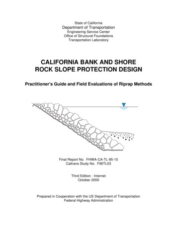
Highways), often called the "bank and shore manual" that introduced the CABS methodin 1960, we found the procedure unclear. Other reports also show the CABS rock-sizingequation, but none of them adequately describe the design procedure. Therefore, Chapter5 herein clearly presents the CABS layered RSP design method. Appendix A has solvedproblems and the corresponding problem-specific cross sections. Appendix B has portionsof the Caltrans Standard Specifications, as they pertain to Chapter 5 and Appendix A.This report is useful to engineers and practitioners for designing RSP bank andshore protection facilities, and to researchers as documentation for future evaluations ofRSP sites and design methods. While stone size and stream velocity are two importantfactors that contribute to the success or failure of RSP revetments, conclusions of Chapter2 and recommendations of Chapter 3 are based on critical evaluations of RSP revetmentsin the field, not only on theoretical stable rock size and velocity. The photographic studyin Appendix C highlights significant features of various RSP facilities that support ourfindings and clarify text. Chapter 4 presents a plan to implement the findings, Chapter 6documents the investigative process, Chapter 7 documents field reviews and evaluations,and Chapter 8 lists references with annotations by Racin about each document. Our keysources for evaluating the various RSP design methods are engineers and practitionerslisted in Chapter 9.Table 1-1 lists RSP design methods that were field-evaluated, were found effective,and are used in engineering practice among five states. In WA, OR, CA, CO, and MS, wefield-evaluated sixty-five RSP sites (Chapter 7 Table 7-2). The RSP facilities were eithersuccessful or had failed and were repaired. Our inquiry for site information (Chapter 6Exhibit 6-A) defines successful sites as having little or no maintenance after being exposedto design flows. Failed sites are characterized by frequent repairs after less than designflows. The oldest site we evaluated was built in 1948 and the most-recent in 1995; ourdatabase spans 47 years. Among 53 sites, the average useful service-life is more than16 years (unknown age at 12 sites). About one third of the sites needed some repair ormaintenance, however as of June 1996, all 65 sites are functioning well.The CODOT method is a variation of Reference 5 (Anderson et al, NationalCooperative Highway Research Program, NCHRP Report 108) and Reference 8 (Norman,"old" HEC-15). No RSP sites were found or field-evaluated that were based directly onReference 8 or Reference 11 (Chen & Cotton, "new" HEC-15). The design method inReference 2 (US Bureau of Reclamation, EM-25) is for stilling basins below dams and forculvert outlets, not for banks or shores. There were two sites in California that wereprobably based on Reference 9 (Roehl et al, ASCE Manual 54). A possible method in2
proposed Reference 15 (Blodgett & McConaughy) was not published, and no sites werebuilt by that method in time for field evaluations. Although widely published and cited, noRSP sites were field-evaluated that were based directly on Reference 10 (Simons &Senturk).Table 1-1. Field-evaluated RSP Design MethodsAbbreviation / Name of MethodBasisReferencevelocitytides, scourwave height1FHWA's HEC-11 / Federal Highway Administration'sHydraulic Engineering Circular No. 11velocity [A]3, 12CORPS / US Army Corps of EngineersEngineering Manual 1110-2-1601velocity [B]4CERC / US Army Coastal Engineering Research Center'sShore Protection Manualwave, tides45CODOT / Colorado Department of Transportationshear stress7velocity17CABS / California Bank and Shore - river equation" /"shoal water equation" /"deep water equationOR Keyed / Oregon Keyed RiprapDUDFCD / Denver Urban Drainage Flood Control DistrictvelocityNotes. [A] Converted from shear stress. [B] Formerly shear stress.55Costs for designing and building the RSP sites were usually not available. Inroadway and bridge work, few contracts are let exclusively for building RSP. Cost data areskewed by other items in bid packages, that is, in the competitive bid process rock pricescan vary widely, because rock may not have been the major item of work. Thereforerelative cost of an RSP facility was simply judged as either expensive or inexpensive bythe engineers and practitioners, who field-evaluated the RSP sites with us. Among sixtyfive sites in Table 7-2, eight were judged as expensive. A few contracts had claims, whichinflated costs of all items. For a few other sites, initial construction was not expensive, butthe sites were rated as expensive because of frequent maintenance. Hydraulic data werenot readily available to us for most sites, however, for a few sites we were given copies offormal hydraulic study reports. Despite gaps in cost and reported hydraulic data, enoughfield evidence was available to adequately rate each site in Table 7-2 and each RSPdesign method in Table 1-1.3
The CABS layered RSP design method is preferred on Caltrans projects. Othervalid RSP design methods are listed in Table 1-1, and the nearly identical Table 2-1 showsthe most recent editions of each reference. See Chapter 8 for complete bibliographicaldata. As-evidenced by field evaluations of RSP sites in Table 7-2 and other sites notincluded in this report, there are maintenance problems and failures with any RSP designmethod. Constructing layers of riprap, an adequate toe, and leading and trailing edges(also called cutoffs or flank treatments) are features that tend to assure riprap revetmentsthat will function well with infrequent maintenance.A poor practice for building an RSP facility is simply to place large rock that is sizedas the "outside" layer along an erodible bank without placing any "inner" layers. Suchpractice is probably justified as a flood-fight response, where large-sized riprap may be theonly material available, and when there is no time to properly construct a layeredrevetment. However, after floods recede, simply placing more large rock is poor practice.In those and similar bank protection efforts, if the bank fails, it is not necessarily the faultof the design method. Such practice will not work for long-term bank protection, becausewithout layers of adequate thickness and gradation, erodible bank materials will ultimatelypipe through voids and the bank will have failed again.Selecting the Investigative Process. We opted to do field evaluations insteadof theoretical "paper studies." The dependent variable of studying RSP design methodswould naturally be stone size, and the independent variable would be velocity. Threeapproaches were considered. The first approach was to measure rock sizes and velocitiesat several sites. That would require a long duration of observations at various sites,because velocity depends on more than just local geometry. Velocity depends on climate,runoff quantity, changes in river and stream morphology, and other hydrologic factors likechanges in watershed land uses, storage, and infiltration. A second approach was to buildside-by-side RSP revetments designed by various methods. It would have been veryexpensive to build several side-by-side revetments in different climates and hydrologicregimes, and we still needed a long duration of observations. Neither of these first twoapproaches were feasible, expedient, nor within the budget. The third approach weconsidered and decided on was to field-evaluate RSP sites with local engineers andpractitioners. These people had design, construction, and maintenance experience withone or more of the design methods, and they were familiar with RSP sites in theirrespective localities. We interviewed the engineers and practitioners, listened to theirnarratives, exchanged our views, recorded data, and photographed each RSP site. Afterassessing and rating the sites, we then judged the RSP design methods.4
While determining the success or failure of an RSP site initially seemed simple, wequickly discovered that people were reluctant to admit "failures." "Failure" had to bedefined. Therefore, we developed an inquiry for data and stated our definitions of successand failure (Exhibit 6-A). Inquiries were sent to engineers in WA, OR, CA, CO, and MS.Responses for successful and failed sites revealed that most sites are not normally fieldevaluated after they are built. The number and duration of flow events that exceed thedesign event are among data required for evaluating an RSP site, and hence the designmethod. Such hydraulic exposures are not routinely recorded, because RSP sites are notnormally instrumented. Therefore, sites for evaluation were selected by local engineersand practitioners among the five states, who were familiar with recent hydrologic/hydraulicevents, various RSP sites, and site-specific nuances.We developed a data guide with questions for field evaluations (Table 6-1) andrecorded data that were available. We audio-taped and later reviewed interviews with theengineers, practitioners, and other RSP researchers. We compiled an extensivephotographic record of RSP sites. To make and defend conclusions (Chapter 2) andrecommendations (Chapter 3), we condensed data from each site and present ourdatabase as Table 7-2. The determination of success or failure at each site was made byexperienced local engineers and at least two of the authors of this report. Each RSPfacility was evaluated with site-specific subtleties in mind and with the benefit of eachevaluator's additional nondocumented professional experience. We judged an RSPdesign method as effective (that is, valid, satisfactory, OK), as long as there was at leastone successful RSP site, and preferably several sites, to affirm our judgment.Critique of Investigative Process and CABS Design Method. Some reviewersof early drafts of this report looked for comparative calculations of stone size versusvelocity. Theoretical presentations of that kind were already done by several authors, thebest of which is in Reference 10 (Simons & Senturk). Other reviewers looked for"conventional data analysis" of site information: graphs, tables, and statistical routines.No conventional data analyses were done. Initially we thought we would find andassemble data that could simply be plugged into parametric and/or nonparametric routines.Instead we found that such data are sparse and not typically kept in design files, namelyvelocity, assumptions, and the method for arriving at riprap size. We found only a fewRSP-site evaluations in Reference 6 (Anderson) and Refer
C-8 Tree toppled by current C-4 C-9 Rock and tree stump retards (permeable jetties, groins) along levee, C-5 also called "fish habitat" or "fish cluster" structures C-10 Fish habitat structure C-5 C-11 Riprapped toe and plastic geogrid gabions C-6 C-12 Close-up of plastic geogrid gabion and vegetation C-6 C-13 Repaired zone where flow impinges C-7