Transcription
Wideband Control for MagnetronDriven CavitiesBrian Chase - FermilabMichael Read - Calabazas Creek Research Inc
Magnetron Collaboration Calabazas Creek Research Inc– Michael Read, R. Lawrence Ives, Thuc Bui Fermi National Accelerator Laboratory– Brian Chase, Ralph Pasquinelli, Ed Cullerton, Philip VargheseJosh Einstein, John Reid Communications and Power Industries LLC– Chris Walker, Jeff Conant Previous Collaboration with Muon’s Inc.Gregory KazakevitchBrian Chase LLRF2017 Barcelona10/17/17
Outline Demands for high power, high efficiency RF Vector control schemes for magnetrons Experimental results Ongoing researchBrian Chase LLRF2017 Barcelona10/17/17
Take-a-ways from the Proton Driver High EfficiencyWorkshop at PSI Proton Drivers:- GeV-energy range- MW-beam power range Applications: neutrinos, muons, neutrons, Accelerator DrivenSystems(ADS). Types of accelerators for proton drivers:- Cyclotrons and Fixed-Field Alternating Gradient accelerators (FFAG);- Rapid Cycle Synchrotrons (RCS);- High intensity pulsed linear accelerators;- CW Superconducting RF linear accelerators. High RF efficiency is critical for high beam power applicationBrian Chase LLRF2017 Barcelona10/17/17
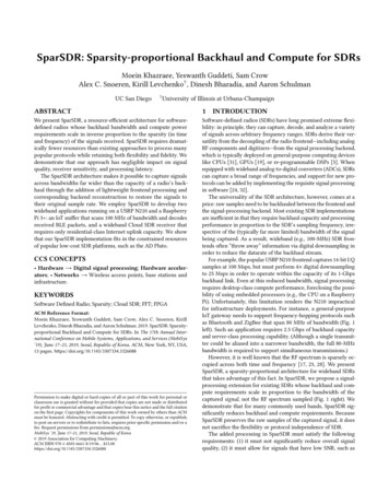
The basics of magnetron operationCathode at negative potentialaccelerates electrons outward.B field causes electrons to spiralE field across gaps causes bunching intoelectron cloud spokes. Rotating spokesintern excites cavities. RF power iscoupled out and is constant amplitude.Injection Locking:RF maybe driven in on same port andcause the spokes to phase lock up tosource providing low noise RFAmos DexterCross section of a cookermagnetron showing cathodeand RF cavitiesR. Adler, A study of locking phenomena in oscillators, Proc. IRE andWaves and Electrons, vol. 61, no. 10, pp. 351-357, June 1946.Brian Chase LLRF2017 Barcelona10/17/17
Magnetrons excel at many RF source requirements Power: 100 kW CW and MW scale pulsed operation– average power capability increase with lower frequency Efficiency: High power devices 85% at L-band Power supply voltage: typically 25kV Low cost: 0.50/watt at 100kW and 50 units Small size: 100 kW pulsed 1300 MHz tube is 1 foot high anddoes not require an oil tank They are easy to replace and rebuild and can be designed fora reasonably long life and low noise when injection locked However, they are basically a constant power device, not alinear amplifier like a klystronBrian Chase LLRF2017 Barcelona10/17/17
Industrial CW Magnetrons High power CW magnetrons used forindustrial heating are catalog items 85% efficiency typical 100 kW L-band - 18” length, 5” diameterBrian Chase LLRF2017 Barcelona10/17/17
Phase control loop around SRF cavityLancaster: Amos Dexter, Graeme Burt and Chris LingwoodDemonstration of CW 2.45 GHz magnetron driving aspecially manufactured superconducting cavity in a VTFat Jlab.Control of phase in the presence of microphonics wassuccessful.H. Wang et al., “USE OF AN INJECTION LOCKED MAGNETRON TO DRIVE A SUPERCONDUCTING RF CAVITY,” in Proceedings ofIPAC’10, Kyoto, Japan, THPEB067.Brian Chase LLRF2017 Barcelona10/17/17
Cascaded magnetrons and out-phasing AM controlConcept: cascade injection lockedmagnetrons to increase gain, combine twopairs to get amplitude control byoutphasing in pulsed mode operationOutcome: Proof of concept for cascadestage and the realization that we neededCW power supplies to make real progress.Strong belief that this scheme would workbut it does have its complexities.Grigory Kazakevich, et al. Muons Inc.Yakovlev, Pasquinelli, Chase, et al. FermilabBrian Chase LLRF2017 Barcelona10/17/17
Amplitude control by fast phase modulation techniqueMagnetrons are constant output power devices. However, the power in thecarrier destined for the cavity can be reduced by fast phase modulation,moving power from the carrier into discreet Bessel sidebands that are outsidethe cavity bandwidth. These sidebands will be reflected from the cavity andback to the circulator loadIncreasing the modulationdepth(137 degrees) suppressesthe carrier over a measured 64dB dynamic range in labBrian Chase LLRF2017 Barcelona10/17/17
Rejection of PM sidebands by Narrowband CavityWhile output power is constant, sinusoidal phase modulationcreates discrete sidebands at multiples of the modulationfrequency while the power shifted from carrier to sidebands isdetermined by modulation depthCavity responseFundamentalPM sidebandsAfBrian Chase LLRF2017 Barcelona10/17/17
Phase Modulation EquationsUsed for generation of amplitude-to-phase LUT. Generates a lookup table such that the regionBefore the first null in the Bessel is covered by the controller. Allows for linearization correctionsby just adding a scaling table.Brian Chase LLRF2017 Barcelona10/17/17
Bessel of the first kind, Region before first nullInverse function in look up table drives phase modulationdepth to linearize cavity driveBrian Chase LLRF2017 Barcelona10/17/17
LLRF controller for 2.45 GHz SRF cavity driven by 1.2 kWMagnetron using Fast Phase ModulationBrian Chase LLRF2017 Barcelona10/17/17
Controller architectureBrian Chase LLRF2017 Barcelona10/17/17
Injection Locked 2.45 GHz magnetron driving SRF cavityInjection Locked 2.45 GHz gnetron'Loaned'SRF'cavity'from'JLab'Tes ublished'in'JINST'Na onal'and'Interna onal'patents'pending'11!Brian Chase LLRF2017 BarcelonaRalph J. Pasquinelli P2MAC 2015!10/17/173/9/2015!
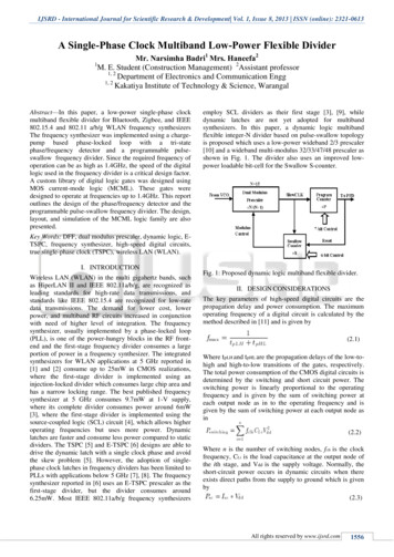
A0 VTS 2.4 GHz Magnetron - Cavity test results- Amplitude control shownlinear over 30 dB range- Moderate feedbackperformance demonstrated- 0.3% r.m.s, and phase stabilityof 0.26 degrees r.m.s.- Tests limited by extreme cavitymicrophonics and very limitedtime with the test caveBrian Chase LLRF2017 BarcelonaCavity at 4 K, LLRF drive. Blue loops open,Red loops closed and maximum output, Greenloops closed and amplitude reduced by 17 dBshows the PM modulation is effective foramplitude control.10/17/17
Phase Modulation Tests on 1300 MHz 9-cell Cavity 9 cell cavity is driven bya phase modulatedsource through a 4kWsolid state amplifier8/9 pi mode driven by carefully tuned 2nd sidebandForward power from SSABrian Chase LLRF2017 Barcelona8/9 pi mode is easily not excited by sidebands10/17/17
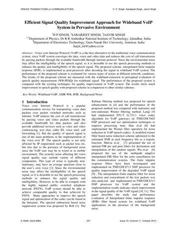
CCR / CPI - 100 kW Pulsed, 10 kW Ave. 1.3 GHz MagnetronCalabazas Creek Research IncPhase II SBIR grant to develop a 1.3 GHz, 100 kWpeak power, 10 kW average power magnetronstation in partnership with Fermilab andCommunications and Power Industries LLC, utilizinga full vector control scheme developed by Fermilab.254A Magnet Current20kV4.5A Magnet Current155A Magnet Current105.5A Magnet Current500246AmpsV-I Characteristics of Magnetron atVarying Electromagnet CurrentValues from initial short pulse tests.Brian Chase LLRF2017 Barcelona86A Magnet Currenttube 12” tall10/17/17
CCR 1.3 GHz 100 kW magnetron testing at HTS FermilabIsolator with shorting plateDiagnosticsand controlWater cooledloadHigh voltagemodulatornot shownKlystron100 kW MagnetronBrian Chase LLRF2017 Barcelona10/17/17
LLRF Digital Control Card for Phase Modulation Scheme(16) 14 bit ADCs (8)14 bit DACs System on ModuleDual core Armprocessorwith FPGA eliminatesthe need for a crateand externalprocessor.Brian Chase LLRF2017 Barcelona10/17/17
Testing Status Magnetron cart shipping and installed at HTS– Water cooling, 208VAC power, high voltage pulsed modulatorcabled 5 kW klystron CW powered up and driven with pulsed RF– Ready for safety review and testing with 22 kV modulator Near term plans are to fully characterize the injection lockedmagnetron– Power curves and efficiency– Magnetron self heating as a function of modulation depth andfrequency– Power supply sensitivity Drive 9-cell cavity when availableBrian Chase LLRF2017 Barcelona10/17/17
Magnetron Control R&D moving forward Cathode current control is a logical choice for slow amplitudecontrol to optimize efficiency for operating conditions– there is potential for moderate bandwidth with switch-mode PS– should be a part of any scheme Vector addition and out-phasing of two magnetrons should work formost designs– at the cost of hardware complexity and moderate control complexity RF vector control through fast phase modulation is a potential fit formany machine designs– single tube design with greatest hardware simplicity– at the cost of control complexity All techniques need development time on a stable test platformBrian Chase LLRF2017 Barcelona10/17/17
Summary The magnetron has been a remarkable RF source for 75 years thatis unparalleled in cost and highly efficient. It is widely used forindustrial heating and smaller electron accelerators but has hadlittle impact in hadron accelerators There are now several control architectures that can takeadvantage of the processing capabilities of modern FPGAs Testing is in progress with1.3 GHz 100 kW 10% duty factormagnetron and controller using fast phase modulation. Magnetrons may be a strong contender for high power, highefficiency acceleratorsBrian Chase LLRF2017 Barcelona10/17/17
Thank you for your attention!Brian Chase LLRF2017 Barcelona10/17/17
Backup slidesBrian Chase LLRF2017 Barcelona10/17/17
References B. Chase, R. Pasquinelli, E. Cullerton, and P. Varghese,“Precision Vector Control of a Superconducting RF Cavitydriven by an Injection Locked Magnetron,” Journal ofInstrumentation, no. 10 P03007, 2015. H. Wang et al., “USE OF AN INJECTION LOCKEDMAGNETRON TO DRIVE A SUPERCONDUCTING RFCAVITY,” in Proceedings of IPAC’10, Kyoto, Japan,THPEB067.Brian Chase LLRF2017 Barcelona10/17/17
Efficiency Goals For high power SRF linacs the RF sources are a keycomponent in overall wall-plug efficiencyBrian Chase LLRF2017 Barcelona10/17/17
Amos DexterBrian Chase LLRF2017 Barcelona10/17/17
A0 Vertical test stand, Jlab 2.45 GHz single cell undressedcavity RF block diagram Fig1.jpgBrian Chase LLRF2017 Barcelona10/17/17
1950s transmitter using 2 magnetrons and out-phasingPatent awarded in 1952 for a transmitterdesign using cathode voltage modulationand out-phasing with two magnetronsWhy was this technology discarded?- Possibly just too many parts andexpense.Brian Chase LLRF2017 Barcelona10/17/17
station in partnership with Fermilab and Communications and Power Industries LLC, utilizing a full vector control scheme developed by Fermilab. 0 5 10 15 20 25 0 2 4 6 8 4A Magnet Current 4.5A Magnet Current 5A Magnet Current 5.5A Magnet Current 6A Magnet Current V-I Characteristics of Magnetron at Varying Electromagnet Current