Transcription
SLAC-R-1037SPS Wideband Transverse Feedback Kicker:Design ReportSLAC National Accelerator Laboratory, Stanford University, Stanford CA 94309Work funded in part by DOE Contract DE-AC02-76SF00515 and LARP.
SPS Wideband Transverse Feedback Kicker: Design ReportJ. M. Cesaratto, J. D. Fox, and C. H. RivettaAccelerator Research Department, SLAC National Accelerator Laboratory, 2575 Sand Hill Rd. Menlo Park, CA 94025D. Alesini, A. Drago, A. Gallo, F. Marcellini, and M. ZobovINFN-LNF, Via E. Fermi, 40 00044 Frascati (Roma), ItalyS. De Santis, Z. Paret, A. Ratti, and H. QianLawrence Berkeley National Laboratory, 1 Cyclotron Rd. Berkeley, CA 94720H. Bartosik, W. Hofle, and C. ZanniniCERN, Geneva, Switzerland(Dated: September 9, 2013)The SPS wideband transverse feedback system is being developed to control vertical beam instabilities arising from intensity dependent effects like electron cloud instability (ECI) and the transversemode coupling instability (TMCI). As part of the LHC Injector Upgrade (LIU) project, a widebandkicker is necessary as a damper to control unstable modes within a bunch. Several types of kickerstructures, including cavities, striplines, and slotted structures have been studied to evaluate theoperating bandwidth, transverse shunt impedance, and beam coupling impedance. Studies and results from all structures are described below, including three potential paths to implement thesestructures as a wideband kicker system. A single, slotted-coaxial kicker of 1 m length providessubstantial kick strength (integrated transverse voltage) over a bandwidth ranging from nearly DCto 1 GHz. An array of four 10 cm long striplines provides substantial kick strength from DC to 750MHz. For a given amplifier power of 500 W, the array of striplines can provide twice the transversedeflecting voltage as the slotted kicker for frequencies up to 200 MHz. At frequencies 800 – 1000MHz the transverse voltage generated by the slotted kicker dominates that of the stripline array. Werecommend to CERN that both the slotted-coaxial kicker and the array of striplines should undergomore detailed mechanical design and be built as prototype wideband kickers for installation in theSPS.I.INTRODUCTIONCurrent plans for the HiLumi phase of LHC operation require an investment into upgrading the accelerators along the injector chain in the frame of the LHCInjector Upgrade (LIU) project [1–3]. This report concerns the last accelerator in the chain, the Super Proton Synchrotron (SPS). The purpose of this report isto establish a baseline for possible implementation of atransverse (vertical) kicker in conjunction with a wideband feedback system in the SPS to control beam intensity dependent instabilities caused by electron cloud(ECI) and transverse mode coupling (TMCI). The kicker(damper) structure is a critical component in this feedback loop, as it applies the wideband correction signalback onto the beam. The kicker options are evaluatedvia electromagnetic simulation considering the parameters of operating bandwidth, maximum transverse shuntimpedance, and broadband beam coupling impedance.Additional aspects such as fabrication complexity, vacuum compatibility, and ease of coupling to external amplifier systems are also considered, but require more detailed mechanical design and consideration. From theinformation available, we have provided several solutions Electronic address: cesaratto@stanford.eduwith frequency response up to 1 GHz. The required kickstrength necessary has been estimated on the order of10 5 – 10 4 eV · s/m. The kicker must reside within thebeam line vacuum system so the dimensions, aperture,and/or electrodes shall comply with all SPS stay clearlimits and length limitations. The number of kickers orkicker signals and load ports is an important operationalconsideration, as every independent element that must bekept in precision timing with the beam adds operationalcomplexity. This report explores three possible technicalimplementations of a kicker for the SPS transverse highbandwidth feedback system, and highlights the advantages and disadvantages of each.A.Wideband Feedback OverviewThe instability control problem requires technology tosense beam motion, compute a useful correction signal,and apply the correction signal back onto the particlebeam. The beam physics determines the beam dynamics and issues of stability. The purpose of the feedbacksystem is to change the beam dynamics to a stable casefor all the operating parameters of the accelerator (energy, beam current, filling pattern, electron cloud density, HOM impedances, etc.). The feedback system musthave sufficient bandwidth to sense and correct motion
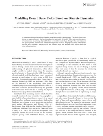
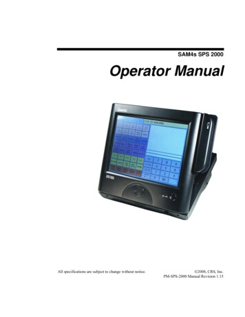
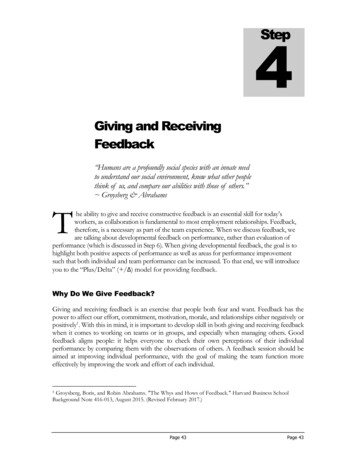
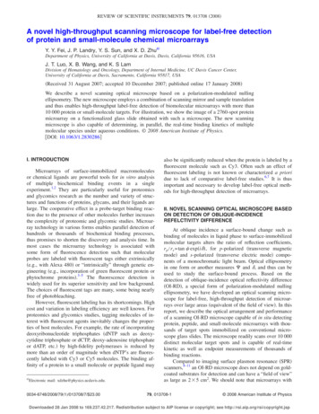
2within the individual bunches in order to correct theintra-bunch motion of ECI and TMCI. This is challengingfor pickup and kicker structures, which must have usefulbandwidths, and reasonable phase responses over roughlya gigahertz for the SPS cases. This large bandwidth isalso challenging for the signal processing, which musthave A/D and D/A functions with 2 – 8 GHz samplingrates, and support the computation of correction signalsat these high throughputs. The basic formalism, which isin development at SLAC, can generate useful correctionsignals for both coupled-bunch and intra-bunch instabilities anticipated for the SPS through the HiLumi upgradeof the LHC.B.impedance impact.Evaluation and analysis of each of these structures areprovided in this design report for their operational bandwidth, transverse shunt impedance, and in two cases,beam coupling impedance. Operational use and fabrication complexities will be evaluated for all designs. Eachmust comply with the existing SPS restrictions and constraints. The report will include three potential paths forfabrication weighing the advantages and disadvantagesof each. Finally, the report will conclude with a recommendation with respect to the three proposed paths fordetailed development and design of a vacuum compatibleprototype for beam tests in the SPS after Long Shutdown1 (LS1).Potential Kicker StructuresThree potential structures have been studied for use askickers in the SPS. Stripline kickers have been used in thefield for many years and have well established properties.They are attractive for their high shunt impedance atlow frequencies, and they have DC response when usedtransversely. They can be tapered to provide continuous frequency response, but their ultimate band coverage and maximum shunt impedance are determined bytheir length. Generally speaking, shorter striplines willextend to higher bandwidth, but will have lower shuntimpedance. They can be used in arrays to increase theshunt impedance with appropriate delay and synchronization between multiple striplines.Cavity kickers are attractive for their high shuntimpedance, although they are relatively narrowband.However, by damping the cavity, the Q can be reduced,thereby increasing the bandwidth. Depending on the geometrical design of the cavity the band of coverage canbe adjusted. Multiple bands of cavities would be necessary to cover the full band necessary, which could lead tocomplexity in the signal processing, phasing, and equalization.Slotted or slotline kickers similar to those used inthe CERN ISR and p̄-complex [4] and Fermilab p̄Accumulator [5] for stochastic cooling are also considered. These structures couple power from waveguides ortransmission lines to the beam pipe via small periodicslots. These structures can be tuned dimensionally toprovide the necessary bandwidth and shunt impedance.Like any of these structures, installation into the machine will contribute to the beam coupling impedance ofthe machine. Since these structures have many small periodic slots they must be studied carefully for the beamC.Existing SPS Parameters and Constraints1.Installation LocationFigure 1 shows a schematic view of the layout of theSPS (see Ref. [6] for a scaled version with transfer linesshown). The proposed location for the new widebandkicker will be in Long Straight Section 3 (LSS3) of Sextant 3 in the SPS. This region marks the start of the arcin the dispersion suppressor region of the machine, containing flat vacuum chambers. The 13 m long locationwhere the kickers will be installed is shown in Fig. 2. Because of beam aperature (stay-clear) requirements, onlyabout 8 m of the space is usable (see Sect. I C 2). LSS3is a low radiation area of the SPS with existing RF infrastructure. Cabling and preparation of the space hasbegun as a part of LS1 work. Preparing the space willinclude reshuffling equipment in LSS3 and installing adummy chamber if the new kicker is not installed by thetime the SPS becomes operational again at the end ofLS1. As an alternative location, LSS5 has also been considered, but it does not have existing RF infrastructure.In LSS5 an experimental chamber would be available toinstall auxiliary equipment such as power amplifiers.2.Beam ApertureBeam aperture studies have been performed byCERN’s ABP group in order to estimate the transversebeam stay clear region for the new kicker. The aperturecan be estimated by the following expression qqAx (s) xco (s) co βx (s)/β̂x (1 kβ ) Dx (s) kDx D̂x βx(s)/β̂x δ̂pax (s) (1 kβ ) βx (s) xwhere ax is the available aperture (normalized to theRMS beam size) for direction x, Ax is the physical aper-(1)ture, xco is the closed orbit, co is the maximal closed
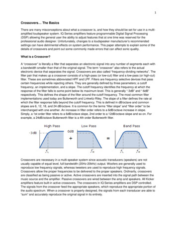
3resents a linear interpolation between QF and the MBBdipole aperture to stay completely in the shadow whereasthe second, in red, shows the aperture required for theCNGS beam with Q20 optics1 . In the vertical plane, theaperture half width is constant at 20 mm, which is justslightly larger than the MBA vacuum chamber height of39.3 mm. Horizontally, the aperture half width is smallerat MBB.32150 at 55 mm. As one moves away from dipolemagnet, the aperture increases and at 8 m downstreamthe aperture half width is 66 mm. Thus, the new kickerswill have an aperture that must be larger then 40 mmin the vertical direction and 132 mm in the horizontaldirection.Kicker aperture requirements80Aperture half width (mm)70FIG. 1. Layout of the SPS. The proposed location for installation of the new wideband kicker will be in LSS3 of Sextant3. LSS5 is also considered as an alternative location for installation.6050Horizontal (in shadow of local aperture)Horizontal (CNGS in Q20 optics)Vertical40302010002468101214Distance from MBB.32150 (m)FIG. 3. Calculated aperture requirement for the kicker withinthe installation region of LSS3.3.FIG. 2. Precise location in LSS3 of the SPS where the newkicker system will be installed. About 13 m of longitudinalspace is available, but only about 8 m of that space is usablebecause of beam aperture (stay-clear) considerations.orbit distortion, βx is the beta function, βˆx is the peakbeta function, Dx is the dispersion, Dˆx is the peak dispersion, kβ is the beta beat factor, kDx is the dispersion beatfactor, x is the physical emittance, and δ̂ is the peak momentum spread. Following a conservative approach, estimates were calculated to stay in the shadow of the localaperture restrictions. In the horizontal plane, there aretwo choices, as shown in Fig. 3. The first, in blue, rep-SPS Operating ModesThe RF frequency of the SPS is 200 MHz, with a smallcomponent at the 4th harmonic at 800 MHz added bydedicated cavities. The 200 MHz RF system defines anRF bucket width of 5 ns length and harmonic numberof 4620. The typical bunch length is represent as 4σz ofa normal distribution, where σz ' 0.7 ns at injection energy (26 GeV). The bunch length becomes shorter duringacceleration to flat top (450 GeV) where σz ' 0.4 ns.Up to now, the operational LHC beam had a bunchseparation of 50 ns. The bunch intensity for typical 50ns spaced beam was 1.7 1011 p ( rmsx,y 1.7 µm) andbecause of higher bunch intensity and lower emittance,1The Q20 optics are not presently used for the high intensityCNGS beam but could be considered for operation with highintensity fixed target beams in the future. Since the Q20 opticshas higher beta functions and dispersion function compared tothe SPS design optics (Q26), the aperture calculations presentedhere were performed with the Q20 optics.
4the high energy physics experiments experienced pile-up.Thus, to reduce pile-up at increased luminosity, the goalis to run at 25 ns bunch spacing. Table I contains a listingof the bunch intensity, emittance, and bunch length at450 GeV for present and future LHC beams.The filling scheme for LHC beams, populates everyfifth bucket, leaving a 25 ns bunch spacing or a bunchrepetition rate of 40 MHz. Typically, each full batchconsists of 72 bunches, with at most 4 batches acceleratedin a single SPS ramp cycle, each batch separated by 45buckets. Thus, up to 288 bunches may be present inthe machine2 . The typical bunch intensity today for 25ns spaced beams is 1.2 1011 p at extraction. Notice thatHL-LHC beams call for nearly twice the bunch intensitiesof today, and the kickers and loads must be able to handlesuch beam induced power.One disadvantage of using 25 ns beams is evidence ofEcloud effects, which include vacuum pressure rise, transverse instabilities, losses, and emittance blow-up. As amethod to mitigate electron cloud, scrubbing runs havebeen performed over the years with 25 ns spaced beams.Recently, a doublet scrubbing beam has been studied andshows high scrubbing efficiency [7]. This type of beamcontains 25 ns spaced bunch doublets, with the doubletsspaced at 5 ns.TABLE I. Present and future LHC beam parameters for standard production injection fills (beam energy 450 GeV) [8]. Blis the 4σz bunch length.5025LIU2550HL-LHC25AchievednsnsnsnsnsN (1011 p/b) rmsx,y (µm) z (eVs) Bl 53.682.500.51.652.322.080.451.554.Existing SPS FeedbackThe existing SPS vertical feedback operates with twokicker deflectors kicking with the electric field only, installed at a β 42 m in point 2 of the SPS [9]. Eachkicker has a length of 1536 mm, and is operated by apower amplifier with two 30 kW tetrodes in push-pullconfiguration developing a maximum of 2.6 kV over thegap of 38 mm. The combined transverse kick voltage forlow order coupled bunch modes is 215 kV correspondingto 7.2 10 4 eV·s/m and can damp injection errors on theorder of several millimeters within 20 turns. At 20 MHz,2For purposes of non-LHC beam e.g., scrubbing beams, morebatches may be injected with higher repetition frequency, butat reduced bunch intensitiesthe maximum operating frequency, the kick strength isreduced to 1.58 10 4 eV·s/m.At first glance, it appears that the new transversedamper must reach as low as 40 MHz (the bunch repetition frequency for LHC beams), in order to kick everybunch of the 25 ns spacing regime. But, the new scrubbing beam presents a situation where a bandwidth of 20– 100 MHz would be necessary with the 5 ns doubletspacing to cover all possible coupled bunch modes. If thetwo bunchlets oscillate out of phase, there is currently nosystem to correct this, so there is a desire that the newwideband damper overlap in frequency with the existingtransverse damper at the low frequency end.5.Transverse Beam OffsetThe kicker structure must be able to provide a reasonably uniform kick over the region in vacuum space thatthe beam may reside. Initially, we have been providedestimates of a worst case scenario, a 5 ns beam with theQ20 optics and 3.5 µm transverse emittances. Vertically,the good field region should be 15 mm from the axis.Horizontally, it depends on how close the kicker is installed to the MBB dipole, but for a 1 m long kicker, 25 mm from axis may be sufficient. Considering theentire available space the requirement is 40 mm.6.SPS Transverse Impedance BudgetThe effective beam impedance [10] of the new wideband kicker should be compared with the effectiveimpedance of the installed devices. The total measuredeffective vertical impedance of the SPS is around 18MΩ/m [11]. Based on 3D simulations, coaxial wire measurements, beam-induced heating measurements and history of the measured effective vertical impedance, thekickers are the most important contributors (around 7MΩ/m) [11]. Presently, there are 19 kickers installed inthe machine, with an average contribution per kicker of 0.37 MΩ/m. The beam coupling impedance of the newwideband kicker should not exhibit narrow resonancesand must contribute less than the average impedance perkicker. Preferably, the beam coupling impedance shouldnot exceed about 1% of the total SPS impedance, i.e., 0.18 MΩ/m.7.Existing Tapered Stripline Operated as a KickerThe existing kicker currently in use at the SPS for thewideband feedback development effort is a tapered exponential stripline pickup, developed in the 1970’s forbeam instrumentation purposes, and installed backwardsfor historical reasons [12]. The stripline consists of fourelectrodes exponentially tapered in width and in distance
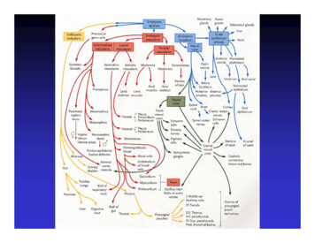
5from the vacuum chamber wall to maintain a 50 Ω characteristic impedance. When used as a kicker, the frequencyresponse rolls off at f0 158 MHz. For the feedbackdemonstration experimental setup, with a 100 W amplifier powering each electrode, a momentum change, p 4 10 6 eV · s/m is generated (empirically determined)corresponding to a transverse deflecting voltage of V DC 1.2 kV at DC. Folding in the frequency response, thetransverse voltage on axis is shown in Fig. 4 and represented asV V DC1 hiω(βva/2L)1 e a e iωL/βvi(2)where v is the velocity of the beam, a 2.485 is theattenuation constant of the taper, and L is the 0.375m electrode length [12]. It is clear that a structure isneeded, which will extend to higher frequency and stillprovide sufficient kick strength. As a guideline (stillvery much under study), we desire a momentum changegreater by about an order of magnitude, 5 10 5 eV ·s/mover the present stripline’s performance. We will use thetransverse voltage of the existing exponentially taperedstripline as a baseline for comparison to the new kickerdesigns.A.BandwidthThe operating bandwidth is required to be very largeto provide bunch to bunch kicks as well as intra-bunchkicks. The modes that drive the bunch unstable are stillunder study, so a requirement on the upper frequencyneeded is still being refined, but at this time a goal of 1GHz has been set. A lower frequency bound of 10 MHzseems necessary to overlap with the existing transversedamper for the scenario of beam scrubbing, as describedin Sec. I C.B.Transverse Shunt ImpedanceThe transverse shunt impedance, R T 2 , of a kickerrelates the ratio of the square of the structure’s voltageto twice the total input power Ptot , according to [13]R T 2 V 22Ptot(3)where T is the transit-time factor, representing the reduction in integrated kick by not experiencing the maximumfield everywhere within the kicker. V is the transversevoltage and is defined as1.41.23 dB1V (kV)were tailored in simulation to be consistent with the SPSconstraints and system requirements.ZV (x̂, ŷ) 00.8L(E v B) dz.(4)Equation 4 in our case can be simplified as0.6Z0.4V V (ŷ) L[Ey (z) cBx (z)] ejωzβcdz(5)00.20 110210310Frequency (MHz)FIG. 4. Transverse deflecting voltage generated on axis by theexisting exponentially tapered stripline powered by four 100W amplifiers. The 3 dB roll-off point at 158 MHz is indicatedby the vertical dashed line.II.KICKER DESIGN CRITERIA ANDEVALUATIONThe structures were evaluated with respect totheir characteristics of bandwidth, transverse shuntimpedance, and beam coupling impedance via electromagnetic simulations. The parameters of each structurewhere the beam propagates in the z-direction, Ey (z) andBx (z) are complex fields in the vertical and horizontaljωzdirections, respectively, e βc accounts for the beam transit time and has positive argument if the electromagneticfield co-propagates with the beam and negative argumentif the field counter propagates with the beam, and L isthe length of the structure. This resulting voltage yieldsthe maximum vertical kick of the structure, which whenused in conjunction with Eq. 3 shows that for maximumtransverse voltage or kick strength, the shunt impedancemust be maximized.C.Beam Coupling ImpedanceAs a charged beam moves through an accelerator, itwill induce electromagnetic fields within the surroundingconducting vacuum pipe, which can affect the dynamicsof the beam. Analysis in the time domain yields these
6fields, known as wake fields. The wake potential is themomentum change of the beam from the induced fields.The wake function is the wake potential normalized tocharge, has units of V/C, and can be expressed longitudinally by W m (z) and transversely by W m (z), where mis the moment of the wake function. In the frequencydomain, the Fourier transformation of the wake functionyields the beam coupling impedance, longitudinally, inunits of Ω and transversely in units of Ω/m for the firstand second order impedances, respectively. The longitudinal and transverse coupling impedances can be represented respectively asZ (ω) Z (ω) D.1βcR jβcR W (z)eW (z)e jωzβc jωzβcdz(6)dz(7)Electromagnetic CodesThe electromagnetic calculations for the evaluation ofthe structures were carried out numerically using codesACE3P [14], GdFidL [15], HFSS [16], and CST [17].GdFidL and CST are time domain based codes whileHFSS is a frequency domain based code. ACE3P contains a suite of codes computing in both the time andfrequency domain.A.Cavities are rather narrowband structures, so tobroaden the frequency coverage we suggest to use severalcavities at multiples of a fundamental angular frequency,ω0 2π/τb , where τb 2.5 ns (estimate at 26 GeV) isthe bunch length ( 4σz )3 . Since low frequency cavitiestend to be large in size, a stripline kicker with frequencyresponse from DC to the fundamental frequency will beused in addition to the cavities.As an example implementation we propose to use astripline kicker covering the range from DC – 400 MHz,and two transverse cavities centered at the second andthird harmonics with bandwidths on the order of thebunch repetition frequency, fb 40 MHz. A preliminary estimate of transverse shunt impedances of cavitykickers can be extrapolated by scaling results reported inthe literature. The stripline has a length of L 0.17 mand an electrode separation of h 0.045 m, to complywith the stay-clear requirement. The proposed system issummarized in Tab. II. Assuming that each kicker listedTABLE II. Proposed stripline-cavity system as an intra bunchkicker. The values here are scaled results from the literature.TypeStripline Cavity #1a Cavity #2aBandwidth (MHz)DC - 400800(16)1200(16)Length (cm)171510Filling time (ns)0.61010QL2538Shunt Impedance (kΩ) 5.7 at DC1.52.2aIII.Stripline and Two CavitiesThe cavities operate with TM110 deflecting mode.DISCUSSIONThe three structures explored in this study each haveadvantages and disadvantages with regard to the characteristics necessary for the feedback system. In thissection we evaluate three possible implementations ofthese structures since covering such a large bandwidthwith sufficient shunt impedance is a tall task for a singlestructure. The three possible paths for implementationexamined are 1.) a stripline with two narrowband cavities, 2.) an array of striplines, and 3.) a slotted-coaxialkicker. Additional details on the properties of each structure alone are included in the Appendix for further reference.We would like to explain our nomenclature for poweras it relates to the transverse voltage estimates. We willdenote power in terms of the total power delivered to akicker system, Ptot , as is used in Eq. 3. The power peramplifier is also used and will be represented as, Pamp .For a single stripline with two electrodes, two out of phaseamplifiers are used and the total power becomes Ptot 2 Pamp . For a single slotline the situation is similar, andfor a single cavity typically one narrowband amplifier iscavcavused so Ptot Pamp.in Tab. II is powered by a 1 kW source covering theentire bandwidth, the resulting transverse voltage transferred to the beam as a function of frequency is shown inFig. 5. Simulations of the cavities verify that the desiredparameters listed in Tab. II are feasible (see Sec. A 2).An attractive feature of this type of scheme is thatvery wideband kicker(s) and amplifier(s) are not necessary. However, this scheme would require N narrowbandkickers and amplifiers to provide the overall required system bandwidth. The N narrowband kickers must thenbe timed and phased properly. The drive signal to theamplifiers requires N channel outputs from the processing of N frequencies. The input sequence requires DFTor FFT decomposition to identify each frequency, whichare computationally intensive procedures. In addition,the output signals for each cavity would be played outat a different rate than the input signal at 40 MHz. For3Note that this only an example. The bunch length is assumed tobe fixed in this case, which is not the case for operational beams.When the beam length changes, the frequencies needed to kickwill also change.
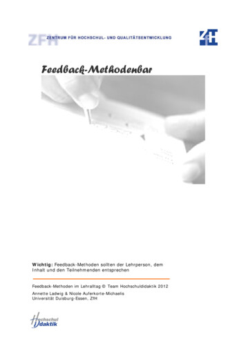
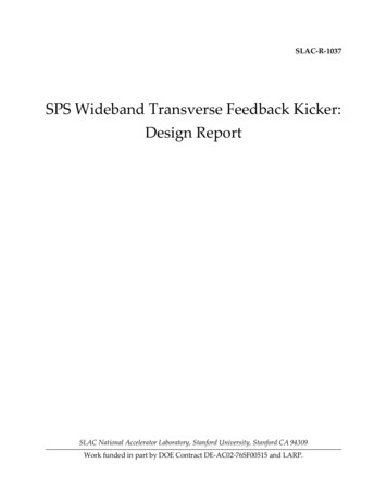
73.5f03V (kV)2.521.53f02f010.50 110the square root of the amplifier power, and amplifier costscales at least linearly with the amplifier power, it canbe shown that as long as the cost of a single amplifier iscomparable with the cost of a stripline module (which istrue except than for rather low powers), then the solutionwith lower power amplifiers and more modules is the costeffective one. Using a 10 cm long stripline optimizes theimpedance at 750 MHz, while still supplying a 1.8 kΩshunt impedance at low frequency for each kicker moduleand in our judgment this appears to be the best solutionfor the stripline length, balancing required power andnumber of kicker modules as shown in Eq. 8 derived fora SPS vertical stay-clear of 45 mm: p pc1e c Nk e 2 eff8.4 L(cm) Ptot2 R T Ptot010Frequency (GHz)(8)whereFIG. 5. Transverse deflecting voltages on the beam as a function of frequency for the stripline-cavity system assuming 1kW power over the entire frequency span. f0 indicates the 3dB roll-off point for the stripline at 400 MHz, and 2f0 and3f0 indicate the two cavities’ operating frequencies.LHC type beams, the 25 ns between bunches would beneeded to fill the cavity kickers. With the doublet scrubbing beam this would not be possible since the spacingis 5 ns and the filling times for the cavities are 10 ns.The processing involved for this type of modal systemis intensive and does not follow the present time-domain,single output channel approach that has been undertakenwith the feedback demonstration system to date. We feelthat although this is a very interesting approach, considering the processing hardware developed so far, and thecomplexity of synchronizing multiple kickers, that havinga single channel system over the entire band is a very desirable feature. With that in mind, we suggest two moresolutions, which are in tune with the present processingarchitecture.B.Array of 10 cm StriplinesA stripline shorter than the one mentioned in Sec. III Ahas a frequency response that extends across the entirefeedback bandwidth, without recourse to cavity kickers.The drawback is reduced shunt impedance, which scaleswith the square of the length, L, so that multiple kickermodules have to be used in order to keep the power perstripline down to a manageable level. This solution offers the advantage of being able to reach the desired momentum kick by simply increasing the number of kickermodules, while maintaining the amplifier power at a convenient level. On the other hand, a compromise betweenthe number of modules Nk and total space occupied bythe kicker system is the main limiting factor.Since the number of modules scales with the inverse ofLeff(cm) Lsin(ωL/c)ωL/c(9)is the stripline physical length, expressed in centimeters,corrected by an impedance roll-off factor, which is equalto 1 at DC and goes down to about 0.5 at 1 GHz.Figure 6 shows the integrated transverse deflectingvoltage for a four module kicker, where each moduleis driven by two 500 W maximum power amplifiers, ingreen, and by two 100 W, in red. Such a number ofmodules can be installed in a less than 1 m long portionof beam pipe and therefore provides a direct comparisonwith the 1m long slotted-coaxial structure described inSec. III C and particularly Fig. 7. It is worth pointingout that this stripline array makes use of eight amplifiers, whereas the slotted structure uses two amplifiers.Compared with the existing tapered stripline using 100W amplifiers, the array of striplines supersedes in integrated transverse voltage over the entire frequency span.At low frequency the voltage is a factor of 3.5 larger whileat 1 GHz provides 1.5 kV deflecting voltage.From Fig. 6 we can see that the voltage provided atlower frequencies is about one half of the voltage requiredto achieve 5 10 5 eV·s/m (15 kV) transverse momentumkick using two 500 W amplifiers. From Eq. 8 we can seethat in order to provide the entire kick strength at lowfrequencies, either the number of elements Nk has to bedoubled, thus increasing the overall length to over 2 m,or the amplifier power has to be increased four-fold, or acombination of the two.If we look at the high frequency end of the striplinearray response, we see that an additional factor of twowould be necessary to reach the nominal momentum kickat 1 GHz. Again, one has to consider what the actualrequired kick is and how practical it would be to increasethe number of elements and/or the amplifier power. Onecould also consider splitting the bandwidth into a lowerpower amplifier up to 500 – 600 MHz and a higher-poweramplifier for the frequencies up to 1 GHz.As opposed to the stripline and two cavity scenario, nospecial synchronization is required in this case, since it is
8154 striplines, P 100 W, P 800 W4 striplines, P 500 W, P 4000 WampamptottotV (kV)1050 1
The SPS wideband transverse feedback system is being developed to control vertical beam instabil-ities arising from intensity dependent e ects like electron cloud instability (ECI) and the transverse mode coupling instability (TMCI). As part of the LHC Injector Upgrade (LIU) project, a wideband