Transcription
Fermi National Accelerator LaboratoryPixel Detector Module for the BTeVExperiment at FermilabS. ZimmermannFermi National Accelerator LaboratoryBatavia, IL 60510 USAzimmer@fnal.govPixel 2002September 9-12, 2002
Fermi National Accelerator LaboratoryOutline BTeV Pixel detectorSome design constraintsCablingPixel half detectorPixel module readout schemePixel module prototypesConclusionsPixel 2002S.ZimmermannPixel Detector Module for the BTeV Experiment atFermilab2
Fermi National Accelerator LaboratoryBTeV Pixel Detector 22 million pixel channels. 30 pixel detector stations. Each pixel station consistsof 48 pixel modules. Each pixel module consistsof either 4, 5, 6, or 8 FPIXreadout chips and siliconsensors.Pixel 2002S.ZimmermannPixel Detector Module for the BTeV Experiment atFermilab3
Fermi National Accelerator LaboratorySome Design Constraints High readout efficiency required – Data is used in lowest level BTeVtrigger to reconstruct tracks.CablingHigh radiation environment – Must use rad-hard components ASICs.Inaccessible – Motivation for designing a reliable/robust readout.HDI and flex cable features –a) Constrained by feature size of flex technology.b) Limited width to avoid interference with adjacent modules need to minimize number of lines.c) Small production quantities (by industry standards)Cable Bandwidth – Limits data readout speed.CostPixel 2002S.ZimmermannPixel Detector Module for the BTeV Experiment atFermilab4
Fermi National Accelerator LaboratoryCablingPixel 2002S.Zimmermann Several detectors coverforward direction between10-300 mrad The volume outside thisregion is not instrumented. We can add mass to regionnot instrumented Proposal: use coppercables to control andreadout the Pixel modules.Pixel Detector Module for the BTeV Experiment atFermilab5
Fermi National Accelerator LaboratoryPixel Half Station Modules are a sandwich ofFPIX readout chips, siliconpixel sensors, and highdensity flex circuit (HDI). High density flexcircuit bringspower, control anddata signalsto/from FPIXchips.Pixel 2002S.ZimmermannPixel Detector Module for the BTeV Experiment atFermilab6
Fermi National Accelerator LaboratoryPixel Half Detector: Point-to-point readoutFeedthroughBoardHalf stationFlex cablesConnectors to PDCB FPIX2 HDI Flex cables Feedthrough Board 10 mtwisted pair Pixel Data Combiner Board (PDCB)Pixel 2002S.ZimmermannPixel Detector Module for the BTeV Experiment atFermilab7
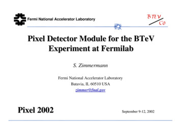
Fermi National Accelerator LaboratoryReadout: Simulations 1st step in design process is to understandhow much data needs to be moved out ofthe FPIX core. Average core data rates for worstcase module (module closest tobeam) based on GEANTsimulation. Luminosity (L): 3 nominal(nominal 2 1032/cm2sec)-0.16cm 0.76cmChip 1Chip 21.68cmChip 32.60cmChip 43.52cmChip 54.44cmChip 6664Mbps 443Mbps 187Mbps 84Mbps 45Mbps 35MbpsBeam @ 0cmPixel 2002S.ZimmermannPixel Detector Module for the BTeV Experiment atFermilab8
Fermi National Accelerator LaboratoryReadout: Design Solution – Key Features All signaling is low voltage differential (LVDS) – Immune tocommon mode noise, easy to drive 10m, and can be driven and receivedby today’s FPGAs. Data paths are point to point for reliablity. Data is serialized – Core data word is formatted then serialized tosave data lines. Configurable number of serializers (6, 4, 2 or 1) – High datarate chips with 6 serializers while lower data rate chips use a few as 1serializer. Match core bandwidth to total bandwidth of serializers – Coreoperating frequency depends on configuration. Simple word alignment scheme for receiver.Pixel 2002S.ZimmermannPixel Detector Module for the BTeV Experiment atFermilab9
Fermi National Accelerator LaboratoryReadout: Verilog Simulations DetermineOptimal Configuration Simulations ( 3000 crossings, 6500 hits) were run on Verilogmodel of FPIX core to determineminimum number of serializerswhile still maintaining highreadout efficiency.Hits (approx.)# SerializersEfficiency @nominal LEfficienct @ nominal L3 Pixel 2002S.ZimmermannChip 16400699.7%Chip 242506100%Chip 317004100%Chip 48002100%Chip 54501100%Chip 63501100%98.0%99.6%99.6%99.9%100%99.7%Pixel Detector Module for the BTeV Experiment atFermilab10
Fermi National Accelerator LaboratoryReadout: Data Latch Clock and Example WaveformWord NWord N 1Word N 2Ser6 Datab20b 21b22b 23b20b21b22b23b20b21Ser5 Datab16b 17b18b 19b16b17b18b19b16b17Ser4 Datab12b 13b14b 15b12b13b14b15b12b13Ser3 Datab8b9b10b 11b8b9b10b11b8b9Ser2 Datab4b5b6b7b4b5b6b7b4b5Ser1 Datab0 1b1b2b3b0 1b1b2b3b0 1b1DLCLKTime Both edges of DLCLK used by receiving FPGA to latch data.Pixel 2002S.ZimmermannPixel Detector Module for the BTeV Experiment atFermilab11
Fermi National Accelerator LaboratoryReadout: Pre-FPIX2 LVDS Drivers Good quality ofthe 140Mbit/seye-pattern ofPre-FPIX2LVDS drivers. 50 foot flattwisted cable.Pixel 2002S.ZimmermannPixel Detector Module for the BTeV Experiment atFermilab12
Fermi National Accelerator LaboratoryReadout: Data Combiner Board and Pixel ModuleDataDDPixel 2002S.ZimmermannDLCLK Xilinx Virtex II FPGA inputblocks configured for LVDSinput and double edge datasampling.Pixel Detector Module for the BTeV Experiment atFermilab13
Fermi National Accelerator LaboratoryPixel Module Prototypes Uses FPIX1 HDI with four metal layers Two modules characterized:a) Single readout chip bump bonded to single SINTEFsensor (Indium bumps)b) Five readout chips with dummy sensorPixel 2002S.ZimmermannPixel Detector Module for the BTeV Experiment atFermilab14
Fermi National Accelerator LaboratoryPrototype: Flex Circuit Dimensions: 98.5mm x 10.25mm Line width: 35µm Line to line clearance: 35µm Metal layer thickness: 10µmTopBottomPixel 2002S.ZimmermannConnectorsTerminations Number of layers: 4 Via pad: 108µm Lamination: 5µm epoxy Film thickness (Apical): 25µmWire bonding padsH.V.Pixel Detector Module for the BTeV Experiment atFermilabDecoupling Caps.15
Fermi National Accelerator LaboratoryPrototype: Single chip(FPIX1) bonded toSINTEF sensorLVDS driversConnectors to DAQWire bondsFlex CircuitPixel 2002S.ZimmermannPixel Detector Module for the BTeV Experiment atFermilabReadout ICSensor16
Fermi National Accelerator LaboratoryPrototype: Single chip withvarious threshold settings [e-]µ Th782065295500441033382289Pixel 2002S.Zimmermannσ Th408386377380390391µ Noise94111113107116117σ Noise7.51113152021Pixel Detector Module for the BTeV Experiment atFermilab17
Fermi National Accelerator LaboratoryPrototype: Pixel Module with SensorHit Map (Sr90)Pixel 2002S.ZimmermannPixel Detector Module for the BTeV Experiment atFermilab18
Fermi National Accelerator LaboratoryLVDS driversConnectorsto DAQFlexcircuitWire bondsPrototype:Five chips (FPIX1)with dummy sensorReadout ICPixel 2002S.ZimmermannPixel Detector Module for the BTeV Experiment atFermilab19
Fermi National Accelerator LaboratoryPrototype: Five readout chipswith dummy sensor [e-]Chip # 5V Th[V]σ Th µ Nµ Th1.95 11110 375 92210327 345 942.059170 345 902.18196 371 962.157225 367 91Pixel 2002S.ZimmermannσN1213161516Chip # 3µ Th σ Th µ N8843 335 887800 300 886790 316 875715 330 964683 329 95Pixel Detector Module for the BTeV Experiment atFermilabσN1089101020
Fermi National Accelerator LaboratoryPrototype: PCI Based Test StandPixel ModulePixel 2002S.Zimmermann FPGA controlling all functions PCI interface 4MB of RAM Daughter card interface (IEEE1386) JTAG USB RS232Pixel Detector Module for the BTeV Experiment atFermilab21
Fermi National Accelerator LaboratoryConclusions Only one rad-hard component necessary (FPIX itself) –digitizes, serializes, each output drives 140 Mbps over 10m.Pixel control/readout system using copper cables.Configurable readout bandwidth to optimize data path width.Readout efficiency adequate for BTeV trigger system fortrack reconstruction.Prototypea)b) No significant increase in noise and threshold dispersion whencompared with previous single chip prototypesNo crosstalk problems between the digital and analog sections of thereadout chip and flex circuit.Readout design offers 2 Tbps bandwidth for BTeV pixeldetector.Pixel 2002S.ZimmermannPixel Detector Module for the BTeV Experiment atFermilab22
Fermilab 8 Fermi National Accelerator Laboratory Readout: Simulations 1st step in design process is to understand how much data needs to be moved out of the FPIX core.-0.16cm 0.76cm 1.68cm 2.60c m 3.52cm 4.44c m Chip 1 664Mbps Chip 2 443Mbps Chip 3 187Mbps Chip 4 84Mbps Chip 5 45Mbps Chip 6 35Mbps Beam @ 0cm Average core data rates for worst