Transcription
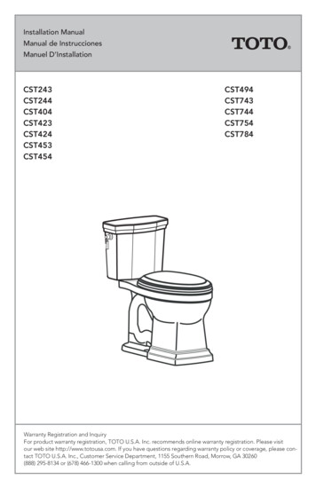
Installation ManualManual de InstruccionesManuel 53CST454CST494CST743CST744CST754CST784Warranty Registration and InquiryFor product warranty registration, TOTO U.S.A. Inc. recommends online warranty registration. Please visitour web site http://www.totousa.com. If you have questions regarding warranty policy or coverage, please contact TOTO U.S.A. Inc., Customer Service Department, 1155 Southern Road, Morrow, GA 30260(888) 295-8134 or (678) 466-1300 when calling from outside of U.S.A.
THANKS FOR CHOOSING TOTO!The mission of TOTO is to provide the world with healthy, hygienic and morecomfortable lifestyles. We design every product with the balance of form and functionas a guiding principle. Congratulations on your choice.COMMON TOOLS NEEDED 10” adjustable wrenchCarpenter’s LevelHacksawTape Measure Hand Pliers Flat Screwdriver Putty KnifeADDITIONAL ITEMS (NOT SUPPLIED BY TOTO): Bowl Wax Ring Closet Flange Mounting Bolts(usually 2 T-bolts, 2 metal washers and 2 nuts) Water Supply Line(typically 1/2” compression to 7/8” ballcock) Toilet Seat (TOTO SoftClose recommended)INCLUDED PARTSCheck to make sure you have all these parts from the package:TankaTank Lidba. Bolts (metal) - 2b. Washers (rubber) -2Tank to Bowl Gasketdcc. Washers (metal) - 4d. Nuts (metal) -43efe. Caps (plastic) - 2f. Base (plastic) - 2ENGLISHTABLE OF CONTENTSThanks for Choosing TOTO ! . 3Before Installation. 3Common Tools Needed . 3Included Parts . 3Before Installation. 4Installation Procedure . 4Maintenance Instructions . 7Care and Cleaning. 9Warranty . 10Rough-In Dimensions . 28Replacement Parts. 29
BEFORE INSTALLATIONRead these instructions thoroughly before beginning work.Please leave instructions for customers. These instruction contain maintenanceand warranty information.If necessary, remove the existing toilet.ENGLISHIMPORTANT!Due to the powerful performance of our Cyclone, G-Max, E-Max and Power Gravityflushing systems, they are not specified for back-to-back installations. The onlymeans of installing these toilets in a back-to-back situation is when the toilet drainconnections incorporate a WYE fitting. Please contact your builder or contractor priorto this installation.Double Combination WYE / 1/8 BendDouble Sanitary Tee / Sanitary CrossYESNOFor your new TOTO toilet to fit correctly, the rough-in, the distance between theFinished Wallfinished wall to the center of thecloset flange, must be at least12 inches for most models.NOTE: Models with 10”C/LSupplyrough-in have model numbersValveending with “.10”, for exampleClosetFlangeC744EF.10."RI"INSTALLATION PROCEDURE1) Clean any debris out of the closet flangeand then install new mounting bolts(not supplied) into the slots of the closetflange (see Illustration 1). The head of thebolt should be inserted into the slot withits threads facing upward.2) Carefully turn the toilet upside downonto some padding. Firmly press a newbowl wax ring (not supplied) onto thecircular recess around the toilet bowl’shorn (see Illustration 2). Turn the toiletupright and gently lower into positionover the closet flange. With toiletproperly aligned, press firmly on bothsides of toilet rim to set the bowl waxring (see Illustration 3).CAUTION: Do not move the bowl afterthe bowl wax ring is set. Thread the nutsand tighten evenly until bowl is snug tocloset flange. Install the bolt caps (seeIllustration 3).CAUTION: Do not over-tighten the nutsas damage to the china bowl may result.4Ill. 1Ill. 2Wax RingHornIll. 3Bolt CapNut *Washer *Base CapBowl Base* Not SuppliedThree Points of Contact
INSTALLATION PROCEDURENOTE: Three Points of Contact:The toilet bowl has three points ocontact, which will actually contact thebottom of the toilet tank when properlyinstalled. The location of these pointscan be seen on the bowl at the tankreceiving area. The three points are frontleft (1), front right (2), and back center(3). Recall these three points during theToilet Tank installation.Points of Contact32ENGLISH1Ill. 4Fill Valve Nut3) Place the tank upside down onto somepadding. Inspect the smaller fill valvenut and larger flush valve nut for asecure connection (see Illustration 4).Try to tighten the nuts with your hands.If loose, tighten the nut hand tight andan additional 1/4 turn for the smaller fillvalve nut and an additional 1/2 turn forthe larger flush valve nut.Place the tank-to-bowl gasket onto theflush valve nut. While pressing down,spread the gasket over the nut until thegasket touches the bottom of the tank.A slight gap between the tank bottomand the gasket is allowable.Flush Valve NutTank to BowlGasketIll. 5Metal WasherRubber Washer4) Lay the tank down on its back. Place arubber washer onto a brass bolt (seeIllustration 5). Reach inside the tankand position the bolt through one ofthe holes in the bottom of the tank.On the outside of the tank, place ametal washer and nut onto the bolt.Hold the bolt centered in the hole andtighten the nut finger tight. Turn the nutan additional 1/2 turn with a wrench.Repeat this process for the remaininghole in the tank.Pick up the tank and carefully guidethe brass bolts to align the tank withthe bowl. Attach a metal washer andnut to each bolt. Tighten the nuts fingertight and inspect that the tank is level(see Illustration 6). Once level, tightenthe bolts equally until the tank makesTHREE POINTS OF CONTACT with thebowl.NutBoltCut Away ViewIll. 6YES31&2NONO3 Gap1&2Gap1&235
INSTALLATION PROCEDUREENGLISH5) Flush the water supply line for a few secondsto remove any debris that may enter thenew fill valve. (For new home constructionsand/or additions, flush the water supply linefor more than a minute to help remove anyresidual PVC adhesives, solder flux, and/ orpipe sealants that were used for the newplumbing.) Connect the water supply line tothe fill valve threads as seen at the bottomof toilet tank (see Illustration 7). Tighten thisconnection finger tight.CAUTION: Avoid using a wrench to tightenthe connection as you may damage theplastic threads and/or cause the fill valve torotate inside the tank.NOTE: The water supply pressure should be20 to 80 psi static.Ill. 77/8” Ballcock ThreadHAND TIGHTEN ONLYIll. 8SeatHingeCapPlasticBoltSeatStopper6) No ballcock / fill valve adjustments areneeded. The water will automatically stop atproper level. Flush the toilet several times.Check flapper valve for proper operation.Make sure that chain is not tangled and thatthe flapper arm is in its proper position.BowlPlastic Nut7) Install the toilet tank lid onto the toilet tanktop.8) Install the toilet seat onto the toilet bowlusing the mounting hardware in the toiletseat box. Place seat onto bowl and rotatethe hinge down. Position seat stoppersunder the seat hinge. Insert bolt into seathinge and through the toilet bowl. Installplastic nut onto bolt from underneath.Tighten the bolt securely. Install the seatbolt caps.NOTE: Tighten the seat bolt until the hinge issecure. The seat and lid will have slight sideto side movement, which is normal. Thisfreedom of movement allows the seat toSoftClose without binding.6MOUNTING HARDWARE1234561 - Cap2 - Plastic Bolt3 - Seat Hinge4 - Seat Stopper5 - Toilet Bowl6 - Plastic Nut
MAINTENTANCE INSTRUCTIONS1)2)3)4)5)6)Shut off the water supply to the toilet.Flush toilet and remove remaining water from tank with a sponge.Remove the water supply connection at the fill valve.Remove old fill valve and use damp sponge to clean hole in tank.Place new fill valve inside tank hole.Thread mounting nut onto fill valve shank and tighten the nut.NOTE: Do not over-tighten. Be sure to install fill valve in a position that does notinterfere with the trip lever operation.7) Connect water supply to fill valve shank and hand-tighten only.NOTE: Do not overtighten. These are plastic parts. Never use pipe dope on anywater supply connection.8) Attach refill tube to fill valve nipple and clip other end of refill tube to the overflowpipe.9) Turn water supply ON and check for leaks outside the tank.NOTE: As water fills the tank, water is also directed into the overflow tube via therefill tube. This additional flow of water is critical to refilling your toilet’s bowl.Once the water stops filling the tank, some residual drops of water may dripfrom the fill valve. This is NORMAL as these drops will subside.Water Level AdjustmentDepending on the manufacturing plant, you may have one of two of the following fillvalves:Type AType CType BWater LevelFor Type A and C Fill Valve:Refer to the water level (WL) setting markedon the inner wall of the tank. Allow the water to fill the tank. Turn the adjustment screwclockwise in the ( ) direction to increase thewater level height (see Illustration 1). Turnthe adjustment screw counter-clockwise inthe (-) direction to decrease the water levelheight. Flush the toilet to verify the correctwater level. Adjust as necessary.For Type B Fill Valve:There are no water level adjustments. Thefill valve has been preset at the factory.7Ill. 1WaterLevelTop ofOverflowTubeENGLISHFill Valve Installation Procedure
MAINTENANCE INSTRUCTIONSReplacing the Flush Valve(ST453U and ST403U Model Tanks)1)ENGLISHTurn off water supply and flush the toilet.Remove the remaining water from tankwith a sponge.2) Remove the tank lid and place it upsidedown on a clean surface.3) Pull the clip on top of trip leaver gear boxas shown.4) Pull gear box away and set on the side asshown. (see ill. 1 & ill. 2)5) Rotate and pull up on the flush tower toremove it. (see ill. 3)6) Remove the grey rubber seal gasket andrinse under running water to clean. (see.ill. 4)7) Place the gasket back on the flush tower.8) Align and place the flush tower into housing and gently press to snap and to lockinto place.9) Replace the trip lever gear box and pushdown on lever to lock it in place.10) Carefully install the tank lid back on thetank.11) Flush the toilet several times making surethe trip lever operates normally.12) Check the water level in the tank andinspect for signs of any leakage.Ill. 2Ill. 1Ill. 4Ill. 38
MAINTENANCE INSTRUCTIONSReplacing the Drain ValveRefill TubeENGLISH1) Shut off the water supply.ill. 12) Flush the toilet to remove the water inside thetank.3) Remove the tank lid and place somewhere safe.NOTE: Before removing anything from the tank,note the placement of the drain valve, chain andrefill tube.4) Unhook the refill tube from the overflow tube ofthe drain valve.Flush Tower5) Unhook the chain from the trip lever.6) Uninstall the tank (refer to the toilet installationmanual).ill. 27) Remove the drain valve body from the tank.8) Replace the drain valve in the same position asthe former drain valve.9) Hand tighten the mounting nut of the drain valveand use a wrench to tighten another 3/4 turn.10) Reinstall the tank onto the bowl and place thechain and refill tube the same way as it was forthe former drain valve.11) Turn the water supply back.12) Check for any leakage after the tank has beenfilled.Drain ValveCARE AND CLEANINGWARNING!DO NOT USE IN-TANK BOWLCLEANERS.The use of high concentration of chlorine or chlorine-related products can seriouslydamage fittings in the tank. This damage can cause leakage and property damage.TOTO shall not be responsible or liable for any tank fitting failure or damage causedby the use of in-tank bowl cleaners.9
WARRANTYENGLISH1. TOTO warrants its vitreous china products (“Product”) to be free from defects in materialsand workmanship during normal use when properly installed and serviced, for a period of one(1) year from date of purchase. This limited warranty is extended only to the ORIGINAL PURCHASER of the Product and is not transferable to any third party, including but not limited toany subsequent purchaser or owner of the Product. This warranty applies only to TOTO Productpurchased and installed in North, Central and South America.2. TOTO’s obligations under this warranty are limited to repair, replacement or other appropriate adjustment, at TOTO’s option, of the Product or parts found to be defective in normaluse, provided that such Product was properly installed, used and serviced in accordance withinstructions. TOTO reserves the right to make such inspections as may be necessary in order todetermine the cause of the defect. TOTO will not charge for labor or parts in connection withwarranty repairs or replacements. TOTO is not responsible for the cost of removal, return and/or reinstallation of the Product.3. This warranty does not apply to the following items:a.Damage or loss sustained in a natural calamity such as fire, earthquake, flood, thunder,electrical storm, etc.b.Damage or loss resulting from any accident, unreasonable use, misuse, abuse, negligence, or improper care, cleaning, or maintenance of the Product.c.Damage or loss resulting from sediments or foreign matter contained in a water system.d.Damage or loss resulting from improper installation or from installation of the Product ina harsh and/or hazardous environment, or improper removal, repair or modification of theProduct. (NOTE: Product model codes allow a maximum of 80 PSI. Check local codes orstandards for requirements).e.Damage or loss resulting from electrical surges or lightning strikes or other acts which arenot the fault of TOTO or which the Product is not specified to tolerate.f.Damage or loss resulting from normal and customary wear and tear, such as gloss reduction, scratching or fading over time due to use, cleaning practices or water or atmosphericconditions.g.Tank flushing mechanisms of plastic or rubber moving parts.h.Toilet seats of plastic, wood or metal.4. In order for this limited warranty to be valid, proof of purchase is required. TOTO encourageswarranty registration upon purchase to create a record of Product ownership at http://www.totousa.com. Product registration is completely voluntary and failure to register will not diminish your limited warranty rights.5. THIS WARRANTY GIVES YOU SPECIFIC LEGAL RIGHTS. YOU MAY HAVE OTHER RIGHTSWHICH VARY FROM STATE TO STATE, PROVINCE TO PROVINCE OR COUNTRY TO COUNTRY.6. To obtain warranty repair service under this warranty, you must take the Product or deliver itprepaid to a TOTO service facility together with proof of purchase (original sales receipt) and aletter stating the problem, or contact a TOTO distributor or products service contractor, or writedirectly to TOTO U.S.A., INC., 1155 Southern Road, Morrow, GA 30260 (678) 466-1300 or (888)295-8134, if outside the U.S.A. If, because of the size of the Product or nature of the defect, theProduct cannot be returned to TOTO, receipt by TOTO of written notice of the defect togetherwith proof of purchase (original sales receipt) shall constitute delivery. In such case, TOTO maychoose to repair the Product at the purchaser’s location or pay to transport the Product to aservice facility.WARNING! TOTO shall not be responsible or liable for any failure of, or damage to, this Product caused by either chloramines in the treatment of public water supply or cleaners containingchlorine (calcium hypochlorite). NOTE: The use of a high concentrate chlorine or chlorine relatedproducts can seriously damage the fittings. This damage can cause leakage and serious propertydamage.THIS WRITTEN WARRANTY IS THE ONLY WARRANTY MADE BY TOTO. REPAIR, REPLACEMENTOR OTHER APPROPRIATE ADJUSTMENT AS PROVIDED UNDER THIS WARRANTY SHALL BETHE EXCLUSIVE REMEDY AVAILABLE TO THE ORIGINAL PURCHASER. TOTO SHALL NOT BERESPONSIBLE FOR LOSS OF THE PRODUCT OR FOR OTHER INCIDENTAL, SPECIAL OR CONSEQUENTIAL DAMAGES OR EXPENSES INCURRED BY THE ORIGINAL PURCHASER, OR FORLABOR OR OTHER COSTS DUE TO INSTALLATION OR REMOVAL, OR COSTS OF REPAIRS BYOTHERS, OR FOR ANY OTHER EXPENSE NOT SPECIFICALLY STATED ABOVE. IN NO EVENTWILL TOTO’S RESPONSIBILITY EXCEED THE PURCHASE PRICE OF THE PRODUCT. EXCEPT TOTHE EXTENT PROHIBITED BY APPLICABLE LAW, ANY IMPLIED WARRANTIES, INCLUDING THATOF MERCHANTABILITY OR FITNESS FOR USE OR FOR A PARTICULAR PURPOSE, ARE EXPRESSLY DISCLAIMED. SOME STATES DO NOT ALLOW LIMITATIONS ON HOW LONG AN IMPLIEDWARRANTY LASTS, OR THE EXCLUSION OR LIMITATION OF INCIDENTAL OR CONSEQUENTIAL DAMAGES, SO THE ABOVE LIMITATION AND EXCLUSION MAY NOT APPLY TO YOU.10
ÍNDICE¡GRACIAS POR ELEGIR TOTO!La misión de TOTO es dar al mundo estilos de vida más saludables, higiénicos ycómodos. Diseñamos cada producto guiándonos por el principio del equilibrio entreforma y función. Felicitaciones por su elección. HERRAMIENTAS QUE NECESITALlave Ajustable de 10 Pulgadas Pinzas ManualesNivel de Carpintero Destornillador de Cabeza PlanaSierra Para Metales EspátulaCinta Para MedirMATERIALES ADICIONALES (NO SUMINISTRADOS POR TOTO): Sello/Anillo de CeraPernos de Montaje pra la Brida del Suel(Generalmente 2 pernos en T, 2 rondanas, y 2 tuercas)Línea Abastecedora de Agua(Generalmente compresión de 1/2” hasta flotador de 7/8”)Silla del inodoro (Se recomienta silla TOTO SoftClose)INCLUÍA PARTESAsegúrese de que tiene todas las piezas del empaque:Tapa del TanqueTanqueaba. Pernos (metálicos) - 2b. Rondanas (goma) - 2cdc. Rondanas (metálicos) - 4d. Tuercas (metálicas) - 411EmpaquetaduraTanque - Recipienteefe. Caps (plastic) - 2f. Base (plastic) - 2ESPAÑOL¡Gracias por elegir TOTO !. 11Antes de la instalación . 11Herramientas necesarias común . 11Incluía partes . 11Antes de la instalación . 12Procedimiento de instalación . 12Instrucciones de mantenimiento . 15Cuidado y limpieza . 17Garantía . 18Bosquejo . 28Refacciones . 29
ANTES DE LA INSTALACIÓNLea estas instrucciones detenidamente antes de comenzar a trabajar.Proporcione las instrucciones a los clientes. Estas instrucciones contieneninformación sobre el mantenimiento y la garantía.Si es necesario, quite el inodoro existente.¡IMPORTANTE!Debido a la potente rendimiento de nuestro Ciclón, G-Max, S-Max y la gravedad dealimentación de agua corriente, no se precisan para las instalaciones de “back-toback”. La única forma de instalar estos baños en una situación de “back-to-back“escuando las conexiones del desagüe WC incorporar un accesorio estrella. Por favor,póngase en contacto con su constructor o contratista antes de esta instalación.ESPAÑOLDoble Combinación WYE / 1/8 CurvaDoble Sanitarias T / Sanitarias CruzSÍNOCon el fín que su nuevo inodoroParedTOTO se adapte correctamente,la fontanería gruesala, distanciaVálvula dedesde la pared hasta el centro de laSuministrobrida del suelo, debe ser al menos12 pulgadas para la mayoría de los"RI"modelos. Modelos con gruesalafontanería 10 pulgadas tienennúmeros de modelo que terminan en “0.10”, por ejemplo C744EF.10.C/LBrida delSueloPROCEDIMIENTO DE INSTALACIÓN1) Limpie la suciedad de la brida del suelo, luego instale losnuevos pernos de montaje (no suministrados) en las ranurasde la brida del suelo (ver Ilustración 1). La cabeza delperno debe insertarse en la ranura con el vástago roscadoapuntando hacia arriba.2) Dé vuelta al inodoro con mucho cuidado de modo quequede mirando hacia abajo sobre un acolchonado.Presione firmemente un nuevo anillo de cera de recipiente(no suministrado) sobre el encastre circular alrededor dela apertura de salida (ver Ilustración 2). Levante el inodoroen dirección vertical y suavemente bájelo hasta colocarlosobre la brida del suelo. Con el inodoro debidamentealineado, presione firmemente a ambos lados el bordedel inodoro para fijar el anillo de ceradelrecipiente (ver Ilustración 3).Ill. 3PRECAUCIÓN: No mueva el recipien te unavez haya fijado el anillo de cera. Enrosque lastuercas y aprietélas igualmente hasta que elinodoro quede ajsutado a la brida del suelo.Instale las tapas de los pernos. (ver Ilustración3). No apriete demasiado las tuercas a losdaños a la taza porcelana.12TapaTuerca *Rondana *Base dela TapaBase delRecipiente* No SuministradosIll. 1Ill. 2Anillo deCeraHornTres Puntos de Contacto
PROCEDIMIENTO DE INSTALACIÓNNOTA: Tres untos de Contacto:El recipiente del inodoro tiene tres puntos decontacto, los cuales deberán tocar la partede abajo del tanque cuando se es instaladodebidamente. La ubicación de estos puntospuede ser vista en la parte del recipientedonde debe ir el tanque. Los tres puntos sondelantero izquierdo (1), delantero derecho(2), y tracero central (3). Recuerde estos trespuntos cuando esté instalando el tanque. en laparte del recipiente donde debe ir el tanque.Los tres puntos son delantero izquierdo (1),delantero derecho (2), y tracero central (3).Recuerde estos tres puntos cuando esteinstalando el tanque.Puntos de Contacto3Ill. 44) Acueste el tanque sobre su parte trasera.Coloque una rondana de goma en el pernometálico (ver Ilustración 5). Extienda su manodentro del tanque y coloque el perno a travésde uno de los orificios del fondo del tanque.En la parte de afuera del tanque, coloque unarondana metálica y una tuerca en el perno.Mantenga el perno centrado en el orificio yapriete la turca con sus dedos. Dé 1/2 vueltaadicional a la tuerca con la llave para tubería.Repita este proceso para el otro orificio deltanque. Levante el tanque y cuidadosamenteguíe los pernos metálicos para alinear eltanque con el recipiente. Fije una rondanametálica y una tuerca a cada perno. Aprietelas tuercas con sus dedos e inspeccioneque el tanque haya quedado nivelado. Unavez nivelado, apriete los pernos igualmentehasta que el tanque haga TRES PUNTOS DECONTACTO con el recipiente.13Tuerca Valvulade VaciadoESPAÑOLTuerca Valvulade Llenado3) Dé vuelta al inodoro de modo que quedemirando hacia abajo sobre algún acolchonado. Inspeccione la tuerca pequeñade la válvula de llenado y la tuerca grandede la válvula de vaciado para garantizar laconexión (ve Ilustración 4). Trate de apretar lasturcas con su mano. Si aún siguen holgadas,apriételas manual mente y dé 1/4 de vueltaadicional a la tuer ca pequeña de la válvula dellenado y 1/2 vuelta a la tuerca grande de laválvula de vaciado.Coloque la empaquetadura del tanquerecipiente sobre la tuerca de la válvula devaciado. Mientras presiona hacia abajo,despliegue la empaquetadura sobre la tuercahasta que esta toque el fondo del tanque. Unpequeño espacio entre el fondo del tanque yla empaquetadura está permitido.21Empaquetaduratanque-recipienteIll. 5RondanaMetalicaRondana deGomaTuercaPernoVista en CorteIll. 6SI31&2NONO3 Espacio1&231&2Espacio
PROCEDIMIENTO DE INSTALACIÓNESPAÑOL5) Descargue la línea de suministro de aguapor algunos segundos para removercualquier suciedad que haya entradoa la nueva vávula de llenado. (Paraconstrucciones nuevas y/o adiciones,descargue la línea de suministro de aguapor más de 1 minuto para ayudar a removercualquier residuo de adhesivo de PVC,soldadura plástica, y/o sellantes de tuberíaque fueron usados para la nueva tubería).Conecte la línea de suministro de agua a larosca de la válvula de llenado como se veen la parte de abajo del tanque del inodoro(ver Ilustración 7). Apriete esta conexi óncon sus dedos.PRECAUCIÓN: Evite usar una llave paratubería al apretar la tubería ya que estopodría dañar las roscas plásticas y/o causarque la válvula de llenado rote dentro deltanque.Ill. 77/8” Rosca del FlotadorAPRETAR SOLAMENTEVUELTO MANUALMENTEIll. 8Bisagra dela SillaTapaPemoPlasticoPiezas deRestriccionNOTA: La presion de la línea de suministro deagua debe ser de 20 a 80 psi estática.Recipiente6) No es necesario ajustar la válvula derelleno/ llave del flotador. El agua se tendráal nivel apropiado de forma automática.Tire la cadena varias veces. Controleque la válvula de la cisterna funcioneadecuadamente. Asegúrese de que lacadena no esté enredada y que el brazode la cisterna se encuentre en la posicióncorrecta.Tuerca Platica7) Instale la tapa del tanque en el inodoro.HERRAJES DE MONTAJE8) Instale el asiento del inodoro sobre elrecipente, usando los herrajes de montajede la caja del asiento del inodoro (verIlustración 8).Coloque la silla sobre elrecipiente y rote la bisagra hacia abajo.Posicione las piezas de restricci ón dela silla debajo de las bisagras de la silla.Introduzca el perno dentro de la bisagra dela silla y a través del recipiente del inodoro.Instale la tuerca plástica en el perno desdela parte de abajo. Apriete los pernos asegurándolos. Instale las tapas.1NOTA: Apriete los pernos de la silla hastaque la bisagra est é asegurada. La sillay la tapa tendr án pequeños movimientos de lado a lado, esto es normal. Estalibertad de movimiento permite que la sillaSoftClose cierre sin que se golpee.14234561 - Tapa2 - Perno Plasticot3 - Bisagra de la Silla4 - Seat Stopper5 - Recipiente6 - Tuerca Plastia
INSTRUCCIONES DE MANTENIMIENTOProcedimento de reemplazoCierre el suministro de agua al excusado.Tire la cadena y retire el agua restante del tanque con una esponja.Quite la conexión del suministro de agua de la válvula de llenado.Quite la válvula de llenado anterior y utilice la esponja húmeda para limpiar el orificiodel tanque.5) Coloque la válvula de llenado nueva en el orificio del tanque.6) Enrosque la tuerca de montaje en el vástago de la válvula de llnado y ajuste la tuerca.NOTA: No ajuste demasiado. Asegúrese de instalar la válvula de llenado en unaposición que no interfiera con el funcionamiento de la palanca de descarga.7) Conecte el suministro de agua al vástago de la válvula de llenado y sólo ajústelomanualmente.NOTA: No ajuste demasiado. Éstas son piezas plásticas. No utilice lubricante en ninguna conexión de suministro de agua.8) Conecte el tubo de relleno al niple de la válvula y sujete el otro extremo del tubo derelleno al tubo de desagüe.9) Abra el suministro de agua y verifique que no haya pérdida de agua fuera del tanque.NOTA: A medida que el agua llene el tanque, también será derivada al tubo dedesagüe a travs del tubo de relleno. Este flujo de agua adicional es fundamentalpara rellenar el recipiente del excusado. Una vez que el tanque está lleno y elsuministro de agua se interrumpe, es probable que caigan algunas gotas de aguaresidual de la válvula de llenado. Esto es NORMAL y las gotas dejarán de caer.Ajuste del nivel del aguaDependiendo de la planta de fabricación, usted debe tener una o ambas de lassiguientes válvulas de llenado: Tipo ATipo BTipo CLinéa deAguaPara una Válvula de Llenado Tipo A y C:Refere a la marca para el nivel de agua(WL) en la pared interior del tanque.Permita que el agua llene el tanque. Gireel tornillo de ajuste en el sentido de lasagujas del reloj en la dirección ( ) paraaumentar la altura del nivel del agua. (verIlustración 1). Gire el tornillo en sentidocontrario a las agujas del reloj en la dirección (-) para disminuir la altura del niveldel agua. Tire la cadena para verificar elnivel correcto del ajuste si es necesario.Para la Válvula Tipo B:No hay ajustes de niveles de agua. Laválvula de llanado nado se ha predeterminado de fábrica.15Ill. 1Parte Superior del Tubo deRebosadero/Tubo de RellenoWLESPAÑOL1)2)3)4)
INSTRUCCIONES DE MANTENIMIENTORemplacement de válvula de llenado(Tanque del modelo ST453U y ST403U)1. Cierre el suministro de agua y descargue el inodoro.2. Quite la tapa del tanque y déjela invertida sobre unaAÑOLESPAÑOL3. Levante la traba ubicada en la parte superior de la cajade cambios de la palanca de descarga como se muestra.4. Retire la caja de cambios y deje a un lado como semuestra. (ver Ill. 1 y Ill. 2)5. Rote y tire hacia arriba la torre de descarga para quitarla.(ver Ill.3)6. Quite la junta de sello de goma gris y enjuáguela bajo elchorro de agua corriente para limpiarla. (ver Ill.4)7. Coloque la junta nuevamente sobre la torre de descarga.8. Alinee y coloque la torre de descarga sobre la base ypresiónela suavemente para que entre y se asegure en sulugar.9. Vuelva a colocar la caja de cambios de la palanca dedescarga y presione la traba para que la caja quedease
proper level. Flush the toilet several times. Check flapper valve for proper operation. Make sure that chain is not tangled and that the flapper arm is in its proper position. 7) Install the toilet tank lid onto the toilet tank top. 8) Install the toilet seat onto the toilet bowl using the mounting hardware in the toilet seat box.