Transcription
Daylight SensorDesign and Application Guide
Daylight Sensor Design and Application GuideVocabularyDaylight Harvesting: The term used in the building controls industry for a controlsystem that reduces electric light in building interiors when daylight is available, inorder to reduce energy consumption.Daylight Row: A group of fixtures adjusted equally based on daylighting readingsDaylight Sensor: A device that reads available light and sends a signal to the controlsystem. Daylight Sensor Photo Cell Photo SensorMultiple Row Daylighting: A form of daylighting in which multiple daylight rows arecontrolled by the same sensor. Each row is calibrated to provide a balanced amountof light throughout the space.Work Surface Light Level: The light level measured in FC using a light meterat the work surface. If cubicle walls are in use then this value is measured at thecubicle height.Desired Light Level: The target work surface light level.Target Setpoint (TSP): The specified electric light level when there is no daylightentering the space. Also known as the Nighttime Target Setpoint.Threshold: A specified light level that is required to turn electric lights ON or OFF.Specified light levels represent the lights levels at which an action will occur in thesystem. This applies to switching/non-dim scenarios.Gain: The numeric value set during calibration that determines how aggressive thedaylighting is. The higher the gain, the more the lights will dim.Fixture Feedback: Light from a fixture shining directly onto a daylight sensor andcausing the system to behave unexpectedly. Based on the Electric Light Contribution(ELC) on the photo sensor from the surrounding fixtures. Sometimes known aselectric light impact.Max Light Level: The method of daylighting through cutting off all zones abovethe daylighting level and leaving other zones unaffected. This cutoff point can bechanged throughout the space using multi‑row daylighting.D Lutron
Table of contents1Dayliglht harvesting3Daylight sensor benefits4Codes and standards4Different daylighting methods8Different types of daylighting11Sensor placement guidelines16Fixture feedback19Special considerations20Wireless daylight sensor21Wired daylight sensorLutron 1
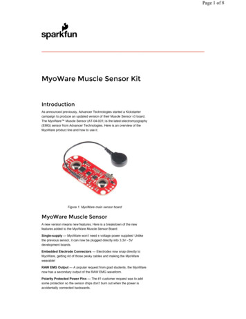
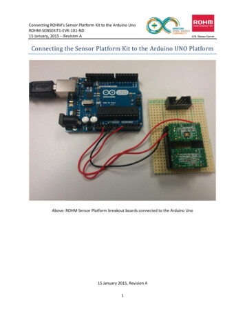
Daylight Sensor Design and Application GuideDaylight harvestingDaylight harvesting, which takes advantage of naturally available light, is a key energy-savingstrategy for commercial spaces. The principle is simple: the electric lights in a space canautomatically be dimmed downed or turned off when enough natural light is entering the space.Annual electricity use in commercial buildings138%403529%302526%20157%1050LightingFull OnDimHVACOtherDaylight Harvesting dims electric lightsor switches them off during the day to takeadvantage of available sunlight.OfficeEquipment20%–60%Light Savings2According to the U.S. Department of Energy, lighting accounts for an average of 38% of electricityusage in commercial buildings, more than any other building system. When seeking a dramaticreduction in electricity costs, one would be well advised to start with the lights. A thoughtfullydeployed daylight harvesting program for building lighting can typically deliver energy savings of20-60%, while providing the assurance that occupants have the right amount of light in the space.1Energy Information Administration, released September 2008. 2003 Commercial Building Energy ConsumptionSurvey (CBECS)2Brambley MR, et al. 2005. Advanced sensors and controls for building applications: Market assessment and potentialR&D pathways. Pacific Northwest National Laboratory: prepared for U.S. Department of Energy.2 Lutron
Daylight sensor benefits Saves energyReduces energy consumption by dimming or turning off electric lights based on the natural daylightentering the space Can deliver up to 60% lighting energy savings in some areas2 Provides comfort and convenienceHelps maintain the proper light level for a space, so a space is never too dark or too bright Continuously adjusts lights automatically so occupants don’t have to manually adjust them as daylightlevels change. Meets codes and standardsMeets the mandatory requirements set for building construction and renovation Can contribute to obtaining points in several LEED credit categoriesLutron 3
Daylight Sensor Design and Application GuideCodes and standards that may applyLEED—up to 19 pointsDaylight sensors can contribute up to 19 possible points in the LEED 2009 NC rating system.ASHRAE 90.1 – 2010 (energy standard for commercial buildings)Parking Garage Lighting Control (9.4.1.3)Transition lighting and lights within certain parameters with relation to natural light must be automaticallyreduced in response to daylighting.Automated Daylighting Controls for Sidelighted Areas (9.4.1.4)The lamps for general lighting must be controlled by at least one multilevel daylight control in any enclosedspace that has more than 250 ft2 of window lit area.Automated Daylighting Controls for Toplighted Areas (9.4.1. 5)The lamps for general lighting must be controlled by at least one multilevel daylight control in any enclosedspace that has more than 900 ft2 of skylight lit area.Exterior Lighting Control (9.4.1.7)Exterior lighting must automatically be turned off when sufficient daylight is available.Title 24 – 2013 Part 6 (California’s energy standard)SECTION 130.1 – Indoor Lighting Controls That Shall Be Installed(d) Automatic daylighting controlsAutomatic daylighting controls must be used to provide multi-level or continuous dimming in spaces withmore than 250 ft2 of daylight area.IECC 2012 (International Energy Conservation Code)Daylight Zone Control (405.2.2.3)Multiple daylight zones must be separately controlled from the general area lighting and can be controlledeither manually or via an automatic daylight sensor.IgCC 2012 (International Green Construction Code)Automatic Daylight Controls (609.5)Automatic daylight controls shall be provided for all daylight zones.These summaries are meant as a general reference of some of the mandatory requirements that daylightsensors help meet. They may or may not apply to your project. Please refer to your local building energycode or authority having jurisdiction for your precise requirements.4 Lutron
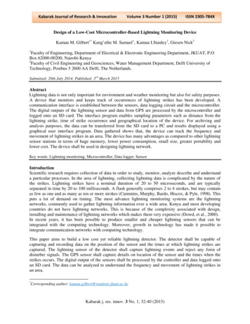
Different daylighting methodsClosed loopClosed loop is an approach to daylighting that attemptsto keep the illumination at the sensor constant. Thisapproach is task oriented; the sensor looks directly intothe space of the light that it controls. Sensors placed inside the space, typically directly abovework surface – dependent on sensor instructionsMeasures light level in a narrow viewing angleAdjusts electric light level up or down to maintain adesired light level on the work surfaceA sample private office closed loop sensor setup.*Affected by both electric light and daylightFor accurate performance the sensor can only controlfixtures that are contributing to the field of view– Generally one sensor per task surface– Customer would have to buy far more sensors to coverthe same area The sensor cannot distinguish between daylightfluctuations and changes of surface reflectanceOpen loopIn this approach to daylighting, the illumination atthe daylight sensor varies. It has a wide field of view;the sensor doesn’t look directly into the space thatcontains the lights that it controls. Measures daylight only Wide field of view Often placed outside the space Does not take into account window treatmentsA sample private office open loop sensor setup.** NOTE: Dotted lines are for visualization purposes onlyLutron 5
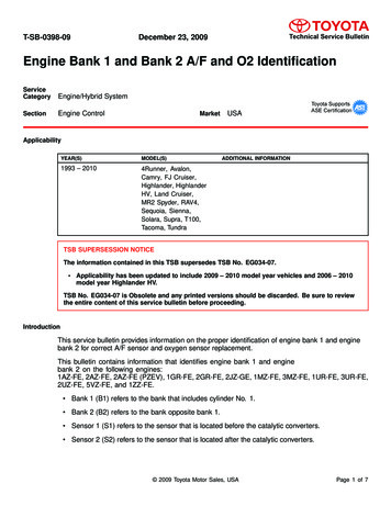
Daylight Sensor Design and Application GuidePartial open loop – Lutron approachIn partial open loop daylighting, sensors arepositioned inside the physical space and take intoaccount the light levels penetrating the area fromnatural light sources, as well as light contributionsfrom the work surface. This approach combinesboth open and closed loop methods. Single sensor can control multiple rowsTakes into account light level actually entering intothe space, accounting for window treatments andnatural weather conditionsNot significantly affected by reflectance from thesurface belowDoes not need to be placed directly above thetask surface* NOTE: Dotted lines are for visualization purposes only6 LutronAn example of a Lutron daylighting system.*
How does partial open loop daylighting work?The two main variables that define the behavior of a system are target setpoint (TSP) and gain. All ofLutron’s systems use TSP and gain to determine how the sensor reading affects the artificial light in aspace. The values are determined during initial set up. Based on which system is being used, one or bothof the variables may then be adjusted to allow additional tuning.Target setpoint (%)This setting determines the ballast light level when the daylight sensor is reading 0FC.Another way to think about it is TSP is the percentage the ballasts will go to at night.The HIGHER the TSP, the HIGHER the electric light output.Gain adjustmentGain determines how much the lights will dim when daylight is present.If you have a high gain, the lights will be more affected by the current daylight sensor readings, so electriclight output will be lower.The HIGHER the gain the LOWER the electric light output.Lutron 7
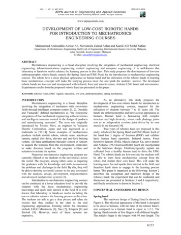
Daylight Sensor Design and Application GuideDifferent types of daylightingSwitched daylightingIn switched daylighting, loads are turned off when the daylight meets a minimum desired level. This type ofdaylighting uses a delay-to-off and hysteresis in order to prevent frequent on-off behavior.In the chart below, the electric lights have been designed to supply the desired amount of light at deskheight. You can see as the sun rises the total light in the space increases. Once the daylight entering thespace is enough to exceed the minimum required light level (with a built-in hysteresis), the electric lightswill turn off. The electric lights will then remain off until the point in the day at which the natural light can nolonger provide the minimum required light level in the space.One of the downsides of switched daylighting is that the space is over lit just before there’s enough daylightthe space to provide the minimum required light level.8 Lutron
Bi-level daylightingBi-level daylighting is very similar to switched daylighting, but with the addition of a 50% light level. Electriclighting to the left will move from 100% to 50% to off as the daylight becomes more abundant. In the chartbelow, you can see how the electric light contribution in the space is additive to the daylight entering thespace. As the total light in the space increases, the electric lights will dim to 50%. They’ll turn off oncethe daylight entering the space is enough to provide the minimum required light level for the space. Thebi-level, or 50% level, helps avoid having the space be over lit before there’s enough daylight to provide theminimum required amount of light.Lutron 9
Daylight Sensor Design and Application GuideContinuous daylightingContinuous daylighting involves smooth, continuous dimming from low end to high end in order to maintainthe desired light level. Continuous daylighting adjusts lights based on the amount of daylight that’s always inthe space, ensuring that the minimum light level is achieved without over-lighting the space (as in switchedand bi-level daylighting).10 Lutron
Sensor placement guidelinesGeneral placement guidelines Place the daylight sensor so its arrow is pointed at the nearest window at a distance from the window ofone to two times the effective window height (H).The effective window height (H) starts at the window sill or 3 ft (1 m) up from the floor, whichever is higher,and ends at the top of the window. Ensure that the view of the daylight sensor is not obstructed (e.g. ceiling fans or pendant fixtures). Allocate one sensor for each partitioned space such as a private office. In case of an open office allocate one sensor at least every 30 linear feet of window wall. One sensor for every individually controlled shade group will provide the ideal daylighting behavior.(See “Multiple Shades” on page 12 for more information.)Proper sensor placement should try to maximize the ratio of natural light to artificial light, while not beingconstantly washed out with sunlight.Avoid placing the sensor in direct light from fixtures in the space. This can cause the sensor’s readings tobe off and the system to not daylight properly.Corner officeIf working with a small corner office point thesensor toward either window opening.If working with a large corner space either use: Two sensors, one pointed toward each façade.A single sensor close to the corner, pointed ateither façadeNOTE: Graphics are not drawn to scale.Lutron 11
Daylight Sensor Design and Application GuideNarrow private office or hallwayIn this application, you won’t have a good locationfor the sensor that’s 1 to 2 window heights awayfrom the window. If you place the sensor closerthan 1 window height, the sensor will receive toomuch sunlight and won’t be able to operate theelectric lights with precision.Try placing the sensor against the window, facingin toward the space.Multiple shades/open officeInconsistent shade (manual or electric) positionswill affect the amount of light coming into thespace from one section of the office to another.One sensor isn’t enough for the space becausethe lights/shades will only respond to the sensorthat is receiving the natural light, leaving part of thespace under lit.Adding another sensor ensures that the entirespace will be properly lit.NOTE: Graphics are not drawn to scale.12 Lutron
SkylightsHigh windows, slanted ceilingMount the sensor as close as possible to theskylight with the field of view oriented toward thefloor under the skylight opening.The guidelines for high slanted ceilingsare dependent on the rest of the space.For jobs with this setup please contactthe System Sales Engineering Team(systemsalesengineers@lutron.com).Do not position the sensor inside skylight.NOTE: Graphics are not drawn to scale.Lutron 13
Daylight Sensor Design and Application GuideSteep slanted ceilings/narrow office spaceWhen dealing with steeply slanted ceilings in anarrow office space place the sensor on the slantand point it away from the window.In an office like this natural light will wash outthe sensor for most of the day. This may affectthe accuracy of our daylighting system. WeNOTE: Graphics are not drawn to scale.14 Lutronrecommend you contact Lutron in order to tweakthe sensor settings.If the ceiling has a flat section parallel to the floor,place the sensor on the flat, rather than thesteep, section.
High ceilingsHard shadowsYou can place a daylight sensor on a high ceilingas long as the sensor can still read a workablelight level. (Keep in mind that a sensor on a highceiling might lose some accuracy.)Avoid hard shadows on the sensor caused byaspects of the interior design such as columns.If you place a sensor where it doesn’t receiveany reflected light and it’s in the dark, itwon’t work.NOTE: Graphics are not drawn to scale.Lutron 15
Daylight Sensor Design and Application GuideFixture feedbackFixture feedback refers to direct light from the fixtures in the daylighting area contributing to the light at thedaylight sensor. High levels of fixture feedback can result in unexpected behavior including light oscillationor under-lit areas. To minimize fixture feedback, position sensors in such a way so they don’t receivedirect light from the fixture.How to measure fixture feedback: Place a light meter on the ceiling in the same location as the daylight sensor. Face the lens of the light meter toward the window, perpendicular to the ceiling Adjust lights to high end; record light meter reading. Adjust lights to off; record light meter reading. Calculate fixture feedback lights on – lights off The fixture feedback should be 5fc or less.Tip! If you know there is fixture feedback, but you can’t move the sensors, try manually decreasing gainto avoid problems. If the fixture feedback is a significant percentage of the overall sensor readings, pleasecall Lutron tech support for assistance.NOTE: Graphics are not drawn to scale.16 Lutron
Possible alternative location with indirect fixturesOption 1: If the fixture is parallel to the window,you can place the sensor on the bottom of thependant pointed toward the window.Option 3: You can also place the sensor in thesame vertical plane as the pendant. This approachmay work for pendant fixtures perpendicular to thewindow, depending on the fixture design.Please see App Note 426 for more information.How to place the sensor on a pendantfixture using Option 3.Option 2: If the fixture is perpendicular but oneside is far enough from the window (see page 11)you can place the sensor as shown below.Ideal placement while using Option 3.NOTE: Graphics are not drawn to scale.Lutron 17
Daylight Sensor Design and Application GuideAvoiding fixture feedback with recessed fixturesAvoid placing a sensor directly facing a recessedfixture or down light, especially if the fixture has awide surface area. Instead, try to place the sensorin between fixtures in a row, as shown at right.NOTE: Graphics are not drawn to scale.18 Lutron
Special considerationsNot enough light at the sensorBefore calibrating, ensure at least 25% ofthe desired light level is reaching the sensorduring calibration. Place a light meter on theceiling in the same location as the sensor.Solution: Move the sensor closer to thenatural light source or calibrate the sensorat a different time of day.Sensor washed out with sunlightIf the sensor is in a location where it’swashed out with sunlight, the calibration willmost likely result in a too low gain. Makesure the sensor placement matches thespec. This will most likely result in under litspaces during certain times of the year, orcertain weather conditions.Solution: Move the sensor to adifferent location.Reflective surfacesReflective surfaces can provideunexpected spikes in daylight sensorreadings. This could result in the light levelchanging dramatically without a significantchange of work surface light.Solution: Move the sensor out ofthe reflection’s path.Window treatmentsWindow treatments will greatly affectthe daylight penetration curve in thespace, especially blackout shades.Solution: Remove or open all windowtreatments when placing the sensor.Then replace or close window treatmentsto test daylighting behavior at varyinglight levels.Lutron 19
Daylight Sensor Design and Application GuideWireless daylight sensorFeatures and capacities Wireless daylight sensor has simple calibrationDaylight compensation through Lutron reliablepartial open loop controlDesigned to give a linear response to changesin viewed light levelLight range 0–1600 lx (0-150 fc).Intuitive test mode provides instantsystem verificationMultiple ceiling mount methods available fordifferent ceiling materialsFront accessible test buttons make set up easy.Battery included; 10-year battery life designRoHS compliantFor indoor use only, temperature 32 F-104 F(0 C-40 C)Dimensions and mounting Width: 1.6 in (41 mm)Depth: 0.7 in (17 mm)Mount within 60 ft (18 m) line-of-sight or 30 ft(9.1 m) through walls, of the receiving devicesCommunication Communicates via Lutron’s reliable ClearConnect Radio Frequency (RF) technologyto other Lutron wireless devices20 LutronShown actual sizeModel numbersWireless daylight sensor434 MHzLRF2-DCRB-WH
Wired daylight sensorFeatures and capacities Mounts easily on any ceiling tile or fixtureThreaded mounting stud may be shortened forapplications with limited fixture heightCalibrated for daylight sensitivity through thelighting control system to which it is attachedReceives IR signals and transfers themto a digital ballast, control module, orsensor interfaceThe infrared receiver receives IR programmingsignals from up to 8.2 ft (2.5 m) awayConstructed of flame-retardant material.Meets IEC 801-2. Tested to withstand 15 kVelectrostatic discharge without damageLED indicates programming modeSensor wire insulation is rated to 600 V, suitablefor fixture installationFor indoor use only, temperature 32 F-104 F(0 C-40 C)Light range 0–5,300 lx (0-500 fc).Model numbersWired daylight sensorEC-DIR-WHDimensions and mounting Width: 1.18 in (30 mm)Depth: 0.69 in (17 mm)Stud length: 1.25 in (32 mm)Sensor lead length 4 in (100 mm) minimumbeyond threaded studTotal wire length from sensor to device must notexceed 100 ft (30 m)Threaded stud diameter 3/8 in (9.5 mm)maximumUse 3/8-16 nut (provided) for mountingCommunication Operates via low-voltage (PELV) standardwired communication20-24 VDC, Class 2 (PELV) low-voltage wiringUses one half (1/2) power draw units on theQS link, only if connected to the QS sensormodule (QSM)Lutron 21
Sensor layout and tuning serviceFine tuning sensor performance is best acheived after the space is fully occupied, furniture is in place, andthe HVAC system is balanced to the environment.Lutron offers a sensor layout and tuning service to ensure that our sensors are installed and calibrated toperform as intended.When the Lutron Sensor Layout and Tuning Service is purchased, we’ll inform the installing contractorwhere to place the sensors (both wired and wireless). During system startup, we will providerecommendations to the installing contractor regarding sensor location in accordance with the installationinstructions. We’ll also provide a rough sensor calibration. Once the building is occupied, we’ll return, up totwo times, to perform sensor fine-tuning.To learn more about this service, please call 1.800.523.9466 or email LSCscheduling@lutron.com.For specification information, see Lutron document LSC-SENS-LT, PN 360-1235.Lutron.com/occsensorsLutron Electronics Co., Inc.7200 Suter RoadCoopersburg, PA 18036-1299World Headquarters 1.610.282.3800Technical Support 1.800.523.9466 (Available 24/7)Customer Service 1.888.LUTRON1 (1.888.588.7661) 06/2014 Lutron Electronics Co., Inc. I P/N 368-3587 REV AB Lutron
Daylight Sensor Design and Application Guide. . lighting to the left will move from 100% to 50% to off as the daylight becomes more abundant. In the chart below, you can see how the electric light contribution in the space is additive to the daylight entering the space. As the total light