Transcription
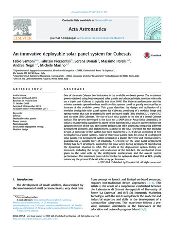
Acta Astronautica 95 (2014) 210–217Contents lists available at ScienceDirectActa Astronauticajournal homepage: www.elsevier.com/locate/actaastroAn innovative deployable solar panel system for CubesatsFabio Santoni a,n, Fabrizio Piergentili b, Serena Donati a, Massimo Perelli c,1,Andrea Negri c,1, Michele Marino c,1aDipartimento di Ingegneria Astronautica, Elettrica ed Energetica – DIAEE, Università di Roma “la Sapienza”,Via Salaria 851, 00138 Rome, ItalyDipartimento di Ingegneria Meccanica e Aerospaziale – DIMA, Università di Roma “la Sapienza”, Via Eudossiana 18, 00184 Rome, ItalycIMT Srl, Via Carlo Bartolomeo Piazza 8, 00161 Rome, Italyba r t i c l e in f oabstractArticle history:Received 28 March 2013Received in revised form31 October 2013Accepted 10 November 2013Available online 19 November 2013One of the main Cubesat bus limitations is the available on-board power. The maximumpower obtained using body mounted solar panels and advanced triple junction solar cellson a triple unit Cubesat is typically less than 10 W. The Cubesat performance and themission scenario opened to these small satellite systems could be greatly enhanced by anincrease of the available power. This paper describes the design and realization of amodular deployable solar panel system for Cubesats, consisting of a modular hinge andspring system that can be potentially used on-board single (1U), double(2U), triple (3U)and six units (6U) Cubesats. The size of each solar panels is the size of a lateral Cubesatsurface. The system developed is the basis for a SADA (Solar Array Drive Assembly), inwhich a maneuvering capability is added to the deployed solar array in order to follow theapparent motion of the sun. The system design trade-off is discussed, comparing differentdeployment concepts and architectures, leading to the final selection for the modulardesign. A prototype of the system has been realized for a 3U Cubesat, consisting of twodeployable solar panel systems, made of three solar panels each, for a total of six deployedsolar panels. The deployment system is based on a plastic fiber wire and thermal cutters,guaranteeing a suitable level of reliability. A test-bed for the solar panel deploymenttesting has been developed, supporting the solar array during deployment reproducingthe dynamical situation in orbit. The results of the deployment system testing arediscussed, including the design and realization of the test-bed, the mechanical stressgiven to the solar cells by the deployment accelerations and the overall systemperformance. The maximum power delivered by the system is about 50.4 W BOL, greatlyenhancing the present Cubesat solar array performance.& 2013 IAA. Published by Elsevier Ltd. All rights reserved.Keywords:CubesatDeployalbe solar panelsPower systemNanospacecraftSolar panel deployment testingModular design1. IntroductionThe development of small satellites, characterized bythe involvement of small personnel teams, very short timenCorresponding author.E-mail addresses: fabio.santoni@uniroma1.it (F. Santoni),fabrizio.piergentili@uniroma1.it (F. Piergentili),sere.dona@gmail.com (S. Donati), massimo.perelli@imtsrl.it (M. Perelli),andrea.negri@imtsrl.it (A. Negri), michele.marino@imtsrl.it (M. Marino).1http://www.imtsrl.itfrom concept to launch and limited on-board resources,requires non-traditional design approaches [1–4]. Thisarticle is the result of a cooperation established betweenthe Laboratorio di Sistemi Aerospaziali of University ofRome “La Sapienza” and IMT Srl, Ingegneria MarketingTecnologia, with the aim to complement the academic andindustrial expertise and skills in the development of ananosatellite subsystem. This experience follows a previous initiative undertaken in the framework of theeducation and outreach program Edusat [5,6].0094-5765/ - see front matter & 2013 IAA. Published by Elsevier Ltd. All rights 3.11.011
F. Santoni et al. / Acta Astronautica 95 (2014) 210–217The diffusion of the Cubesat nanosatellite standard bus,described in [7], has made access to space affordable bylowering the launch cost through the use of specificallydeveloped nanospacecraft dispensers allowing for multiple spacecraft launches [8,9]. This gave impulse to onboard component miniaturization and in particular to thedevelopment of standardized components and innovativemissions [10–13].The Cubesats capabilities could be greatly enhanced byincreasing the available on-board power, while maintaining the compactness and volume limitations imposedby the standard. Technologies and methods for efficientpower generation and storage on-board micro and nanospacecraft have been sought, including the possibility ofusing commercial solar panels in space [14–17], commercial Li-ion batteries [18,19] and ways to maximize solararray power output by efficient interfacing with the loadand batteries [20]. Concerning Cubesat power systems, theavailable surface for body mounted solar panels is so lowthat there are no alternatives to using high efficiency triplejunction solar cells. In this case, the typical maximumdelivered power is in the order of 10 W for triple Cubesats.The main advantage of body mounted solar panels is thatno particular attitude pointing is required. However, themost performing Cubesats developed recently, includingthe 1U, 2 U and 3U size, can take advantage of currentstate of the art miniaturized attitude control systems [21],guaranteeing accurate pointing and maneuvering capabilities, as required by typical high performance and powerdemanding, missions.Deployable solar arrays have been developed for microand nano-spacecraft in order to improve the on-boardpower generation capability (e.g. [17,22]). Some havebeen tested in orbit and are commercially available asa standard “building block” for newly developed Cubesatsystems. These systems are based on many differentdeployment geometries and mechanisms and some havebeen developed having in mind particular satellite orbitaland attitude stabilization scenarios. The simplest systemsare based on single deployable solar arrays, connected tothe main satellite body by one single hinge (e.g. [17]). Inmore complex configurations, the system is based on anumber of interconnected solar panels [22–26].A performance parameter expressing the solar arraycapabilities that can be used in general, not being relatedto a particular mission geometry, is the maximum delivered power, when the sun is orthogonal to the solar arrayin free space (AM0). The increase of on-board powergenerated by deployable solar panel with respect to bodyfixed ones is significant. Several deployable solar panelsolutions for 3U Cubesat have been developed, with totaldelivered power ranging from 22 W to 56 W (e.g. [22–26]),increasing the performance with respect to body mountedsolar panels from 160% to 400% [27].A broad classification of these systems can be performed based on the deployment geometry and solarpanel's orientation once deployed. Three categories havebeen determined based on this classification: (i) thedeployment involves single solar panels, which are connected to the satellite body by one single hinge; (ii) thedeployment involves a number of solar panels connected211in a chain and one solar panel is connected to the satellitebody by one single hinge, without the possibility ofsteering the solar array once deployed; (iii) the deployment involves one or more solar panels connected in achain and one solar panel is connected to the satellite bodyby a system of two hinges, allowing to rotate the solarpanel system relative to the satellite body once the solarpanel is deployed. The system described in this paper is oftype (ii), but it has been designed as a building block of aSADA (Solar Array Drive Assembly).The deployable solar array system described in thispaper has been dimensioned for the maximum obtainablesolar array power, compatible with the standard Cubesatdimensions and Cubesat dispenser limitations. As far asthe single solar panel size is concerned, the obvious choiceis to make it as large as the Cubesat lateral face. Thenumber of solar panels is limited by the maximum numberof staked solar panels that can fit between the Cubesatstructure and the dispenser in the stowed configurationduring launch. The typical solar cell, wires and hingethickness allow in practice only for three stacked solarpanels in the ISISPOD dispenser [28], or two solar panelsin the P-POD dispenser [8]. A study on the deploymentmechanics of this system can be found in [29].The solar panel performance strongly depends on therelative orientation of the sun and the orbit, as well as onthe attitude motion, as discussed in Section 2. The solarpanel deployment system mechanical and electrical designsare depicted in Section 3 and the prototype realization andtest is dealt with in Section 4.2. Geometrical configurationThe geometrical configuration has been selected basedon orbit and attitude stabilization considerations and onthe deployment sequence reliability and impact on thefuture SADA system and other satellite subsystems.2.1. Attitude and orbit configurationThe overall solar array performance in orbit dependsstrongly on the history of the angle of the sun directionwith respect to the solar panel normal and on the totaleclipse time. These are strictly related to the particularmission configuration, including orbital dynamics andattitude stabilization. Hence it is not possible to determineone solar array configuration which is optimal for allmissions. However design drivers can be indicated bytrade-off analysis referred to the most frequent orbitalconfigurations of past Cubesat missions and to typicalattitude stabilization of high performance Cubesats, basedon the assumption that installing high performance steerable solar array on-board is profitable in particular forthree axis stabilized spacecraft.The first design analysis is devoted to comparing theperformance of fixed and steerable deployed solar panels.The analysis is limited to circular sun-synchronous orbits,in which the relative motion of the sun with respect to theorbital plane can be described by one single parameter, thelocal time of ascending node (LT). We also assume the
212F. Santoni et al. / Acta Astronautica 95 (2014) 210–217satellite attitude is nadir pointing, which is the mostcommon among Cubesat missions.2.2. Body-fixed and steerable deployed solar panelsThe solar array performance in terms of average delivered power in one orbit depends on the relative motion ofthe sun with respect to the solar panel normal. The solarpanel orientation of body fixed deployed solar arrays canbe selected in principle in order to maximize the averagepower, including eclipse times.Fig. 1. Sun direction angles in the body fixed reference frame of anominally oriented nadir pointing Cubesat.The solution to this problem for nadir pointing Cubesats includes two limiting cases with a straightforwardsolution. The first one is when the sun is directed along theorbit normal. This situation, in which there is no eclipse isrepresentative of sun synchronous early morning (dawn–dusk) orbits (LT ¼6:00 or LT ¼18:00). In this case theoptimal orientation of the solar panel normal is alongthe orbit normal, so that the solar array is fully illuminatedall the time. The second one is when the sun is in theorbital plane. This situation, in which there is the maximum possible eclipse time at the given altitude, isrepresentative of sun synchronous noon/midnight orbits(LT ¼0:00 or LT ¼12:00). In this case the optimal configuration is having the solar panel normal directed upwardsalong the local vertical. Although the configuration isoptimal for the given orbital and attitude geometry, thegenerated power is much less than the previous case,because the solar panel is illuminated only half orbit andbecause of the sun angle effect along the orbit.In general, the sun moves along a cone in the bodyreference frame, whose aperture can be considered constant in one orbit, as shown in Fig. 2, with non-negligibleseasonal variations due to the inclination of the eclipticwith respect to the Earth's polar axis. In these generalcases, the optimal solar array orientation, taking intoaccount eclipse times, can be obtained only numerically[30,31].The solar array performance could be enhanced,depending on the orbital geometry, if the solar panelswere allowed to rotate about a body-fixed axis.Fig. 2. Motion of the sun in the satellite greference frame for nadir pointin Cubesat, in a sun-synchronous orbit.
F. Santoni et al. / Acta Astronautica 95 (2014) 210–217A comparison of the power generated by body-fixedand steerable deployed solar arrays in terms of percentageof solar power increase of steerable solar panels withrespect to body-fixed is shown in Fig. 3, as a function ofascending node local time. It is assumed that no yawmaneuvers are performed, maintaining exactly the attitude geometry indicated in Fig. 1. The comparison is basedon the average total power over one year. As expected, themaximum improvement is obtained with steerable solarpanels, as high as 134%, is obtained in noon/midnightorbits, in which the attitude motion does not allow tomaintain the solar arrays exposed to the maximum sunillumination. On the contrary, in dawn/dusk orbits norelevant improvements (2%) are observed.This result indicates that in some situations, the average solar array performance can be more than doubled byusing a steerable solar panel system.2.3. Deployed solar panel configurationThe solar array size is mainly determined by geometrical constraints and Cubesat dimensions, not leavingsignificant design margins for the single panel configuration. Hence, the main design trade-off are in the overallsolar panel system geometrical configuration and deployment architecture. The two selected configurations fordesign trade-off are shown in Fig. 4. In the longitudinaldeployment configuration the solar panels are connected213on the side parallel to the main hinge (the one connectingthe solar panel system to the satellite main structure). Inthe lateral deployment configuration the solar panels areconnected on the side perpendicular to the main hinge.The longitudinal configuration has been selected basedon superior performance with respect to the lateral,concerning the following system aspects: Less disturbance torque during deployment, because ofsymmetry. Less moment of inertia of the deployed solar panel about the steering axis (SADA motor size and continuous operation power).Less disturbance on the satellite attitude due to SADAoperation and solar panel motion.No possibility of solar panel impacts on the structure, incase of malfunctioning during the deployment phase.Larger space for installation of secondary hinges, considering that standard triple junction solar cells coverthe solar panel almost completely widthwise.Scalability to 1U and 2U Cubesats.The main drawback associated with the longitudinalconfiguration is the larger increase in the overall satellitemoment of inertia, which might negatively affect attitudemaneuvers.2.4. Deployment sequenceThe deployable solar panel consists of three solarpanels, stacked on each other in the stowed configuration.The deployment sequence develops in two steps, as shownin Fig. 5. First the solar array pack deploys from theCubesat body, when the thermal cut TC1 is activated. Thenthe pack opens, when the thermal cut TC2 is activated,releasing the solar panels in the final configuration.The main hinge, connecting the solar panels assemblyto the satellite structure (red in Fig. 5) must allow (andlimit ) the rotation of the whole assembly by 901, from thestowed to the first step of the deployment sequence. Thesecondary hinges, connecting the solar panels each other(green in Fig. 6) must allow (and limit) the rotation of thesolar panels by 1801.Fig. 3. Comparison of performance of body-fixed and steerable deployedsolar panels for nadir pointing Cubesats in sun-synchronous orbits.Fig. 4. Deployed solar panels' geometrical configuration.Fig. 5. The two phases of the deployment sequence.
214F. Santoni et al. / Acta Astronautica 95 (2014) 210–217The solar panel assembly during and after deploymentis shown in Fig. 6.3. Deployable solar panel design3.1. RequirementsFig. 8. Main hinge assembly (back view).The deployable solar panel system has been designedbased on the overall geometrical configuration selectedabove and taking into account of the main system requirements imposed by the Cubesat structure, Cubesat dispenser, commercial advanced triple junction solar cell size andthickness, mechanical and electrical interfaces. No requirements have been fixed a-priori concerning the systemmass. The goal is to have the system as light as possible,compatible with the other requirements.An additional requirement is that the system should beinstalled externally from standard Cubesat structure without modifications.Taking the system geometrical constraints and thetypical high performance triple junctions solar cells dimensions into account [32], a string of seven solar cells fits ineach solar panel. According to [32], the maximum powerdelivered by one solar cell at AM0, room temperature of28 1C, is about 1.2 W. Hence the solar array system iscapable of delivering about 50 W in the same environmental operative conditions.Fig. 9. Main hinge and solar array assembly (stowed).Fig. 6. Solar panel assembly during and after deployment.Fig. 10. Main hinge and solar array assembly (deployed).Fig. 7. Main hinge assembly (front view).Fig. 11. Secondary hinge assembly.
F. Santoni et al. / Acta Astronautica 95 (2014) 210–2173.2. Mechanical designThe system mechanical design has been focused mainlyon the hinges connecting the solar panels and on thedimensioning of the springs for deployment.The selected material for the solar panels is standardelectronic board FR4, which has been preferred to aluminumFig. 12. Secondary hinge mounted on the solar panels in stowedconfiguration.215because of its thermal stability, flexibility in the electricalinterface design, realization and solar cell integration.The main hinge has been designed to connect the solarpanel assembly to the SADA shaft in one single connectionpoint. The hinge supports two torsion springs, as shown inFigs. 7 and 8 The solar panel is connected to the mainhinge by four screws, as shown in Figs. 9 and 10. Here theSADA shaft connected to the main hinge is also shown.The secondary hinge assembly, based on the sameprinciple, is shown in Fig. 11. This hinge has a stop hingefunctionality, allowing for a rotation of 1801. The stopfunction is provided by the hinge support shape, as shownin Fig. 12 in the stowed configuration. The hinge supportconnected to the upper panel has two small protrudingelements, which limit the rotation of the lower panel inthe correct open configuration. The lower solar panel FR4plate gets direct contact with the stop elements made ofaluminum. The deployment spring energy was calibratedfor a sufficiently soft deployment, as discussed in [29]. As aresult the FR4 plate has the ability to sustain the shockcompletely. The solar panels in the deployed configurationare shown in Fig. 13.3.3. System assemblyThe system assembly consists of two solar panels packs,comprising three solar panels each. The assembly of onepack in the stowed configuration is shown in Fig. 14,including the main external dimensions. These are compatible with the standard Cubesat dispenser ISIPOD [28].The packs installed on the Cubesat structure are shownin Fig. 15. The shaft connecting the two packs is representative of the SADA shaft.4. Prototype integration and testFig. 13. Secondary hinge assembly mounted on the solar panels indeployed configuration.A prototype of the system, assembled as shown inFig. 15, has been realized and used for the deploymentsequence ground testing.Fig. 14. Solar panel pack assembly in stowed configuration. Dimensions in millimeter.
216F. Santoni et al. / Acta Astronautica 95 (2014) 210–217Fig. 17. Low friction support for solar panel deployment testing.Fig. 15. Installation of the solar panel packs on the Cubesat structure inthe stowed configuration.Fig. 18. Low friction lubricated horizontal support, dummy 3U Cubesatstructure, testing equipment and solar panel after deployment.5. ConclusionsFig. 16. Assembled satellite mock-up structure and solar array packs inthe stowed configuration.The prototype includes six solar panels assembled intwo packs made of three solar panels each, as describedabove, and a dummy structure of a 3U Cubesat respectingall of the standard dimensions concerning the externalshape. The assembled prototype ready for testing is shownin Fig. 16.A special equipment set has been developed for thesolar panel deployment sequence testing. The hinges andthe springs are dimensioned for operation in a microgravity environment. Hence a deployment sequence in aregular gravity environment would not be representativeof real conditions in orbit. To release the solar panels'weight from the hinges, a low friction support has beendeveloped, based on small lubricated steel spheres locatedin appropriate spherical holes machined in the support.A steel ball and its support are shown in Fig. 17. Toenhance the low friction motion, a special lubricatedhorizontal table has been employed. The overall view ofthe testing equipment and solar panel after deploymentare shown in Fig. 18.The deployment sequence has been performed severaltimes, with no failures. Only slight changes in the sequence duration have been observed, due to the changinglevel of friction in the low friction support.A deployable solar panel system for Cubesats has beendeveloped in the framework of a cooperation establishedbetween Laboratorio di Sistemi Aerospaziali of Universityod Rome “la Sapienza” and IMTsrl, Ingegneria MarketingTecnologia. The system has been developed for 3U Cubesats, but it is conceived to be scalable to all Cubesat shapefactors, including 6U, 2U and 1U Cubesats, respectingall of the geometrical constraints given by the Cubesatstandard and by the deployment system. The system canbe installed externally from standard Cubesat structures,without modifications. A prototype of the system has beendeveloped, ready to be installed on a SADA (Solar ArrayDrive Assembly). The ground testing of the deploymentsequence has been performed, with no failures or majorproblems.References[1] F. Graziani, F. Santoni, F. Piergentili, F. Bulgarelli, M. Sgubini,S. Bernardini, Manufacturing and launching student-made microsatellites: hands-on education at the University of Roma, in: Proceedings of the 55th International Astronautical Congress (IAC),paper IAC-04-P.5.A.02, Vancouver, Canada, 4–8 October 2004. ISBN:9781604236477.[2] F. Santoni, Risk management for microsatellite design, Acta Astronaut. 54 (3) (2004) 221–228, http://dx.doi.org/10.1016/S0094-5765(02)00291-6.
F. Santoni et al. / Acta Astronautica 95 (2014) 210–217[3] F. Graziani, F. Piergentili, F. Santoni, A space standards application touniversity-class microsatellites: the UNISAT experience, Acta Astronaut.0094-576566 (9–10) (2010) 1534–1543, [4] F. Santoni, F. Piergentili, F. Bulgarelli, F. Graziani, The Unisat Program:lessons learned and achieved results, in: Proceedings of the 57thInternational Astronautical Congress, Paper IAC-06-E1.1.10, Valencia,Spain, 2–6 October 2006, vol. 13, pp. 8930–8936.[5] F. Graziani, G. Pulcrano, F. Santoni, M. Perelli, M.L. Battagliere,EduSAT: an Italian Space Agency Outreach Program, in: Proceedingsof the 60th International Astronautical Congress, Paper IAC-09-E.1.3,12–16 October 2009, Dajeon, Korea, vol. 10, pp. 8470–8477.[6] M.L. Battagliere, F. Santoni, F. Piergentili, M. Ovchinnikov, F. Graziani,Passive magnetic attitude stabilization system of the EduSAT microsatellite, Proceedings of the Institution of Mechanical Engineers, PartG, J. Aerosp. Eng. 224 (10) (2010) 1097–1106, http://dx.doi.org/10.1243/09544100JAERO732.[7] H. Heidt, J. Puig-Suari, A.S. Moore, S. Nakasuka, R.J. Twiggs, CubeSat:a new generation of picosatellite for education and industry lowcost space experimentation, in: AIAA/USU Conference on SmallSatellites, August 21–24, 2000, SSC00-V-5.[8] I. Nason, J. Puig-Suari, R. Twiggs, Development of a family ofpicosatellite deployers based on the CubeSat standard, in: Proceedings of the 2002 IEEE Aerospace Conference Proceedings, vol. 1,2002, pp. 457–464. doi: 10.1109/AERO.2002.1036865.[9] F. Santoni, F. Piergentili, R. Ravaglia, Nanosatellite cluster launchcollision analysis, J. Aerosp. Eng. 26 (3) (2013) 618–627, 75.[10] A., Toorian; K., Diaz; S., Lee, The CubeSat approach to space access,in: Proceedings of the Aerospace Conference, 2008 IEEE, 1–8 March2008, pp. 1–14, http://dx.doi.org/10.1109/AERO.2008.4526293.[11] L. Alminde; K.K. Laursen, A strategic approach to developing spacecapabilities using Cubesat technology, in: Proceedings of the 4thInternational Conference on Recent Advances in Space Technologies,2009. RAST ‘09, 11–13 June 2009, pp. 43–47, http://dx.doi.org/10.1109/RAST.2009.5158239.[12] L. Felicetti, F. Santoni, Nanosatellite swarm missions in low Earthorbit using laser propulsion, Aerosp. Sci. Technol. 27 (2013) 005.[13] J. Piattoni, G.P. Candini, G. Pezzi, F. Santoni, F. Piergentili, PlasticCubesat: an innovative and low-cost way to perform applied spaceresearch and hands-on education, Acta Astronaut. 81 (2) (2012)419–429, 14] F. Santoni, M. Ferrante, F. Graziani, F. Ferrazza, In orbit performanceof the UNISAT terrestrial technology solar panels, in: 2001 IEEEAerospace Conference Proceedings, Big Sky, MT, vol. 1, 10–17 March2001, 2001, DOI: 10.1109/AERO.2001.931728.[15] F. Santoni, F. Piergentili, F. Graziani, In orbit performances of theUNISAT-3 solar arrays, in: Proc. of the 57th International Astronautical Congress, IAC 2006, vol. 9, 2006, Valencia, Spain, 2-6 October2006, pp. 5920–5926.[16] F. Santoni, F. Piergentili, Analysis of the UNISAT-3 solar array in-orbitperformance, J. Spacecr. Rockets 45 (N1) (2008), http://dx.doi.org/10.2514/1.32392.217[17] T. Jansen, A. Reinders, G. Oomen, J. Bouwmeester, Performance of thefirst flight experiment with dedicated space CIGS cells onboard theDelfi-C3 nanosatellite, in: Proceedings of the 35th IEEE PhotovoltaicSpecialists Conference (PVSC) 2010, 20–25 June 2010, pp. 1128–1133,10.1109/PVSC.2010.5614729.[18] F. Santoni , F. Piergentili, F. Bulgarelli, F. Graziani, UNISAT-3 powersystem, ESA SP-589, in: Proceedings of the Seventh European SpacePower Conference, 9–13 May 2005, Stresa, Italy, pp. 395–400.[19] F. Santoni, P. Tortora, F. Alessandrini, S. Passerini, Commercial Li-ionbatteries for nanosatellite applications: a flight experiment, ESA SP-5020379-6566(2002) 653–658.[20] F. Santoni, F. Piergentili, Design and test of a maximum power pointtracking system for UNISAT-3 microsatellite, 55th InternationalAstronautical Congress, 2004, vol. 10, pp. 6668–6677.[21] G.P. Candini, F. Piergentili, F. Santoni, Miniaturized attitude controlsystem for nanosatellites, Acta Astronaut. 81 (1) (2012) 12.07.027.[22] J.M. Plaza, J.A. Vilan, F.A. Agelet, J.B. Mancheno, M.L. Estevez,C.M. Fernandez, F.S. Ares, Xatcobeo: small mechanisms for cubesatsatellites antenna and solar array deployment, in: Proceedings of the40th Aerospace Mechanisms Symposium, NASA Kennedy SpaceCentre, May 12–14, 2010, pp. 415–429.[23] Clyde Space Ltd., Small Satellite Solar Panels datasheet, March 2012.[24] P. Senatore, A. Klesh, T.H. Zurbuchen, D. McKauge, J. Cutler, Concept,design and prototyping of XSAS: a high power extendable solararray for CubeSat applications, in: Proceedings of the 40th Aerospace Mechanisms Symposium, NASA Kennedy Space Centre, May12–14, 2010, pp. 431–444.[25] M. Passaretti, R. Hayes, Development of a solar array drive assemblyfor CubeSat, in: Proceedings of the 40th Aerospace MechanismsSymposium, NASA Kennedy Space Centre, May 12014, 2010,pp. 445–453.[26] A.W. Reif, V. Hoang, A.E. Kalman, Recent advances in the construction of solar arrays for CubeSats, in: CubeSat Summer Developer'sWorkshop, 24th Annual AIAA/USU Conference on Small Satellites,Utah State University, August 2010.[27] F. Santoni, F. Piergentili, S. Donati, M. Perelli, A. Negri, M. Marino,Desing and realization of an innovative deployable solar panelsystem for Cubesats, in: Proceedings of the 63rd InternationalAstronautical Congress, Paper IAC-12,C3,4,1,x14280, Naples, Italy,1–5 October 2012.[28] ISIS – Innovative Solutions In Space, ISIPOD CubeSat DeployerBrochure, September 2012.[29] F. Santoni, F. Piergentili, Dynamics of spring deployed solar panelsfor agile nanospacecraft, Acta Astronaut., this issue.[30] P.A. Anigstein, R.S. Sanchez Pena, Analysis of solar panel orientationin low altitude satellites, IEEE Trans. Aerosp. Electron. Syst. 34 (2)(1998) 569–578, http://dx.doi.org/10.1109/7.670337.[31] O. Shekoofa, M. Taherbaneh, Power sources sizing in electricalpower subsystem design based on orbit parameters change in LEOsatellites, in: Proceedings of the 4th International Conference onRecent Advances in Space Technologies, RAST ‘09, 2009. pp. 784–789.doi:10.1109/RAST.2009.5158297.[32] AzurSpace TJ Solar Cell 3G30C – Advanced. Datasheet September2012.
and six units (6U) Cubesats. The size of each solar panels is the size of a lateral Cubesat surface. The system developed is the basis for a SADA (Solar Array Drive Assembly), in . dimensions and Cubesat dispenser limitations. As far as the single solar panel size is concerned, the obvious choice is to make it as large as the Cubesat lateral .