Transcription
6U CubeSat Design Specification PROVISIONALThe CubeSat Program, Cal Poly SLOXDocumentClassificationPublic Domain6U CubeSat Design SpecificationRev. PROVISIONAL(CP-CDS-PROVISIONAL)
Page 16U CubeSat Design Specification PROVISIONALThe CubeSat Program, Cal Poly SLOCHANGE HISTORY LOGEffectiveDateRevision04/20/16X1Description of ChangesProvisional release of draft
6U CubeSat Design Specification PROVISIONALThe CubeSat Program, Cal Poly SLOPage 2TABLE OF .3Mission Requirements.81.4Waiver Process.82.6U DISPENSER.102.1Interface.103.CUBESAT SPECIFICATION.113.1General Requirements.113.2CubeSat Mechanical Requirements.123.3Electrical Requirements.133.4Operational Requirements.144.TESTING REQUIREMENTS.154.1Random Vibration.154.2Thermal Vacuum Bakeout.154.3Shock Testing.154.4Visual Inspection.154.5CubeSat Testing Philosophy.155.OPTIONS.185.1ISIS 6-POD Dispenser.185.2Planetary Systems Corporation Canisterized Satellite Dispenser.185.3Tyvak Nanosatellite Launch Adapter System.186.CONTACTS.20
Page 36U CubeSat Design Specification PROVISIONALThe CubeSat Program, Cal Poly SLOAPPENDIXA.WAIVER FORM . 21B.6U CUBESAT SPECIFICATION DRAWINGS . 23C.6U CUBESAT ACCEPTANCE CHECKLISTS . 25
6U CubeSat Design Specification PROVISIONALThe CubeSat Program, Cal Poly SLOList of AcronymsADCAttitude Determination and ControlAFSPCMANAir Force Space command ManualCACCubeSat Acceptance ChecklistCal PolyCalifornia Polytechnic State University, San Luis ObispoCDSCubeSat Design SpecificationcmCentimetersCSDCanisterized Satellite DispenserCVCMCollected Volatile Condensable MassC&DHCommand and Data HandlingDASDebris Assessment SoftwareFAAFederal Aviation AdministrationFCCFederal Communication CommissionGEVSGeneral Environmental Verification StandardGSFCGoddard Space Flight CenterIARUInternational Amateur Radio UnionIDDInterface Design DocumentISISInnovative Solutions In SpacekgKilogramLSPLaunch Services ProgramLVLaunch VehicleLVCLaunch Vehicle ContractormAmilli-AmpsMIL-STDMilitary StandardMINMinimummmMillimetersNASANational Aeronautics and Space AdministrationNLASNanosatellite Launch Adapter SystemNOAANational Oceanic and Atmospheric AdministrationNPRNASA Procedural RequirementsP-PODPoly Picosatellite Orbital DeployerPSCPlanetary Systems CorporationRBFRemove Before FlightPage 4
6U CubeSat Design Specification PROVISIONALThe CubeSat Program, Cal Poly SLOREQRequirementRev.RevisionRFRadio FrequencyRTCReal Time ClockSLOSan Luis ObispoSMC-SSpace and Missile Systems Center StandardSSDLSpace Systems Development LabSTDStandardTMLTotal Mass LossULUnderwriters LaboratoriesµmMicrometerU.S.United StatesPage 5
6U CubeSat Design Specification PROVISIONALThe CubeSat Program, Cal Poly SLOPage 6Applicable DocumentsThe following documents were used to guide the creation of this document.General Documentation:Air Force Space Command Manual 91-710, Range Safety User Requirements Manual(AFSPCMAN 91-710)General Environmental Verification Standard for GSFC Flight Programs and Projects(GSFC-STD-7000 A)Launch Services Program Program Level P-POD and CubeSat Requirements Document(LSP-REQ-317.01 B)NASA Procedural Requirements for Limiting Orbital Debris (NPR 8715.6A)Space and Missile Systems Center Standard Test Requirements for Launch, Upper-Stageand Space Vehicles (SMC-S-016)Standard Materials and Processes Requirements for Spacecraft (NASA-STD-6016)Dispenser Specific Documentation:Please be advised that the documents listed here may not be the most up to date versionsavailable. Please use the link provided for each dispenser to find the most recent revision.Innovative Solutions In Space (ISIS) CubeSat drawingshttp://www.isispace.nlPlanetary Systems Corporation Canisterized Satellite Dispenser (CSD) Data Sheet(2002337) and Payload Spec (2002367)http://www.planetarysystemscorp.comTyvak Nanosatellite Launch Adapter System (NLAS) Mk. II User Guide (TK-NLASUGRev1)http://tyvak.com
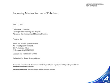
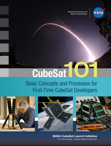
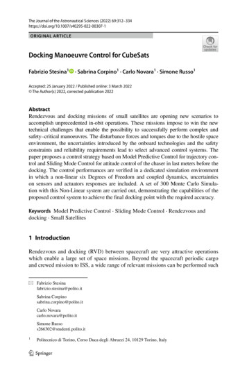
6U CubeSat Design Specification PROVISIONALThe CubeSat Program, Cal Poly SLO1.1.1Page 7IntroductionOverviewStarted in 1999, the CubeSat Project began as a collaborative effort between Prof. Jordi PuigSuari at California Polytechnic State University (Cal Poly), San Luis Obispo, and Prof. BobTwiggs at Stanford University's Space Systems Development Laboratory (SSDL). The purpose ofthe project is to provide a standard for design of picosatellites to reduce cost and developmenttime, increase accessibility to space, and sustain frequent launches. Presently, the CubeSatStandard is being used to develop picosatellites by high schools, universities, Governmentagencies and private companies all over the world. A 1U CubeSat is a 10 cm cube with a mass ofup to approximately 1.5 kg. To view the most updated versions of all CubeSat DesignSpecifications, please visit: http://cubesat.org and click on: “CubeSat Design Specification”.As Developers have continued to push the limits of CubeSats, there has been an increasingdemand for a larger satellite standard within the community. The 6U CDS provides a means toprovide standardized development for larger picosatellites. If you have any questions about thisdocument, please contact Cal Poly. You may visit the CubeSat website at http://cubesat.org formore information.Figure 1: 6U CubeSat Isometric view with highlighted optional Access Port locations1.2PurposeThe primary mission of the CubeSat Program is to provide access to space for small payloads.The primary responsibility of companies developing 6U Dispensers is to ensure the safety of theCubeSat and protect the launch vehicle (LV), primary payload, and other CubeSats during launch.CubeSat Developers should play an active role in ensuring the safety and success of CubeSatmissions by implementing good engineering practice, testing, and verification of their systems.Failures of CubeSats, 6U Dispensers, or interface hardware can damage the LV or a primarypayload and put the entire CubeSat Program in jeopardy. As part of the CubeSat Community, allparticipants have an obligation to ensure safe operation of their systems and to meet the designand minimum testing requirements outlined in this document.Requirements in this document will typically be superseded by the requirements of thelaunch provider.
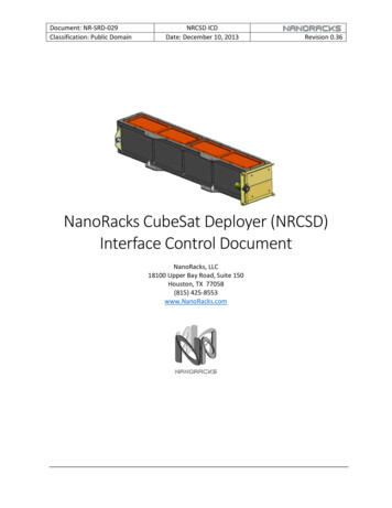
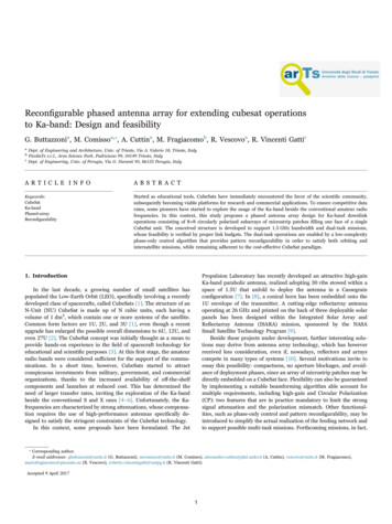
6U CubeSat Design Specification PROVISIONALThe CubeSat Program, Cal Poly SLOPage 81.3 Mission RequirementsMost CubeSat missions employ an organization to be responsible for all missioncoordination duties. That roll is usually referred to as the Mission Integrator, whoseresponsibilities can include coordinating safety documentation with Range Safety,interfacing with the CubeSat Developers, ICD requirement verifications with CubeSatDevelopers and the Launch Vehicle Contractor (LVC), acting as the point of contact forlicensing agencies, CubeSat to dispenser integration and testing, and coordinating withthe JSpOC for pre- and post-launch identification of each CubeSat in orbit. In essence,the Mission Integrator acts as the interface between the CubeSat Developer and the LVC,and will provide the official mission requirements to the CubeSat Developer.Although mission requirements are oftentimes similar to the requirements in the CDS, theCubeSat Developer will only be responsible for meeting the requirements provided by theMission Integrator. The requirements in this document are meant for preliminary designpurposes, and are written conservatively to allow for the best chances of compatibilitywith any launch vehicle.1.4Waiver ProcessWaivers are required by any spacecraft deviating from the specifications defined in the missionrequirements. Typically, the Mission Integrator will review the request with guidance from theLVC, resolve any questions, and determine if there are any additional tests, analyses or costs tosupport the waiver. This process is only valid after the CubeSat has been manifested on a mission,and the Mission Integrator is known.If the CubeSat has not been manifested yet and deviates from a requirement in the CDS, theDeveloper can complete the waiver inquiry request form (see appendix A) and submit it to CalPoly (cubesat@gmail.com) for an informal review. Cal Poly cannot make a determination as towhether the deviation will be acceptable to a future launch vehicle provider, but can provideguidance.Developers should realize that each requirement deviation potentially reduces the chances offinding a suitable launch opportunity.
6U CubeSat Design Specification PROVISIONALThe CubeSat Program, Cal Poly SLOFigure 2: CubeSat Standard Deviation Wavier Process Flow DiagramPage 9
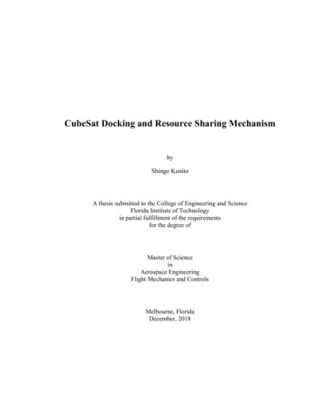
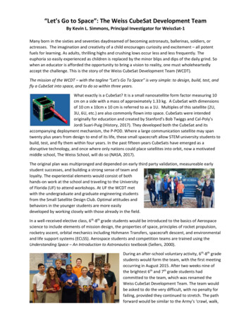
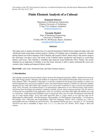
6U CubeSat Design Specification PROVISIONALThe CubeSat Program, Cal Poly SLO2.2.1Page 106U DispenserInterfaceThe 6U Dispenser is designed to carry a standard 6U CubeSat and serve as the interface betweenthe CubeSat and LV. Essentially, it’s a rectangular box that utilizes a hinged door and springmechanism to deploy its payload. A deployment signal sent from the LV actuates the releasemechanism to open the door, and the CubeSat is ejected from the dispenser.Multiple companies are developing 6U Dispensers which all adhere to one of two standardizedconstraint systems. The first is very similar to the rail system utilized by the Poly PicosatelliteOrbital Deployer (P-POD), and is used on the Tyvak and Innovative Solutions In Space (ISIS)dispensers. The second system, developed by Planetary Systems Corporation (PSC), utilizes twothinner rails henceforth referred to as ‘tabs’ that run along the length of the CubeSat. The PSC 6UDispenser employs a constraint mechanism that clamps onto these tabs and, when integrated,creates a stiff invariant load path.In both cases, the deployment force is provided by a main spring driving the internal pusher plate.The pusher plate, in turn, interfaces with the CubeSat, which glides along the 6U Dispenser railsas it’s ejected into orbit. Mechanical requirements for the rail system CubeSat are outlined inSection 3.2, and the mechanical requirements for tabbed CubeSats can be found atplanetarysystemcorp.com. Developers are encouraged to explore both options to determine whichis optimal for their needs. Due to the mechanical differences in dispenser designs, CubeSatsmight not be compatible with both types of dispensers.Figure 3a, 3b and 3c: Three Dispensers for 6U CubeSats designed by Planetary Systems Corporation(left) ISIS (center) and Tyvak (right)
6U CubeSat Design Specification PROVISIONALThe CubeSat Program, Cal Poly SLO3.Page 11CubeSat Specification3.1 General Requirements3.1.1 All parts shall remain attached to the CubeSats during launch, ejection and operation. Noadditional space debris will be created.3.1.23.1.3No pyrotechnics shall be permitted.3.1.43.1.5Propulsion systems shall have at least 3 independent inhibits to activation.3.1.63.1.7CubeSat hazardous materials shall conform to AFSPCMAN 91-710, Volume 3.3.1.8Note: Some launch vehicles hold requirements on magnetic field strength. As a generalguideline, it is advised to limit the magnetic field outside the CubeSat static envelope to0.5 Gauss above Earth’s magnetic field, while the CubeSat is integrated in the dispenser.3.1.9The CubeSat shall be designed to accommodate ascent venting per ventable volume/area 2000 inches.Any propulsion systems shall be designed, integrated, and tested in accordance withAFSPCMAN 91-710 Volume 3.Total stored chemical energy will not exceed 100 Watt-Hours.3.1.5.1 Note: This requirement is derived from the Federal Aviation Administration (FAA)requirement for lithium battery capacities that are allowed to be hand carried on tocommercial aircraft.CubeSat materials shall satisfy the following low out-gassing criterion to preventcontamination of other spacecraft during integration, testing, and launch. A list of NASAapproved low out-gassing materials can be found at: http://outgassing.nasa.gov3.1.7.1 CubeSat materials shall have a Total Mass Loss (TML) 1.0 %3.1.7.2 CubeSat materials shall have a Collected Volatile Condensable Material (CVCM) 0.1%
6U CubeSat Design Specification PROVISIONALThe CubeSat Program, Cal Poly SLO3.2Page 12CubeSat Mechanical Requirements6U CubeSats are picosatellites with dimensions and features outlined in the 6U CubeSatSpecification Drawing (Appendix B). These requirements are applicable for all dispensers notutilizing the tab constraint method. CubeSats designed with tabs can find those specificrequirements at the PSC website (planetarysystemscorp.com). General features of all CubeSatswithout tabs include:3.2.1The CubeSat shall use the coordinate system as defined in Appendix B. The origin of theCubeSat coordinate system is located at the geometric center of the CubeSat.3.2.1.1 The 6U CubeSat configuration and physical dimensions shall be per the appropriatesection of Appendix B.3.2.23.2.3The –Z face of the CubeSat will be inserted first into the 6U Dispenser.No components on the yellow shaded faces shall exceed 10 mm normal to the surface.3.2.3.1 When completing a CubeSat Acceptance Checklist (CAC), protrusions will bemeasured from the plane of the rails.3.2.4Deployables shall be constrained by the CubeSat, not the 6U Dispenser.3.2.4.1 Note: This requirement is derived from launch vehicle requirements.3.2.53.2.63.2.73.2.8Rails shall have a minimum width of 8.5mm.Rails will have a surface roughness less than 1.6 µm.The edges of the rails will be rounded to a radius of at least 1 mm.At least 75% of the rail will be in contact with the 6U Dispenser rails. 25% of the railsmay be recessed, and no part of the rails will exceed the specification.3.2.9The maximum mass of a 6U CubeSat shall be 12.00 kg.3.2.9.1 Note: Larger masses may be evaluated by the Mission Integrator on a mission specificbasis.3.2.10 The CubeSat center of gravity shall be located within 4.5 cm from its geometric center inthe X direction, within 2 cm from its geometric center in the Y direction, and within 7 cmfrom its geometric center in the Z direction3.2.11 Typically, Aluminum 7075, 6061, 6082, 5005, and/or 5052 are used for both the mainCubeSat structure and the rails. If materials other than aluminum are used, the CubeSatDeveloper should contact the Mission Integrator or dispenser manufacturer.3.2.12 The CubeSat rails and standoff, which contact the 6U Dispenser rails and ejector plate,shall be hard anodized aluminum to prevent any cold welding within the 6U Dispenser.
CubeSat Design Specification Rev. 1The CubeSat Program, Cal Poly SLO3.3Page 13Electrical RequirementsElectronic systems will be designed with the following safety features. These requirements areapplicable for all dispensers.3.3.1The CubeSat power system shall be at a power off state to prevent the CubeSat fromactivating any powered functions while integrated in the 6U Dispenser from the time ofdelivery to the LV through on-orbit deployment. CubeSat powered functionality includesa variety of subsystems such as Command and Data Handling (C&DH), RFCommunication, Attitude Determination and Control (ADC), and deployable mechanismactuation. CubeSat power systems include all battery assemblies, solar cells, and coin cellbatteries.3.3.1.1 Powered-On Real Time Clocks (RTC) may be permitted, if they satisfy the followingrequirements.3.3.3.1.1 Real time clock circuits shall be isolated from the CubeSat’s main power system.3.3.3.1.2 Real time clock frequencies shall be less than 320 kHz.3.3.3.1.3 Real time clock circuit(s) shall be current limited to less than 10 mA.3.3.2The CubeSat shall have, at a minimum, one deployment switch, which is actuated whileintegrated in the 6U Dispenser.3.3.2.1 In the actuated state, the CubeSat deployment switch shall electrically disconnect thepower system from powered functions.3.3.2.2 The deployment switch shall be in the actuated state at all times while integrated inthe 6U Dispenser.3.3.2.3 If the CubeSat deployment switch toggles from the actuated state and back, thesatellite shall reset to a pre-launch state, including reset of transmission anddeployable timers.3.3.3The CubeSat shall include a RBF pin. The RBF pin shall cut all power to the satelliteonce it is inserted into the satellite.3.3.3.1 The RBF pin shall protrude no more than 10 mm from the rails (or within theallowable CubeSat volume on tabbed dispensers, see planetarysystemscorp.com fordetails) when fully inserted into the satellite.3.3.3.2 Access to the CubeSat is not guaranteed during or after integration. The RBF pin shallbe removed from the CubeSat before integration into the 6U Dispenser, if thedispenser does not have access ports.3.3.43.3.5CubeSats shall incorporate battery circuit protection for charging/discharging to avoidunbalanced cell conditions. Additional manufacturer documentation and/or testing will berequired for modified, customized, or non-UL-listed cells.The CubeSat shall have at least three independent RF inhibits to prohibit inadvertentradio frequency (RF) transmission. An inhibit is a physical device between a powersource and a hazard. A timer is not considered an independent inhibit.3.3.5.1 Note: Some launch vehicle providers will only require one or two independentinhibits depending on the CubeSat’s RF power output. However, the use of threeindependent inhibits is highly recommended and can reduce required documentationand analyses.
6U CubeSat Design Specification PROVISIONALThe CubeSat Program, Cal Poly SLO3.4Page 14Operational RequirementsCubeSats will meet certain requirements pertaining to integration and operation to meet legalobligations and ensure the safety of other CubeSats. These requirements are applicable for alldispensers. Dispenser specific options are available, however additional options may limit launchopportunities.3.4.1Operators will obtain and provide documentation of proper licenses for use of radiofrequencies per their country’s requirements.3.4.1.1 For amateur frequency use, this requires proof of frequency coordination by theInternational Amateur Radio Union (IARU). Applications can be found atwww.iaru.org.3.4.1.2 Note: For CubeSats being operated in the U.S., amateur radio regulations can befound here: 3The CubeSat will comply with its country’s radio license agreements and restrictions.3.4.4All deployables such as booms, antennas, and solar panels shall wait to deploy aminimum of 30 minutes after the CubeSat's deployment switch(es) are activated during6U Dispenser ejection.3.4.5No CubeSats shall generate or transmit any RF signal from the time of integration intothe 6U Dispenser through 45 minutes after on-orbit deployment from the 6U Dispenser.However, the CubeSat can be powered on following deployment from the 6U Dispenser.3.4.6Private entities (non-U.S. Government) under the jurisdiction or control of the UnitedStates who propose to operate a remote sensing space system (satellite) may need to havea license as required by U.S. law. For more information html. Click on the Application Processlink under the Applying for a License drop down section to begin the process.3.4.7The Mission Integrator may conduct a fit check in which the CubeSat Developerhardware will be inspected and integrated into the 6U Dispenser or Test 6U Dispenser. Afinal fit check will be conducted prior to launch. The CubeSat Acceptance Checklist(CAC) can be used to verify compliance of the specification (CAC can be found in theappendix of this document or online at http://cubesat.org).CubeSat mission design and hardware shall be in accordance with NPR 8715.6 to limitorbital debris.3.4.3.1 Any CubeSat component shall re-enter with energy less than 15 Joules.3.4.3.2 Developers will be ready to provide orbital debris mitigation data if requested by thelicensing agency or Mission Integrator.3.4.3.3 Note: Analysis can be conducted to satisfy the above requirements with NASA DASsoftware, available at l
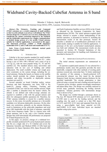
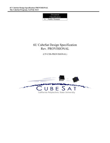
6U CubeSat Design Specification PROVISIONALThe CubeSat Program, Cal Poly SLO4.Page 15Testing RequirementsBefore detailing the typical CubeSat testing requirements, it is important to point out that alltesting levels and requirements are mission specific and vary with every launch. The examplesprovided in this document, are typically, the most stringent to encompass requirements from mostof the possible launch opportunities to date.Testing will be performed to meet the launch provider requirements as well as any additionaltesting requirements deemed necessary to ensure the safety of the CubeSats, 6U Dispenser, andthe primary mission. If the launch vehicle environment is unknown, The General EnvironmentalVerification Standard (GEVS, GSFC-STD-7000A) and SMC-S-016 can be used to derive testingrequirements. GSFC-STD-7000A and SMC-S-016 are useful references when defining testingenvironments and requirements. However, the test levels defined in GSFC-STD-7000A andSMC-S-016 are not guaranteed to encompass or satisfy all LV testing environments. Testrequirements and levels that are not generated by the launch provider or the Mission Integratorare considered unofficial. The launch provider testing requirements will supersede testingenvironments from any other source. Typically, all CubeSats will undergo the following tests.4.1Random VibrationRandom vibration testing shall be performed to the levels and duration as defined by the MissionIntegrator.4.2Thermal Vacuum BakeoutThermal vacuum bakeout shall be performed to ensure proper outgassing of components. Thetest specification will be defined by the Mission Integrator.4.3Shock TestingShock testing is typically not required for CubeSats. However, if necessary, shock testing shall beperformed as defined by the Mission Integrator.4.4Visual InspectionVisual inspection of the CubeSat and measurement of critical areas will be performed per theappropriate 6U CAC (Appendix C) or as defined by the Mission Integrator.4.5CubeSat Testing PhilosophyThis section outlines a conservative test flow approach for CubeSats to meet environmental testrequirements for launch. The CubeSat shall be subjected to either qualification or protoflighttesting as defined in the CubeSat Testing Flow Diagram, shown in Figure 4. The test levels anddurations will be supplied by the Mission Integrator.4.5.1QualificationQualification testing is performed on an engineering unit that is identical to the flight modelCubeSat. Qualification levels will be determined by the Mission Integrator. For guidelines toderive qualification test levels and durations, consult GSFC-STD-7000A and SMC-S-016. The
6U CubeSat Design Specification PROVISIONALThe CubeSat Program, Cal Poly SLOPage 16flight model will then be tested to Acceptance levels in a Test 6U Dispenser then integrated intothe flight 6U Dispenser for a final acceptance/workmanship random vibration test. Additionaltesting may be required if modifications or changes are made to the CubeSats afterqualification testing.4.5.2ProtoflightProtoflight testing is performed on the flight model CubeSat. Protoflight levels will bedetermined by the Mission Integrator. For guidelines to derive protoflight test levels anddurations, consult GSFC-STD-7000A and SMC-S-016. The flight model will be tested toProtoflight levels in a Test 6U Dispenser then integrated into the flight 6U Dispenser for a finalacceptance/workmanship random vibration test. The flight CubeSat SHALL NOT bedisassembled or modified after protoflight testing. Disassembly of hardware after protoflighttesting will require the Developer to inform the Mission Integrator to determine the path forward.Additional testing will be required if modifications or changes are made to the CubeSatsafter protoflight testing.4.5.3AcceptanceAfter delivery and integration of the CubeSat into the 6U Dispenser, additional testing will beperformed on the integrated system. This test ensures proper integration of the CubeSat into the6U Dispenser. The 6U Dispenser Integrator will coordinate and perform acceptance testing.Acceptance test levels will be determined by the Mission Integrator. For guidelines to deriveacceptance test levels and durations, consult GSFC-STD-7000A and SMC-S-016. The CubeSatSHALL NOT be de-integrated from the 6U Dispenser at this point. If a CubeSat failure isdiscovered, a decision to de-integrate the 6U Dispenser will be made by the Developers, in that6U Dispenser, and the Mission Integrator based on safety concerns. The Developer is responsiblefor any additional testing required due to corrective modifications to de-integrated 6U Dispensersand CubeSats.
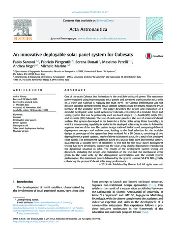
6U CubeSat Design Specification PROVISIONALThe CubeSat Program, Cal Poly SLOPage 17Figure 4: CubeSat General Testing Flow DiagramNote: CubeSat test flows will vary from mission to mission; the Mission Integrator will providethe CubeSat Developer with the approved test flow for a specific mission.
Page 186U CubeSat Design Specification PROVISIONALThe CubeSat Program, Cal Poly SLO5.OptionsDispenser specific options are available to support specific CubeSat mission requirements. Pleasecontact the dispenser provider for details about any options prior to incorporating them into your6U CubeSat design.5.1ISIS 6-POD DispenserThe 6-POD dispenser was developed by ISIS, a small satellite company based in the Netherlands.Its design is derived from the 1U and 3U dispensers also available from ISIS.5.2Planetary Systems Corporation Canisterized Satellite DispenserThe CSD was developed by Planetary Systems Corporation and is currently the only dispenseravailable that uses the tab system to constrain CubeSat payloads. Additional advantages of usingthe tab system include having an analyzable load path to the payload, and a flexible externalpayload shape.5.3Tyvak Nanosatellite Launch Adapter SystemThe Tyvak NLAS Mk. II design was derived from the NASA Ames Research Center NLAS Mk.I. The design incorporates lessons learned from the NLAS Mk. I and the Poly Picosatellite OrbitalDeployer (P-POD) designs.Options6-PODISISwww.isispace.nlAccess PortsCSDPlanetary vak.com Additional Mass Power/Data PortPurgeZ Constraint 6U AdditionalVolume X-Y Constraint
6U CubeSat Design Specification PROVISIONALThe CubeSat Program, Cal Poly SLOPage 19Available Option Descriptions:Access PortsAccess ports are used to physically access the satellite while the CubeSat isintegrated within the 6U dispenser. The access ports allow the RBF pins to beremoved post-integration into a 6U dispenser, and they can be used to visuallyverify separation switch engagement after the CubeSat has been integrated.Additional MassSome dispensers have been designed to accommodate a larger payload massthan this document specifies. Please refer to the dispenser website for specificmass limits. The mass limits of a dispenser are dependent on the dynamicenvironments of a launch.Power/Data PortThis option allows the CubeSat to electrically interface with the dispenserwhile integrated. For specific information regarding power-on capabilities,please refer to the di
missions by implementing good engineering practice, testing, and verification of their systems. Failures of CubeSats, 6U Dispensers, or interface hardware can damage the LV or a primary payload and put the entire CubeSat Program in jeopardy. As part of the CubeSat Community, all