Transcription
Reconfigurable phased antenna array for extending cubesat operationsto Ka-band: Design and feasibilityMARK⁎G. Buttazzonia, M. Comissoa, , A. Cuttina, M. Fragiacomob, R. Vescovoa, R. Vincenti GatticabcDept. of Engineering and Architecture, Univ. of Trieste, Via A. Valerio 10, Trieste, ItalyPicoSaTs s.r.l., Area Science Park, Padriciano 99, 34149 Trieste, ItalyDept. of Engineering, Univ. of Perugia, Via G. Duranti 93, 06125 Perugia, ItalyA R T I C L E I N F OA BS T RAC lityStarted as educational tools, CubeSats have immediately encountered the favor of the scientific community,subsequently becoming viable platforms for research and commercial applications. To ensure competitive datarates, some pioneers have started to explore the usage of the Ka-band beside the conventional amateur radiofrequencies. In this context, this study proposes a phased antenna array design for Ka-band downlinkoperations consisting of 8 8 circularly polarized subarrays of microstrip patches filling one face of a singleCubeSat unit. The conceived structure is developed to support 1.5 GHz bandwidth and dual-task missions,whose feasibility is verified by proper link budgets. The dual-task operations are enabled by a low-complexityphase-only control algorithm that provides pattern reconfigurability in order to satisfy both orbiting andintersatellite missions, while remaining adherent to the cost-effective CubeSat paradigm.1. IntroductionPropulsion Laboratory has recently developed an attractive high-gainKa-band parabolic antenna, realized adopting 30 ribs stowed within aspace of 1.5U that unfold to deploy the antenna in a Cassegrainconfiguration [7]. In [8], a conical horn has been embedded onto the1U envelope of the transmitter. A cutting-edge reflectarray antennaoperating at 26 GHz and printed on the back of three deployable solarpanels has been designed within the Integrated Solar Array andReflectarray Antenna (ISARA) mission, sponsored by the NASASmall Satellite Technology Program [9].Beside these projects under development, further interesting solutions may derive from antenna array technology, which has howeverreceived less consideration, even if, nowadays, reflectors and arrayscompete in many types of systems [10]. Several motivations invite toessay this possibility: compactness, no aperture blockages, and avoidance of deployment phases, since an array of microstrip patches may bedirectly embedded on a CubeSat face. Flexibility can also be guaranteedby implementing a suitable beamforming algorithm able account formultiple requirements, including high-gain and Circular Polarization(CP): two features that are in practice mandatory to limit the strongsignal attenuation and the polarization mismatch. Other functionalities, such as phase-only control and pattern reconfigurability, may beintroduced to simplify the actual realization of the feeding network andto support possible multi-task missions. Forthcoming missions, in fact,In the last decade, a growing number of small satellites haspopulated the Low-Earth Orbit (LEO), specifically involving a recentlydeveloped class of spacecrafts, called CubeSats [1]. The structure of anN-Unit (NU) CubeSat is made up of N cubic units, each having avolume of 1 dm3, which contain one or more systems of the satellite.Common form factors are 1U, 2U, and 3U [1], even though a recentupgrade has enlarged the possible overall dimensions to 6U, 12U, andeven 27U [2]. The CubeSat concept was initially thought as a mean toprovide hands-on experience in the field of spacecraft technology foreducational and scientific purposes [3]. At this first stage, the amateurradio bands were considered sufficient for the support of the communications. In a short time, however, CubeSats started to attractconspicuous investments from military, government, and commercialorganizations, thanks to the increased availability of off-the-shelfcomponents and launches at reduced cost. This has determined theneed of larger transfer rates, inviting the exploration of the Ka-bandbeside the conventional S and X ones [4–6]. Unfortunately, the Kafrequencies are characterized by strong attenuations, whose compensation requires the use of high-performance antennas specifically designed to satisfy the stringent constraints of the CubeSat technology.In this context, some proposals have been formulated. The Jet⁎Corresponding author.E-mail addresses: gbuttazzoni@units.it (G. Buttazzoni), mcomisso@units.it (M. Comisso), alessandro.cuttin@phd.units.it (A. Cuttin), vescovo@units.it (M. Fragiacomo),mariofragiacomo@picosats.eu (R. Vescovo), roberto.vincentigatti@unipg.it (R. Vincenti Gatti).Accepted 9 April 20171
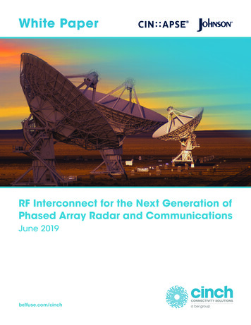
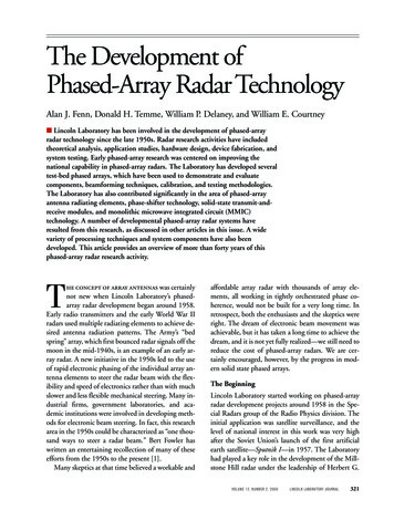
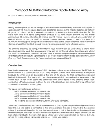
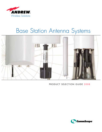
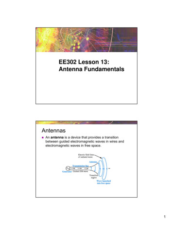
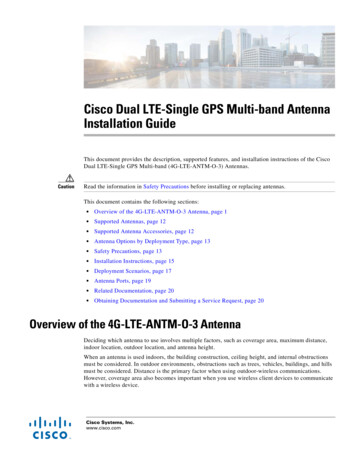
Acta Astronautica 137 (2017) 114–121G. Buttazzoni et al.will not be limited to conventional LEO orbiting, requiring high-gainnarrow-beam antenna patterns, but are also expected to involveconstellations of CubeSats [11,12], requiring patterns with wider mainlobes to enable the identification of other nearby CubeSats forintersatellite communication purposes.In light of these considerations, this paper presents the design of aKa-band phased antenna array providing CP and pattern reconfigurability to support downlink and intersatellite CubeSat missions.Preliminary experimental and numerical results combined with illustrative link budgets are also reported to discuss the applicability of thearray technology to next generation Ka-band CubeSats.The paper is organized as follows. Section 2 presents the arraystructure. Section 3 introduces the reconfiguration functionalities.Section 4 discusses the feasibility aspects. Section 5 remarks the mostrelevant conclusions.patches in orientation and phase at 0 , 90 , 180 , and 270 [17,18].The sequential phases are achieved by quarter-wavelength delay linesand optimizing the feeding network by CST Microwave Studioto minimize the losses. In particular, the lengths a1, , a4 inFig. 2(a) are evaluated to ensure that the relationshipsa2 a4 λg /4 a1 a4 a2 a3 λg /4 a1 a3 λg /2 be satisfiedfor the guided wavelength λg 5.616 mm .The simulated and experimental performance obtained from afabricated prototype (Fig. 3), shows that the subarray provides a10 dB-bandwidth larger than 1.5 GHz (Fig. 4(a)), thus matching thehigh-bandwidth requirement, and a maximum gain of 11.54 dB withan RHCP/LHCP isolation of 12.51 dB (Fig. 4(b) and (c)). A satisfactorylevel of polarization purity is also obtained, since both the simulatedand measured Axial Ratios (ARs) remain within 3 dB in the mainlobe.Except for few discrepancies in the φ 90 half-plane (Fig. 4(c)) dueto a partially unshielded cable connector on the back of the prototype, agood agreement between simulations and measurements may beobserved.For the design of the full array, the surface that can be actuallyoccupied at the net of the mandatory CubeSat rails [1], is a square ofedge R 85 mm. Since the maximum size of a subarray is ux 9.024 mm(Fig. 2(a)), an array of N 8 8 64 elements may be placed on theavailable surface by selecting a distance r 10.625 mm between thefeeding points of two adjacent subarrays, in order to maintain adistance of at least λ/5 between their sides (Fig. 5). To account forthe mutual coupling due to the closeness between the elements, the ϑ(zenith) and φ-(azimuth) components Enϑ (Ω ) and Enφ (Ω ) of the electricfar-field of the n-th subarray (n 1, ,N) in the direction Ω (ϑ, φ) arecalculated accounting for the presence of the other adjacent subarraysby using the method in [19]. This method exploits the linear relationship between the array and the element patterns to estimate Enϑ (Ω ) andEnφ (Ω ) by a suitable electromagnetic software (in our case CSTMicrowave Studio) using a unity-voltage zero-phase feed for the n-thelement and a zero-voltage feed for the remaining N 1 elements.Besides, to obtain a compact formulation, Enϑ (Ω ) and Enφ (Ω ) includealso the phase shift due to the position inside the array. Hence,denoting as j the imaginary unit and as α [α1, , αN ] the vector ofthe complex excitations of the array elements, the RHCP componentE1 (α; Ω ) and the LHCP component E2 (α; Ω ) are jointly expressed, fori 1,2, as:2. Array structureSince the design of spacecraft subsystems is strictly dependent onthe mission objectives, we consider, as a baseline for the developmentof the array structure, a broadside configuration, which can be suitablyadapted to different tasks. With this choice, in this section, we firstdesign the array structure by accounting for the operational frequencyand the size constraints, while, in Section 3, we synthesize the requiredradiation patterns by accounting for the mission purposes.The array structure consists of a planar array that fits to one face ofa 1U CubeSat [14], so as to make the proposed antenna system suitablefor missions adopting any of the allowed form factors from 1U to 27U.A mechanical prototype built at PicoSaTs s.r.l. [13], displays the facechosen to accommodate the array (Fig. 1), which consists of Nsubarrays, each formed by four microstrip patches. The design of thesubarray with the corresponding parameters is reported in Fig. 2(a)and (b). The single patch, realized to operate in the Ka-band at thefrequency of 37 GHz, corresponding to a wavelength λ 8.108 mm , isdeveloped using the mitering method [15], to obtain Right-Hand CP(RHCP) [16]. For manufacturing reasons and to reduce the couplingeffects with the feeding line due to the high operational frequency, athree-layer design is considered, with two DiClad 880 substrates and amid prepreg I-TERA MT solding substrate. To better match the RHCPconstraint, minimize Left-Hand CP (LHCP), and to increase thebandwidth, the subarray building block is developed using the sequential phase-rotation technique by sequentially arranging the fourEi (α; Ω ) 12N αn [Enϑ (Ω) j ( 1)i Enφ (Ω)],n 1(1)which analytically describes the RHCP/LHCP patterns provided by thearray structure for a given excitation vector α .3. Pattern synthesisOnce the array structure is designed, the excitations of the Nsubarrays are synthesized to generate two different patterns forsupporting a dual-task mission. Next-generation CubeSats are in factexpected to perform not only LEO orbiting, but also internetworkingoperations, where constellations of small satellites exchange scientificor commercial data. Accordingly, a task t 1 consists in communicatingwith the ground station by a pattern with a narrow, high-gain beam. Atask t 2 consists in realizing an intersatellite link, which takesadvantage of a pattern with a broader beam and a lower gain toproperly search the neighboring CubeSats. The aim is to satisfy thegeneric task t by simply orienting the CubeSat face containing the arraytowards the appropriate region of space (i.e., towards the groundstation for t 1, or towards the satellites’ constellation for t 2) bymeans of the on-board Attitude Determination and Control Subsystems(ADCSs), and then selecting the proper excitation vectorαt [α1, t , , αN , t ]. Thus, two sets of excitations, α1 and α2 , must besynthesized to enable the reconfigurability of the pattern according toFig. 1. Mechanical mock-up of a 1U CubeSat: the exposed face of the frame (i.e., the onewithout solar panels) is selected to accommodate the developed antenna array. Picturecourtesy of PicoSaTs s.r.l. [13].2115
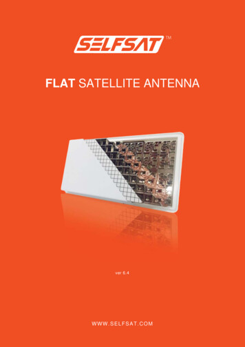
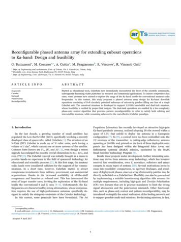
Acta Astronautica 137 (2017) 114–121G. Buttazzoni et al.Fig. 2. Subarray building block: (a) front-view design, (b) side-view design.where Mt is the RHCP pattern mask that imposes the desiredmaximum gain .t , side-lobe level (SLL) ρt, and Half-PowerBeamWidth (HPBW) ωt for the task t. In particular, the imposedvalues are . 1 25 dB, ρ1 ζ1 15 dB, ω1 4 , (task 1, narrow beamand high gain), . 2 15 dB, ρ2 ζ2 5 dB, ω 2 20 (task 2, widerbeam and lower gain). This problem is solved by first identifying twosets: a set U, whose elements satisfy conditions (2a)–(2c), and a set V,whose elements account for the array structure by (1). Then, thealgorithm in [20] is applied to perform an iterative sequence ofalternate projections onto U and V to find the α1 and α2 vectors thatminimize the distance between the two sets. The synthesized excitationphases are realized by the feeding network in Fig. 6. The integer k neareach subarray feeding point identifies the derived phase shift χk kπ /8(quantized to a multiple of π /8 to simplify the actual realization), whichhas been implemented by a stripline of length Δk χk /(2βg ) kλg /32 ,being βg 2π / λg the wave number referred to the guided wavelength.Two switches are also inserted to enable pattern reconfigurability, sinceall elements are active for t 1, while just the four ones inside thedashed square are active for t 2. To maintain the phasing of thefeeding network for t 1, the second switch is provided with a properlydesigned delay line of length Δf .Fig. 7 reports the simulated performance of the full structure (arrayand feeding network). In particular, Fig. 7(a) shows that the reconfigurable array maintains a satisfactory return loss, providing, for t 1(Fig. 7(b)), a maximum gain of 24.04 dB, an HPBW of 4 , an LHCP/RHCP isolation of 13.47 dB, an AR of 3.75 dB, and, for t 2 (Fig. 7(c)),a maximum gain of 13.28 dB, an HPBW of 20 , an LHCP/RHCPisolation of 13.33 dB, an AR of 3.80 dB. Thus, it guarantees, beside thegain, a satisfactory polarization purity also for the second task,characterized by a wider mainlobe. These results confirm that aFig. 3. Subarray building block: fabricated prototype.the selected task. For each task, the LHCP field represents theundesired radiation, so its amplitude is kept below a given thresholdζt. Furthermore, the amplitude αn, t and the phase arg(αn, t ) of the n-thelement during the task t are properly constrained to reduce thecomplexity of the feeding network. More precisely, αn, t is forced tobelong to the set {0, 1} (on/off condition), thus, all the actually activeelements have an identical amplitude, and the synthesis is hencecarried out by phase-only control. In summary, the formulated dualtask problem consists in finding, for each t 1,2 value, an excitationvector αt satisfying the constraints: E1 (αt ; Ω ) M t ,(2a) E2 (αt ; Ω ) ζt ,(2b) αn, t {0, 1}, n 1, , N ,(2c)3116
Acta Astronautica 137 (2017) 114–121G. Buttazzoni et al.Fig. 4. Subarray performance: (a) return loss, (b) 2D gain pattern cuts in the x z plane, (c) 2D gain pattern cuts in the y z plane.Fig. 5. Array structure: front view.Fig. 6. Array structure: back view (feeding network).reconfigurable antenna array embedded on a CubeSat face may be ableto satisfy the pattern requirements of forthcoming dual-task missions.4.1. Link budgetsThe discussion moves from two illustrative link budgets, which aredeveloped for the two considered tasks: the CubeSat-ground stationdownlink (Table 1) and the intersatellite communication (Table 2).Even though the two tasks have some common parameters and thecorresponding budgets may look similar at a first glance, they exhibitsignificant differences when it comes to the evaluation of the propagation losses and receivers’ features.Once the input power and the transmitting antenna parameter (that4. Feasibility aspectsTo get a clearer view of the actual applicability of the designedreconfigurable Ka-band array in CubeSat scenarios, some specificimplementation aspects relative to the link budgets and the competingreflectarray technology deserve to be investigated in more detail.4117
Acta Astronautica 137 (2017) 114–121G. Buttazzoni et al.Fig. 7. Reconfigurable array performance: (a) return loss, (b) 2D gain pattern cuts for task 1, (c) 2D gain pattern cuts for task 2.is, the gain in the presence of the feeding network, the HPBW, and thepolarization losses), are established for each task, a detailed link budgetat the spacecraft side has to account for the pointing accuracy. Sincethe antenna is conceived to fit on a face of the spacecraft, its pointing isexpected to be provided by the ADCS. Commercially available ADCSstypically provide a pointing accuracy of 0.5 or better [22], thus theimpact of the pointing losses on the Effective Isotropic Radiated Power(EIRP) is limited for both tasks.The propagation path is the major responsible for the losses, whichshall be compensated by the transmitting and receiving subsystems.Whereas, in the intersatellite link, it is safe to assume that the overallpath losses are given mainly by the Free Space Path Loss (FSPL), this isnot the case for the downlink from space to Earth, where additionalattenuations come into play because of the presence of the Earth'satmosphere. Moreover, given the low-earth orbit, the performance ofthe link during the access is not uniform, because the slant rangebetween the ground station and the spacecraft varies from 400 km atthe zenith to over 2000 km at the horizon, therefore yielding asignificant variation of the FSPL during the in-view period. To takethis into account, the budget for task 1 presents as a reference theaverage value of the FSPL corresponding to the average distance,meaning that the margin will improve when the satellite approachesthe zenith, and will worsen when the satellite is closest to the horizon.Also, it may be noticed that the additional atmospheric attenuations inTable 1 relative to rain and clouds hold in pessimistic faded scenarios,while, in clear sky conditions, these attenuations are considerablyreduced, thus increasing the available margin.At the receiving end, in the task 1, the antenna is considered to be aparabolic reflector with a 70% efficiency and a pointing accuracy of 0.1 [25], while, in the task 2, it is considered as an antenna system identicalto the transmitting one. Distinct environmental conditions, referred tothe Earth surface (task 1) and to the exosphere (task 2), areexperienced by the two receiver sides, thus considerably differentiatingthe corresponding system noise temperatures even in the presence ofan identical receiver. For both tasks, the selected receiver exploits oneof the novel MODulation-CODe (MODCOD) configurations offered bythe recently released Digital Video Broadcasting (DVB)-S2X extension[27]. This amendment extends the Signal-to-Noise Ratio (SNR) working conditions with respect to the original DVB-S2 standard, until 10 dB, thus allowing the connectivity in the presence of significantatmospheric absorptions, which may sometimes arise during Ka-bandcommunications. In particular, the receiver sides of the developed linkbudgets rely on the newly available configuration consisting of aquadrature phase-shift keying modulation in combination with a lowdensity parity check/Bose Chaudhuri Hocquenghem joint encoder ofrate 2/9, which ensures a reliable communication at 100 Mbps [26].This choice, considered in conjunction with the available SNR resultingfrom the designed antenna system, leaves a satisfactory link margin forboth tasks. To this purpose, it should also be noted that the selectedcommunication protocol supports the adaptive coding and modulation,thus potentially allowing the full exploitation of the excess link marginby activating higher throughput MODCODs that require higher (Eb / N0 )rvalues. From a technological point of view, the premises to adopt a Kaband communication link with the DVB-S2X standard are already inplace. One proposal for a Ka-band CubeSat transceiver is presented in[28], and consists in mixing an intermediate-frequency signal at 1 GHzwith the second harmonic generated by a local oscillator operating athalf of the desired radio-frequency. Exploiting this approach, thepresence on the market of components operating at frequencies beyond15 GHz enables the achievement of frequencies above 30 GHz [29]. Asecond proposal, offering a range of operating frequencies between 17and 40 GHz, relies on a software defined radio platform [30], thusallowing the upgrade to the advanced MODCODs specified in the DVBS2X standard. In this context, an antenna array seems hence perfectlysuited for enabling the support of dual-task missions in next generationKa-band nanosatellites.5118
Acta Astronautica 137 (2017) 114–121G. Buttazzoni et al.4.2. Arrays and reflectarraysto be serviceable.From the point of view of the losses, arrays are not subject tospillover (anyway minimized in the ISARA design), feed package loss,and aperture blockage, which, according to the currently availabledesign, may instead partly affect ISARA because the feed and part ofthe CubeSat envelope may be not completely outside of the reflectarrayaperture ([9], Fig. 1). However, these three factors, even combined,have in general an impact lower than that of the losses, due to thefeeding network and the patch substrates, that characterize antennaarrays. This difference provides large benefits to ISARA, which achievesa gain of 33 dB with a 3U CubeSat. A fair comparison should anywayconsider that the presented phased-array relies on a 1U CubeSat toprovide a basic module, which might be replicated on more faces of anNU spacecraft to increase the gain.From the versatility point of view, phased-arrays may be employedto support multi-task missions by pattern reconfigurability. A possibility exploited in the presented design, but not even considered in theISARA proposal.Finally, from the point of view of the space available for the solarcells, one may observe that the solar panels printed on the back of theISARA reflectarray cover an area equivalent to nine 1U CubeSat faces,while five 1U CubeSat faces are available for solar panels in theproposed design. However, a scaling of the developed phase-array toa 3U CubeSat, reveals that, even considering three faces covered bythree replicas of the array, eleven faces would remain accessible to solarcells. Therefore, the compactness and the conformability of the phasedarray do not imply limitations for the energy supply of the CubeSatsystem.The applicability of phased-arrays to Ka-band CubeSats may befurther deepened by considering the competing antenna technologybased on reflectarrays [10]. In this field, the most advanced solution isthe ISARA proposal, for which, even if the project is still underdevelopment, some preliminary numerical results are already available[9]. A comparative description of these two systems may be useful tobetter outline benefits and drawbacks of each technology in terms ofmechanics, losses, versatility, and space available for the solar cells.From a mechanical point of view, both antenna systems do notoccupy space inside the CubeSat before the launch (except for the smallpackaged feed of ISARA), thus leaving more volume available to theother subsystems. ISARA requires the mechanical deployment of thepanels and of the feed, which might represent a critical phase of themission that may suffer from vibrations, heat variations, or otherpossible mechanical setbacks due to the launch or the space environment. Conversely, the array solution is ready to be operated as it isintegrated on the spacecraft, without requiring any further interventionTable 1Link budget for task 1 (CubeSat-ground station downlink).Table 2Link budget for task 2 (intersatellite communication).6119
Acta Astronautica 137 (2017) 114–121G. Buttazzoni et al.[17] J. Huang, A. Ka-band, circularly polarized high-gain microstrip array antenna,IEEE Trans. Antennas Propag. 43 (1) (1995) 113–116.[18] A. Chen, Y. Zhang, Z. Chen, C. Yang, Development of a Ka-band widebandcircularly polarized 64-Element microstrip antenna array with double applicationof the sequential rotation feeding technique, IEEE Antennas Wirel. Propag. Lett. 10(2011) 1225–1536.[19] M. Comisso, R. Vescovo, Fast iterative method of power synthesis for antennaarrays, IEEE Trans. Antennas Propag. 57 (7) (2009) 1952–1962.[20] G. Buttazzoni, R. Vescovo, An efficient and versatile technique for the synthesis of3D copolar and crosspolar patterns of phase-only reconfigurable conformal arrayswith DRR and near-field control, IEEE Trans. Antennas Propag. 62 (4) (2014)1640–1651.[22] Clyde Space. (last access: 21st Feb. 2017). URL 〈https://www.clyde.space/〉.[25] Comtech Telecommunications Corp., (last access: 21st Feb. 2017). URL 〈http://www.telecomsys.com/〉.[26] European Space Agency, ARTES 5.1 Statement of work: Miniaturised Ka-band FSStransponder for small satellites 5E.001, 2015.[27] ETSI DVB-S2X Draft Std, Digital Video Broadcasting (DVB); Second generationframing structure, channel coding and modulation systems for broadcasting,interactive services, news gathering and other broadband satellite applications;Part 2: DVB-S2 Extensions, 2014.[28] M. Mc Nicholas, J. De Luna, R. Manno, Y.-H. Shu, Low cost Ka-band transmitterfor CubeSat systems, in: Proceedings of the IEEE Topic. Work. Internet of Space,2017.[29] 18 GHz Microwave PLL Synthesizer, Analog Devices. (last access: 21st Feb. 2017).URL 30] SWIFT-KTX: High Throughput Software-Defined K-band Communications,Tethers Unlimited, Inc., (last access: 21st Feb. 2017). URL 〈http://www.tethers.com/SpecSheets/Brochure SWIFT KTX.pdf〉.5. ConclusionsA reconfigurable antenna array for Ka-band CubeSats has beenpresented. The proposed structure provides interesting benefits interms of bandwidth, polarization purity, and versatility, which suggestpromising possibilities for the array technology in forthcoming Kaband nanosatellites. The obtained encouraging results may be strengthened observing that the elements put beside the designed antennasystem and adopted to develop the link budgets for a dual-task missionare not high-end components. Hence, low-cost arrays may certainlycooperate with the currently available off-the-shelf devices, thusmaintaining the cost-effective requirement of the CubeSat communication system.Further in-depth analyses might be inferred after the investigationof the impact of the manufacturing tolerances on a physical device,whose realization may be however trustfully carried out on the basis onthe here discussed feasibility study and of the fabricated subarrayprototype. In conclusion, the flexibility of arrays in providing advancedfunctionalities combined with the recent innovations in the otherrelated CubeSat technologies, such as ADCSs and miniaturized Kaband transponders, may represent a really inviting opportunity toaccomplish multi-task missions at reasonable costs and reduceddeployment risks.Further readingAcknowledgements[1] A.C. Ludwig, A simple graph for determining polarization loss, Microw. J. 19 (9)(1976) 63.[2] W.J. Larson, J.R. Wertz, Space Mission Analysis and Design, Microcosm PressSpringer, 1999.[3] Centre Nat. Etudes Spatiales, ITU-R Propag. models software library, 2010.This work is partly supported by the Italian Ministry of University andResearch (MIUR) within the project FRA 2015 (University of Trieste, Italy),entitled “Peer-to-peer Millimeter-Wave Communications in 5G Networks:Theoretical Modeling and Algorithms for Massive MIMO Systems.” Theauthors would also like to thank Prof. Federico Alimenti for the helpfulsupport in the experimental development of the subarray feed.Giulia Buttazzoni received the Laurea degree (summacum laude) in Telecommunication Engineering and thePh.D. degree in Information Engineering from theUniversity of Trieste (Italy), in 2008 and 2013, respectively. She is currently a researcher at the Department ofEngineering and Architecture of the University of Trieste.Her research interests involve antenna array synthesis andnumerical methods for electromagnetic fields.References[1] California Polytech. State Univ., CubeSat design specif.: Rev. 13, 2015.[2] R. Hevner, W. Holemans, J. Puig-Suari, R. Twiggs, An advanced standard forCubeSats, in: Proceedings of the AIAA/USU Conf. Small Satellites, 2011.[3] M.A. Viscio, N. Viola, S. Corpino, F. Stesina, S. Fineschi, F. Fumenti, C. Circi,Interplanetary CubeSats system for space weather evaluations and technologydemonstration, Acta Astronaut. 104 (2014) 516–525.[4] A. Canabal, R.P. Jedlicka, A.G. Pino, Multifunctional phased array antenna designfor satellite tracking, Acta Astronaut. 57 (2005) 887–900.[5] A. Babuscia, B. Corbin, M. Knapp, R. Jensen-Clem, M. van de Loo, S. Seager,Inflatable antenna for cubesats: motivation for development and antenna design,Acta Astronaut. 91 (2013) 322–332.[6] F. Tubbal, R. Raad, K. Chin, A survey and study of planar antennas for picosatellites, IEEE Access 3 (2015) 2590–2612.[7] J.F. Sauder, N. Chahat, R. Hodges, E. Peral, Y. Rahmat-Samii, M. Thomson,Designing, building, and testing a mesh Ka-band parabolic deployable antenna(KaPDA) for CubeSat, in: Proceedings of the AIAA Aerospace Sciences Meet., 2015.[8] J.A. King, K. Leveque, M. Bertino, J. Kim, H. Aghahassan, Ka-band for CubeSats,in: Proceedings of the AIAA/USU Conf. Small Satellites, 2015.[9] R.E. Hodges, D.J. Hoppe, M.J. Radway, N.E. Chahat, Novel deployable reflectarrayantennas for CubeSat communications, in: Proceedings of the IEEE MTT-S Int.Microw. Symp., 2015.[10] R.L. Haupt, Y. Rahmat-Samii, Antenna array developments: a perspective on thepast, present and future, IEEE Antennas Propag. Mag. 57 (1) (2015) 86–96.[11] A. Babuscia, K.-M. Cheung, D. Divsalar, C. Lee, Development of cooperativecommunication techniques for a network of small satellites and CubeSats in deepspace: the SOLARA/SARA test case, Acta Astronaut. 115 (2015) 349–355.[12] C. Underwood, S. Pellegrino, V.J. Lappas, C.P. Bridges, J. Baker, Using CubeSat/micro-satellite technology to demonstrate the Autonomous Assembly of aReconfigurable Space Telescope (AAReST), Acta Astronaut. 114 (2015) 112–122.[13] PicoSaTs CubeSat Enterprise. (last access: 21st Feb. 2017). [link] URL 〈http://picosats.eu/〉.[14] R. Martinez Rodriguez-Osorio, E.Fueyo Ramírez, A hands-on education project:antenna design for inter-CubeSat communications, IEEE Antennas Propag. Mag.54 (5) (2012) 211–224.[15] R. Garg, P. Bhartia, I. Bahl, A. Ittipiboon, Microstrip antenna design handbook,Artech House Antennas and Propagation Libra
N-Unit (NU) CubeSat is made up of N cubic units, each having a volume of 1 dm3, which contain one or more systems of the satellite. Common form factors are 1U, 2U, and 3U [1], even though a recent upgrade has enlarged the possible overall dimensions to 6U, 12U, and even 27U [2]. The CubeSat concept was initially thought as a mean to