Transcription
ABI COOLER SYSTEM PROTOFLIGHTPERFORMANCER.Colbert, G.Pruitt, T.Nguyen, J.RaabNorthrop Grumman Space Technology1One Space Park, Redondo Beach, CA, USA 90278S. Clark, P. RamseyITT Industries Space Systems Division1919 West Cook Road, Fort Wayne, IN, USA 46801ABSTRACTNorthrop Grumman has developed and tested the Advanced Baseline Imager (ABI) PulseTube Cooler System, a two-stage pulse tube cooler, for space applications. The ABI coolersystem incorporates an integral High Efficiency Cryocooler (HEC) pulse tube cooler and aremote coaxial cold head. The two-stage cold head was designed to provide large cooling powerat 53K and 183K, simultaneously.This paper presents the results of data collected on the two protoflight module (PFM-1 andPFM-2) coolers during acceptance testing. Tests conducted on the PFM coolers included appliedvibration, survival at non-operational temperature extremes, thermal performance measurementsover a range of operational temperatures and temperature stability tests. Designed for a 10-yearlife, the ABI coolers have the capability to provide 1.9-2.3W of cooling at 53K and between5.1W and 8.0W of cooling at 183K; while rejecting to 300K with less than 186 W input power tothe cooler control electronics. The ABI PFM-1 and PFM-2 coolers provided the cooling at 53Kand 183K at input power levels of 162 and 170 W respectively. Both coolers demonstrated shortand long term temperature stability of less than 60mKp-p. These protoflight module coolers arethe first flight set of coolers delivered to ITT for the ABI program for the NOAAGeosynchronous Operational Environmental Satellite – R Series (GOES R) mission, developedthrough a NASA contract.1Northrop Grumman Space Technology is part of the ITT Advanced Baseline Imager (ABI) team. ITTleads the team as the prime contractor and has overall responsibility for the program development effort.ABI is a NOAA funded, NASA administered contract.Approved for public release; NG 08-0272, 4/3/08.
COOLER SYSTEM DESCRIPTIONThe ABI Pulse Tube Cooler System design is a derivative of the HEC cooler that iscurrently on-orbit on the Japanese Advanced Meteorological Imager (JAMI). NorthropGrumman (formerly TRW), evolved the design from on-orbit pulse tube cooler designs that thecompany has built and launched over the past decade. No failures have been experienced on anyof these coolers on the seven satellite systems launched to date; with some coolers nowapproaching 11 years of failure-free operation.The Cooler System consists of a linear pulse tube cold head that is integral to thecompressor assembly and a coaxial remote pulse tube cold head; the two cold head designaffords a means of cooling a detector array to its operational temperature while remotely coolingoptical elements (to reduce effects of radiation on imager performance) and a second detectorarray.An ABI Flight Module (FM) is comprised of two Cooler systems or Thermo-Dynamic Units(TDU) and two associated cooler control electronics (CCE) units that provide power and controlfunctions to the TDUs. Multiple FM sets are currently planned for delivery to the AdvancedBaseline Imager (ABI) Program. These include the Prototype Module (PTM) that hassuccessfully completed cooler level qualification testing, the Protoflight Module (PFM)earmarked as the first unit for flight as well as additional Flight Modules to be delivered in 2008.In addition to protoflight testing reported herein, integrated system testing will be performed atITT in Ft. Wayne, IN.Overall size of the ABI cooler Thermo-Dynamic Unit (TDU), shown in Figure 1, is 370 mmx 350 mm x 130 mm (width x depth x height) with an overall weight of 5.5 Kg. Overall size ofthe corresponding Cooler Control Electronics (CCE), shown in Figure 2, is 235 mm x 205 mm x85 mm (width x depth x height) with an overall weight of 3.8 Kg.CompressorCoax Remote PTCold HeadLinear PTCold HeadFigure 1. ABI PFM TDUApproved for public release; NG 08-0272, 4/3/08.
Figure 2. ABI PFM CCETEST SETUP DESCRIPTION – LAUNCH VIBRATION TESTINGLaunch vibration testing of the two ABI PFM coolers was performed in the LaunchVibration Test Facility at NGST. Each TDU was tested individually while mounted to avibration test fixture designed to minimize transmissibility amplification in the applied vibrationrange of 20 – 2000 Hz. The vibration fixture with the TDU affixed is mounted onto a slider platefor X- and Y- axis excitation; the fixture is mounted directly atop the vibration table for the Zaxis excitation. Photos of the two test configurations are included as Figure 3. Each CCE wasindividually tested to three axis excitation in the same test facility.TEST SETUP DESCRIPTION – THERMODYNAMIC PERFORMANCETesting of the two ABI PFM coolers (PFM-1 and PFM-2) was performed in the cryocoolerFlight Integration and Test Laboratory at NGST. Thermodynamic performance tests wereperformed with each cooler mounted in a vacuum enclosure; the vacuum enclosure is designed tosupport a full range of thermal-vacuum operational conditions. During performance testing thecooler under test is integrated to temperature controlled heat sinks that interface with thecompressor/linear pulse tube cold head assembly as well as the remote pulse tube cold headassembly. Fluid passing through the two heat sinks is temperature controlled to maintain thecooler thermal interfaces at desired set-points throughout the thermodynamic performance test.The associated Cooler Control Electronics provided power and control inputs to each of the PFMcoolers throughout the test. Pictures of the test facility and the test setup are included as Figure 4.On slider plate (X-, Y- axes)Atop table (Z- axis)FIGURE 3. Vibration test setupApproved for public release; NG 08-0272, 4/3/08.
Cryocooler Integration & Test LabABI PFM in Vacuum ChamberFigure 4. Test Laboratory and SetupTEST DESCRIPTION AND RESULTS – LAUNCH VIBRATION TESTSEach TDU and CCE was subjected to protoflight launch vibration levels, i.e., power spectraldensity equal to qualification levels applied for a duration of one (1) minute per axis. GRMS levelsfor the TDU were 8.93 gRMS over a frequency band of 20-2000 Hz in the X-axis; 7.62 gRMS in theY-axis; 9.80 gRMS in the Z-axis. GRMS levels for the CCE were 14.14 gRMS over a frequency bandof 20-2000 Hz for all axes. The difference in applied launch vibration levels between the TDUand CCE are associated with the difference in physical location on the ultimate spacecraftplatform.Performance measurements on each of the TDUs and CCEs indicated no change inperformance after exposure to these protoflight qualification levels of launch vibration.TEST DESCRIPTION AND RESULTS – THERMODYNAMIC PERFORMANCECOOLER SYSTEM SURVIVAL AND OPERATIONAL TEMPERATUREThe ABI cooler system has the capability to survive non-operational temperature extremesof 243K to 333K for the TDU and 243K to 323K for the CCE. The cooler system must alsooperate without degradation after exposure to operational temperature extremes of 258K to 318Kfor the TDU and 258K to 328K for the CCE. To verify this capability each PFM integratedcooler assembly (TDU and CCE) was subjected to the thermal vacuum test cycle depicted inFigure 5; testing was performed in the vacuum test chamber shown previously in Figure 4. Initialtesting verifies the cooler system integrity after completion of vibration testing; testing afterexposure to the non-operational (NOP) survival cycle verifies the cooler system survivability;final performance testing after the operational (OP) cycle verifies the cooler system operationwithout degradation. No change in performance was observed for either PFM cooler systemduring or after exposure to the thermal-vacuum test profile shown.Approved for public release; NG 08-0272, 4/3/08.
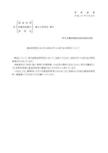
T-V Temperature Profile340TDUNOPReject Temperature, r280270Post T-Voper 2K/min(typ)260250MinOper24005101520253035Figure 5. Thermal-Vacuum Test ProfileTHERMODYNAMIC PERFORMANCEThe ABI cooler system has the capability to operate at an input power of 186 W for with aheat load of 1.9 - 2.3 W @ 53K for the linear cold head and a heat load between 5.1 W and 8.0W @ 183 K for the remote cold head; cooler reject temperature is defined to be 300K. The testresults, taken during the thermal-vacuum test profile, show a CCE input power of 162W for thespecified condition for cooler unit PFM-1; test results for cooler unit PFM-2 show a CCE inputpower of 170W for the specified condition. These data correspond to performance margins of14% and 11% respectively. Figure 6 shows the cooler load lines at load and no-load conditionsfor the two PFM coolers under test. For unit PFM-1, the slope for the linear cold head was 136mW/K and the remote cold head was 49 mW/K. For unit PFM-2, the slope for the linear coldhead was 137 mW/K and the remote cold head was 53 mW/K.Approved for public release; NG 08-0272, 4/3/08.
Load Line, 10-13-07, Sec 6.3.4.6; ATP: ANP-13A-002 Rev C; MSO: ANPAA01810; ABI FM1-1 Cooler #459380-1 s/n 303; CCE#408100-1 s/n 302; Acel Electroics #456007-1 s/n 9Linear Cold Block Applied Load (mW)25007000Corrected Power,InputpowerLoad: 154.24Watts 6000162 WCorrected Power,NO Load: 154.24 Watts2000500015004000300010002000500Linear Cold Block1000Remote Cold Block00204060801001201401601800200Cold Block Temperatures (K)PFM-1 Thermodynamic PerformanceLoad Line, 10-06-07, Thermo Dynamic Performance, 300K Reject, Sec 6.3.4.6; ATP: ANP-13A-002 Rev C; MSO: ANPAA01860;ABI FM1-2 Cooler #459380-2 s/n 302; CCE #D408100-1 s/n 301; Acel Electroics #456007-1 s/n 88000Applied Load Linear Cold Block (mW)2500Linear Cold BlockRemote Cold Block700020006000Input power 170 01601800200Cold Block Temperatures (K)PFM-2 Thermodynamic PerformanceFigure 6. ABI PFM Cooler Load LinesTEMPERATURE STABILTY PERFORMANCEThe ABI cooler has the capability to provide short term stability temperature control within100 mK peak-to-peak and long term stability within 500 mK. Temperature control stabilitydata was measured over a four (4) hour period in which the reject temperature was varied from260K to 298K at a rate of 0.16 K/min. Both PFM cooler systems demonstrated identical shortand long term stability within 60 mK peak-to-peak throughout this test. Test data from PFM-1,included as Figure 7, verifying this capability.Approved for public release; NG 08-0272, 4/3/08.
Ramp History, 10-25-07, Sec 8.4.10.9, 258 K to 300 K Reject;ATP: ANP-13A-002 Rev C; MSO: ANPAA01810;ABI FM1-1 Cooler #459380-1 s/n 303; CCE #408100-1 s/n 302; Acel Electronics #456007-1 s/n 954310PRT Cold Block - GSE53.6Comp Rej (K) D3300CCE Rej (K) D753.453.2290Short term limit0.1K p-p5328052.8Long term limit1.0K p-p52.652.4270Reject Temperature (K)Cold Block Temperature me (HH:MM)Figure 7. Temperature Control Stability, PFM-1SUMMARYThe ABI protoflight module coolers developed by Northrop Grumman have successfullyverified cooler system operation. Survivability and operability performance have beendemonstrated through applied launch vibration and thermal-vacuum test profiles.Thermodynamic performance has been validated with demonstrated performance margin of 11 to14%; temperature control stability performance is handily met.These coolers have been delivered to ITT for system level integration and furtherverification of higher level system performance. Remaining flight modules are planned forcompletion of acceptance testing and delivery in CY 2008.Approved for public release; NG 08-0272, 4/3/08.
The ABI cooler system has the capability to operate at an input power of 186 W for with a heat load of 1.9 - 2.3 W @ 53K for the linear cold head and a heat load between 5.1 W and 8.0 W @ 183 K for the remote cold head; cooler reject temperature is defined to be 300K. The test results, taken during the thermal-vacuum test profile, show a CCE input power of 162W for the specified .