Transcription
Instructions for thefollowing series products:Full Body Harnesses(See back pages for specificmodel numbers.)USER INSTRUCTION MANUALFULL BODY HARNESSThis manual is intended to meet the Manufacturer’s Instructionsas required by ANSIZ359 and CSA 259.10 and should be used aspart of an employee training program as required by OSHAForm: 5908231Rev: M Copyright 2009, DB Industries, Inc.
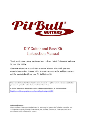
Figure 1 - Delta Vest Full Body HarnessShoulder Strap(inside vest)Chest StrapAttachmentElement forFall Arrest(D-ring orWeb Loop)Leg StrapLabels andRFID Tag(inside vest)3
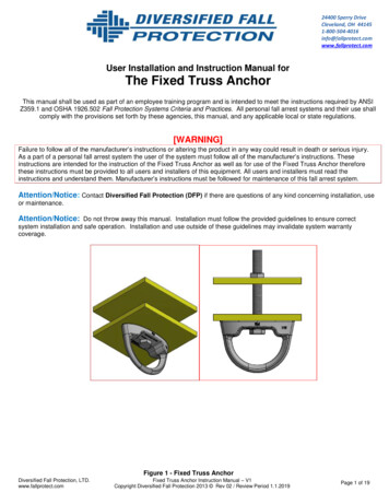
Figure 2 - Vest Style Full Body HarnessShoulder StrapChest StrapLeg StrapAttachmentElement forFall Arrest(D-ring orWeb Loop)D-ring PadLabels andRFID Tag4
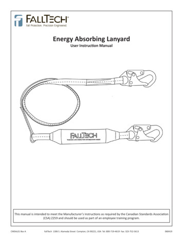
Figure 3 - Cross-over Style Full Body HarnessShoulder StrapFront Attachment Element(D-ring or Web Loop)Leg StrapAttachmentElement forFall Arrest(D-ring orWeb Loop)D-ring PadLabels andRFID Tag5
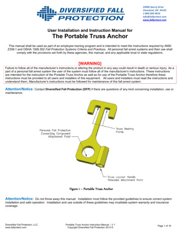
Figure 4 - Step-in Style Full Body HarnessShoulder StrapFront D-ringLeg StrapAttachmentElement forFall Arrest(D-ring orWeb Loop)D-ring PadLabels andRFID Tag6
WARNING: This product is part of a personal fall arrest, restraint,work positioning, personnel riding, climbing, or rescue system. Theuser must follow the manufacturer’s instructions for each componentof the system. These instructions must be provided to the user of thisequipment. The user must read and understand these instructionsbefore using this equipment. Manufacturer’s instructions must befollowed for proper use and maintenance of this equipment. Alterationsor misuse of this product or failure to follow instructions may result inserious injury or death.IMPORTANT: If you have questions on the use, care, or suitability ofthis equipment for your application, contact DBI-SALA.IMPORTANT: Before using this equipment, record the productidentification information from the ID label in the inspection andmaintenance log in section 9.0 of this manual.DESCRIPTIONSDelta Vest Full Body Harness: See Figure 1.Vest Style Full Body Harness: See Figure 2.Cross-Over Style Full Body Harness: See Figure 3.Step-In Style Full Body Harness: See Figure 4.OPTIONS:DBI-SALA Full Body Harnesses are available with options andaccessories. Following is a partial list of commonly used optionsand accessories (some options may not be available on allharnesses): Shoulder D-ringsSide D-ringsHip pad with side D-ringsQuick Connect bucklesTongue buckle body beltLoops on harness for body beltKevlar webbingHigh visibility webbingNon-sparking/Non conductive PVC coated hardwareShoulder padsTool belt support strapsSeat slingLanyard attached directly to D-ring or attachment elementSnap fastener on shoulder strap for retaining lanyardDelta Vest Tool holders7
1.01.1APPLICATIONSPURPOSE: DBI-SALA full body harnesses are to be used ascomponents in personal fall arrest, restraint, work positioning, orrescue systems. See Figures 1, 2, 3, and 4 for harness styles.Harnesses included in this manual are full body harnesses andmeet ANSI Z359.1, OSHA, and CSA Z259.10 requirements. SeeFigure 5 for application illustrations. Full body harnesses with Kevlar web should be used whenworking with tools, materials, or environments of hightemperature (foundries, chemical manufacturing, steelfabrication, emergency rescue services, fire services, welders,oil industry, nuclear industry, explosives).Harnesses with PVC coated hardware should be used whenworking in explosive or electrically conductive environments, orwhere surfaces must be protected from the hardware.Harnesses with high visibility webbing should be used whenincreased visibility of the user is required.A.PERSONAL FALL ARREST: The full body harnessis used as a component of a personal fall arrestsystem. Personal fall arrest systems typicallyinclude a full body harness and a connectingsubsystem (energy absorbing lanyard). Maximumarresting force must not exceed 1,800 lbs (8kN).For fall protection applications connect thefall arrest subsystem (example: lanyard, SRL,energy absorber, etc.) to the D-ring or attachmentelement on your back, between your shoulderblades.B.WORK POSITIONING: The full body harnessis used as a component of a work positioningsystem to support the user at a work position.Work positioning systems typically include a fullbody harness, positioning lanyard, and a back-uppersonal fall arrest system. For work positioningapplications, connect the work positioningsubsystem (example: lanyard, Y-lanyard, etc.)to the lower (hip level) side or belt mountedwork positioning attachment anchorage elements(D-rings). Never use these connection points forfall arrest.8
Figure 5 - ApplicationsAnchorageAnchorage ConnectorAnchorageAnchorage ConnectorConnecting Subsystem(Self Retracting LifelineShown)Full Body HarnessFull Body HarnessRestraintFall ArrestAnchorageLadderAnchorageConnectorCable SleeveBack-up FallArrest SystemRestraint LanyardFull BodyHarnessRestraint LanyardAnchorageCross-overFull BodyHarnessCableAnchorageConnectorWork PositioningLadder ClimbingC.LADDER CLIMBING: The full body harnessis used as a component of a climbing systemto prevent the user from falling when climbinga ladder or other climbing structure. Climbingsystems typically include a full body harness,vertical cable or rail attached to the structure, andclimbing sleeve.For ladder climbing applications,harnesses equipped with a frontal D-ring in thesternal location may be used for fall arrest onfixed ladder climbing systems. These are definedin Z259.2.1 in Canada and ANSI A14.3 in theUnited States.D.RESCUE: The full body harness is used as acomponent of a rescue system. Rescue systemsare configured depending on the type of rescue.For limited access (confined space) applications,harnesses equipped with D-rings on the shouldersmay be used for entry and egress into confinedspaces where worker profile is an issue.9
1.2E.CONTROLLED DESCENT: For controlled descentapplications, harnesses equipped with a singlesternal level D-ring, one or two frontal mountedD-rings, or a pair of connectors originating belowthe waist (such as a seat sling) may be used forconnection to a descender or evacuation system(reference in Z259.10 in Canada).F.RESTRAINT: The full body harness is used as a componentof a restraint system to prevent the user from reaching a fallhazard. Restraint systems typically include a full body harnessand a lanyard or restraint line.LIMITATIONS: Consider the following application limitationsbefore using this equipment:A. CAPACITY: These full body harnesses are designed for useby persons with a combined weight (clothing, tools, etc.) of nomore than 420 lbs. Make sure all of the components in yoursystem are rated to a capacity appropriate to your applicationB. FREE FALL: Personal fall arrest systems used with thisequipment must be rigged to limit the free fall to 6 feet (1.8M) (ANSI Z359.1). Restraint systems must be rigged so thatno vertical free fall is possible. Work positioning systems mustbe rigged so that free fall is limited to 2 feet (.6 m) or less.Personnel riding systems must be rigged so that no verticalfree fall is possible. Climbing systems must be rigged so thatfree fall is limited to 18 in. (.46 cm) or less. Rescue systemsmust be rigged so that no vertical free fall is possible. Seesubsystem manufacturer’s instructions for more information.C. FALL CLEARANCE: See Figure 6. There must be sufficientclearance below the user to arrest a fall before the user strikesthe ground or other obstruction. The clearance required isdependent on the following factors: Elevation of anchorageConnecting subsystem lengthDeceleration distanceFree fall distanceWorker heightMovement of harness attachment elementSee subsystem manufacturer’s instructions for more information.10
Figure 6 - Fall ClearanceFigure 7 - Swing FallConnecting Subsystem(Energy Absorbing Lanyardshown)Free Fall6 ft. max(ANSI Z359.1)Total Fall Distance(Free Fall Deceleration)Working LevelDecelerationDistanceSwingFallHazardNOTE: When calculatingfall clearance, anadditional 6 in. (15.3cm) should be includedto allow for expectedharness stretch.Lower Level or ObstructionD. SWING FALLS: See Figure 7. Swing falls occur when theanchorage point is not directly above the point where a falloccurs. The force of striking an object in a swing fall maycause serious injury or death. Minimize swing falls by workingas close to the anchorage point as possible. Do not permita swing fall if injury could occur. Swing falls will significantlyincrease the clearance required when a self- retracting lifeline orother variable length connecting subsystem is used.E. EXTENDED SUSPENSION: A full body harness is notintended for use in extended suspension applications. If theuser is going to be suspended for an extended length of timeit is recommended that some form of seat support be used.DBI-SALA recommends a seat board, suspension workseat,seat sling, or a boatswain chair. Contact DBI-SALA for moreinformation on these items.F. ENVIRONMENTAL HAZARDS: Use of this equipment in areaswith environmental hazards may require additional precautionsto prevent injury to the user or damage to the equipment.Hazards may include, but are not limited to; heat, chemicals,corrosive environments, high voltage power lines, gases,moving machinery, and sharp edges.G. HARNESSES FOR HIGH TEMPERATURE ENVIRONMENTS:Harnesses with Kevlar webbing are designed for use in hightemperature environments, with limitations: Kevlar webbingbegins to char at 800 to 900 Fahrenheit. Kevlar webbingcan withstand limited contact exposure to temperatures up to1,000 F. Polyester webbing loses strength at 300 to 400 F.PVC coating on hardware has a melting point of approximately350 F.11
IMPORTANT: When working with tools, materials, or in hightemperature environments, ensure that associated fall protectionequipment can withstand high temperatures, or provide protection forthose items.IMPORTANT: Although PVC coated, cadmium, or zinc plated hardwareexhibit excellent corrosion resistance in chemical, acidic, alkaline, andatmospheric conditions, frequent inspections may be required. Consultwith DBI-SALA if you question the use of this equipment in hazardousenvironments.H. TRAINING: This equipment must be installed and used bypersons trained in its correct application and use. See section4.0.1.3APPLICABLE STANDARDS: Refer to national standards, includingANSI Z359 (.0, .1, .2, .3, and .4) family of standards on fallprotection, ANSI A10.32, CSA Z259.10, and applicable local, stateand federal (OSHA) requirements governing occupational safety formore information about work positioning systems.IMPORTANT: Harnesses with Kevlar webbing do not meet ANSIZ359.1. Kevlar does not have equivalent abrasion resistance ofpolyamides. Kevlar harnesses meet all other requirements of thisstandard.2.0SYSTEM REQUIREMENTS2.1COMPATIBILITY OF COMPONENTS: DBI-SALA equipmentis designed for use with DBI-SALA approved components andsubsystems only. Substitutions or replacements made with nonapproved components or subsystems may jeopardize compatibilityof equipment and may effect the safety and reliability of thecomplete system.2.2COMPATIBILITY OF CONNECTORS: Connectors are consideredto be compatible with connecting elements when they have beendesigned to work together in such a way that their sizes andshapes do not cause their gate mechanisms to inadvertently openregardless of how they become oriented. Contact DBI-SALA if youhave any questions about compatibility.Connectors (hooks, carabiners, and D-rings) must be capableof supporting at least 5,000 lbs. (22.2 kN). Connectors must becompatible with the anchorage or other system components.Do not use equipment that is not compatible. Non-compatibleconnectors may unintentionally disengage. See Figure 8.Connectors must be compatible in size, shape, and strength. Selflocking snap hooks and carabiners are required by ANSI Z359.1and OSHA.12
2.3 MAKING CONNECTIONS: Use only self-locking snap hooks andcarabiners with this equipment. Use only connectors that aresuitable to each application. Ensure all connections are compatiblein size, shape and strength. Do not use equipment that is notcompatible. Ensure all connectors are fully closed and locked.DBI-SALA connectors (snap hooks and carabiners) are designed tobe used only as specified in each product’s user’s instructions. SeeFigure 9 for inappropriate connections. DBI-SALA snap hooks andcarabiners should not be connected:A. To a D-ring to which another connector is attached.B. In a manner that would result in a load on the gate.Figure 8 - Unintentional Disengagement (Rollout)If the connecting element to which a snap hook (shown) or carabinerattaches is undersized or irregular in shape, a situation could occurwhere the connecting element applies a force to the gate of the snaphook or carabiner. This force may cause the gate (of either a selflocking or a non-locking snap hook) to open, allowing the snap hook orcarabiner to disengage from the connecting point.Small ring orother noncompatiblyshaped element1.FORCE IS APPLIED TOTHE SNAP HOOK.2. THE GATE PRESSESAGAINST THECONNECTING RING3. THE GATE OPENSALLOWING THESNAP HOOK TOSLIP OFFNOTE: Large throat snap hooks should not be connected to standardsize D-rings or similar objects which will result in a load on the gateif the hook or D-ring twists or rotates, unless the snap hook complieswith ANSI Z359.1-2007 and is equipped with a 3,600 lb gate. Checkthe marking on your snap hook to verify that it is appropriate for yourapplication.C. In a false engagement, where features that protrude from thesnap hook or carabiner catch on the anchor, and without visualconfirmation seems to be fully engaged to the anchor point.13
Figure 9 - Inappropriate ConnectionsD. To each other.E. Directly to webbing or rope lanyard or tie-back (unless themanufacturer’s instructions for both the lanyard and connectorspecifically allows such a connection).F. To any object which is shaped or dimensioned such that thesnap hook or carabiner will not close and lock, or that roll-outcould occur.2.4CONNECTING SUBSYSTEMS: Connecting subsystems (selfretracting lifeline, lanyard, rope grab and lifeline, cable sleeve)must be suitable for your application. See section 1.1. Seesubsystem manufacturer’s instructions for more information. Someharness models have web loop connection points. Do not usesnap hooks to connect to web loops. Use a self-locking carabinerto connect to a web loop. Ensure the carabiner cannot cross-gateload (load against the gate rather than along the backbone of thecarabiner). Some lanyards are designed to choke onto a web loopto provide a compatible connection. See Figure 10. Lanyards maybe sewn directly to the web loop forming a permanent connection.Do not make multiple connections onto one web loop, unlesschoking two lanyards onto a properly sized web loop.2.5ANCHORAGE STRENGTH: The anchorage strength requiredis dependent on the application type. The following are therequirements of ANSI 359.1 for these application types:A.FALL ARREST: Anchorages selected for fall arrest systemsshall have a strength capable of sustaining static loads appliedin the directions permitted by the system of at least:1. 5,000 lbs. (22.2 kN) for non-certified anchorages, or2. Two times the maximum arresting force for certifiedanchorages. When more than one fall arrest system is14
attached to ananchorage, thestrengths setforth in (1) and(2) above shallbe multipliedby the numberof systemsattached to theanchorage.Figure 10 - Web Loop ConnectionInsert lanyard web loop throughweb loop or D-ring on harnessHarness Web Loopor D-ringWeb Loop onEnergy Absorbing LanyardB. RESTRAINT:AnchoragesInsert appropriate end of lanyardselected forthrough the lanyard web looprestraint andtravel restraintsystems shallhave a strengthcapable ofPull the lanyard through theconnecting web loop to securesustainingstatic loadsapplied in thedirections permitted by the system of at least:1. 1,000 lbs. (4.5 kN) for non-certified anchorages, or2. Two times the foreseeable force for certified anchorages.When more than one restraint and travel restraint systemis attached to an anchorage, the strengths set forth in (1)and (2) above shall be multiplied by the number of systemsattached to the anchorage.C.WORKING POSITIONING: Anchorages selected for workpositioning systems shall have a strength capable of sustainingstatic loads applied in the directions permitted by the systemof at least:1. 3,000 lbs. (13.3 kN) for non-certified anchorages, or2. Two times the foreseeable force for certified anchorages. Whenmore than one work positioning system is attached to an anchorage,the strengths set forth in (1) and (2) above shall be multiplied by thenumber of systems attached to the anchorage.D.RESCUE: Anchorages selected for rescue systems shall have astrength capable of sustaining static loads applied in the directionspermitted by the system of at least:1. 3,000 lbs. (13.3 kN) for non-certified anchorages, or2. Five times the foreseeable force for certified anchorages. Whenmore than one rescue system is attached to an anchorage, thestrengths set forth in (1) and (2) above shall be multiplied by thenumber of systems attached to the anchorage.E. CLIMBING: The structure to which a climbing system is attachedmust sustain the loads required by that particular system. Seeinstructions for climbing system for requirements.15
3.0 DONNING AND USEWARNING: Do not alter or intentionally misuse this equipment. ConsultDBI-SALA when using this equipment in combination with components orsubsystems other than those described in this manual. Some subsystemand component combinations may interfere with the operation of thisequipment. Use caution when using this equipment around movingmachinery, electrical and chemical hazards, and sharp edges.WARNING: Consult your doctor if there is reason to doubt yourfitness to safely absorb the shock from a fall arrest. Age and fitnessseriously affect a worker’s ability to withstand falls. Pregnant womenor minors must not use any DBI-SALA full body harness.3.1BEFORE EACH USE of this equipment inspect it according tosection 5.0 of this manual.3.2PLAN your system before use. Consider all factors that will affectyour safety during use of this equipment. The following list givesimportant points to consider when planning your system:A. ANCHORAGE: Select an anchorage that meets therequirements specified in sections 1.2 and 2.5.B. SHARP EDGES: Avoid working where system componentsmay be in contact with, or abrade against, unprotected sharpedges.C. AFTER A FALL: Components which have been subjected tothe forces of arresting a fall must be removed from service anddestroyed.D. RESCUE: The employer must have a rescue plan when usingthis equipment. The employer must have the ability to performa rescue quickly and safely.16
3.3DONNING AND FITTING THE HARNESS:A. DELTA VEST HARNESS: See Figure 11 for front and backviews of the Delta Vest harness. Don the Delta Vest fullbody harness by following these steps (see Figures 12 and 13).Figure 11 - Front and Back View of Delta Vest HarnessStep 1.Lift harness by the back D-ring and untangle straps.Allow leg straps to hang free.Step 2.Don the Vest Harness as you would a jacket. Do not zipthe vest at this time.Step 3.Connect chest strap by passing male buckle throughfemale buckle. Pass excess webbing through loopkeepers. See Figure 13.Step 4.Reach between legs and grasp blue leg strap on yourleft side. Bring strap up between legs and connect tobuckle attached to yellow strap (orange on high visibilitymodels, black on flame resistant models) as shown inFigures 12 and 13. Connect right leg strap.Step 5.Reach inside the vest and adjust shoulder straps toa snug fit. Left and right shoulder straps should beadjusted to the same length. Readjust leg straps, cheststrap, and shoulder straps as necessary to a snug fit.Step 6.Zip the vest.17
Figure 12 - Donning the Delta Vest HarnessDelta Vest HarnessStep 1Step 2Step 3Step 4Step 5Step 618
Figure 13 - Delta Vest Harness Buckle ConnectionsChest Strap: Pass male bucklethrough female buckle and pull freeend of webbing to tighten.Tongue Buckle: Pass webbingthrough buckle and insert tonguethrough grommet.Parachute Buckle: Pass webbingunder buckle and over roller anddown between roller and frame.Pull web end to tighten. Threeinches of web must extend pastbuckle.Pass Buckle: Pass male bucklethrough female buckle and pull freeend of webbing to tighten.B. VEST STYLEFigure 14 - Removable Waist BeltHARNESS: If your& Hip Padharness incorporatesloops for a removablewaist belt, the beltshould be installedthrough the four loopsin the harness as shownin Figure 14. The hippad, if used, is securedto the belt by passingthe belt through the hippad loops. Don the veststyle full body harnessby following these steps(see Figures 15 and16):Step 1.Locate back D-ring held in position by the D-ring pad;lift up harness and hold by this D-ring. Ensure the strapsare not twisted.Step 2.Grasp the shoulder straps and slip harness onto onearm. D-ring will be located on your back side. Ensure19
Figure 15 - Donning Vest Style HarnessStep 1Step 2Step 3Step 4Step 520
Figure 16 - Vest Style Harness Buckle ConnectionsChest Strap: Attach chest strap byinserting the tab of the buckle intothe receptor of the quick connectbuckle until a click is heard.Chest Strap: Pass male bucklethrough female buckle and pull freeend of webbing to tighten.Parachute Buckle: Pass webbingunder buckle and over roller anddown between roller and frame.Pull web end to tighten. Threeinches of web must extend pastbuckle.Tongue Buckle: Pass webbingthrough buckle and insert tonguethrough grommet.Pass Buckle: Pass male bucklethrough female buckle and pull freeend of webbing to tighten.Quick Connect Buckle: Insert thetab of the buckle into the receptor ofthe quick connect buckle until a clickis heard.straps are not tangled and hang freely. Slip free arm intoharness and position shoulder straps on top of shoulder.Ensure straps are not tangled and hang freely. Cheststrap with pass through buckle will be positioned on frontside when worn properly.Step 3.Reach between your legs and grasp the leg strap onyour left side. Bring the strap up between your legsand connect it by inserting the tab of the buckle intothe receptor of quick connect buckle on the left side asshown in Figure 1. You will hear a click when the tabengages properly. Pull the free end of the strap away21
from the buckle to make a snug fit on each leg strap. Toloosen the leg strap, grasp the yellow plastic portion ofthe buckle and pull away from your leg to allow the strapto pull through the buckle. A plastic end keeper on theend of the strap will stop it from pulling completely outof the buckle. To release the buckle, press the silvercolored tabs on the buckle towards each other with onehand, while pulling on the tab portion to the buckle withthe other hand. Repeat this procedure for the right side.Step 4.Attach the chest strap by inserting the tab of the buckleinto receptor of quick connect buckle. See Figure 1.You will hear a click when the tab engages properly.Chest strap should be six inches down from the top ofshoulders. Pass excess strap through the loop keepers.The strap may be tightened to a snug fit by pulling thefree strap end to the left (away from the buckle). Toloosen the chest strap, grasp the yellow plastic portionof the buckle and pull away from the body to allow thestrap to pull through the buckle. A plastic end keeper onthe end of the strap will stop it from pulling completelyout of the buckle. To release the buckle, press the silvercolored tabs on the buckle towards each other with onehand, while pulling on the tab portion to the buckle withthe other hand.Step 5.Adjust shoulder straps to a snug fit by pulling excessstrap through the parachute buckles on each side of theharness. Left and right sides of shoulder straps shouldbe adjusted to the same length and the chest strapshould be centered on your lower chest, six inches downfrom shoulder. The front D-ring on vest style harnessis moved up or down by adjusting the shoulder strapsand leg straps.Figure 17 - Removable Waist BeltCenter the backand Hip PadD-ring betweenshoulder blades.Adjust leg strapsto a snug fit. Atleast three inchesof webbing mustextend pastbuckle on legstraps. Adjustthe waist belt (ifpresent).C. CROSS-OVER STYLEHARNESS: If yourharness incorporatesloops for a removablewaist belt, the belt22
Figure 18 - Donning Cross-over Style HarnessStep 2Step 1Step 3Step 4Step 523
should be installed through the four loops in the harness asshown in Figure 17. The hip pad, if used, is secured to thebelt by passing the belt through the hip pad loops. Don thecross-over style full body harness by following these steps (seeFigures 18 and 19):Step 1.Locate back D-ring held in position by the D-ring pad;lift up harness and hold by this D-ring. Ensure the strapsare not twisted.Step 2.Grasp shoulder straps between back and front D-ring andslip harness over your head from the left side. Positionshoulder straps on top of shoulder. Ensure straps are nottangled and hang freely. The D-ring will be positioned onyour back when worn properly.Step 3.Grasp male pass-through buckle located on yellowstrap (orange on high visibility models, black on flameresistant models) below front D-ring and connect tofemale pass-through buckle (attached to blue or strap onright hip). Male end of buckle must pass through femaleend. Ensure straps are not tangled or crossed.Step 4.Reach between legs and grasp blue leg strap on yourFigure 19 - Cross-over Style Harness Buckle ConnectionsTongue Buckle: Pass webbingthrough buckle and insert tonguethrough grommet.Pass Buckle: Pass male bucklethrough female buckle and pull freeend of webbing to tighten.Parachute Buckle: Pass webbingunder buckle and over roller anddown between roller and frame.Pull web end to tighten. Threeinches of web must extend pastbuckle.Quick Connect Buckle: Insert thetab of the buckle into the receptor ofthe quick connect buckle until a clickis heard24
left side. Bring strap up between legs and connect tobuckle attached to yellow strap (orange on high visibilitymodels, black on flame resistant models). Connect rightleg strap.Step 5.Adjust shoulder straps to a snug fit. Left and right sidesof shoulder straps should be adjusted to the same lengthand the front D-ring should be centered on your lowerchest. The back D-ring should be centered between yourshoulder blades. Adjust leg straps to a snug fit. At leastthree inches of webbing must extend past parachuteadjuster buckle when used on leg straps. Adjust thewaist belt (if present). Center retrieval D-rings (ifpresent) on top of each shoulder.D. STEP-IN STYLE HARNESS: Don the step-in style full bodyharness by following these steps (see Figures 20 and 21):3.4Step 1.Locate back D-ring held in position by the D-ring pad;lift up harness and hold by this D-ring. Ensure the strapsare not twisted.Step 2.Step into harness by placing right leg over the seat slingand then your left leg.Step 3.Raise harness up and slip arms between front and backshoulder straps. Slip the back D-ring pad over your headwith your head between the front shoulder straps andthe adjuster links.Step 4.Reach between legs and grasp blue leg strap on yourleft side. Bring strap up between legs and connect tobuckle attached to yellow strap (orange on high visibilitymodels, black on flame resistant models). Connect rightleg strap.Step 5.Tighten shoulder straps through adjuster links and frontD-ring. Adjustment slack should be given out or takenup through the buckle on the lower left shoulder strap.Left and right shoulder straps should be adjusted to thesame length, and the front D-ring should be centered onyour lower chest. The back D-ring should be centeredbetween your shoulder blades. Adjust leg straps to asnug fight.USE OF FALL ARREST D-RING OR ATTACHMENT ELEMENT:For fall protection applications connect to the D-ring or attachmentelement on your back, between your shoulder blades. SideD-rings, if present, are for positioning or restraint applications only.Shoulder retrieval D-rings are for rescue or retrieval applicationsonly. Front D-ring is for ladder climbing or positioning. D-rings onseat sling are for suspension or positioning applications only.25
Figure 20 - Donning Step-in Style HarnessStep 2Step 1Step 3Step 5Step 426
Figure 21 - Step-in Style Harness Buckle ConnectionsPass Buckle: Pass male bucklethrough female buckle and pull freeend of webbing to tighten.Tongue Buckle: Pass webbingthrough buckle and insert tonguethrough grommet.Parachute Buckle: Pass webbingunder buckle and over roller anddown between roller and frame. Pullweb end to tighten. Three inches ofweb must extend past buckle.3.5MAKING CONNECTIONS: When using a hook to connect to ananchorage or when coupling components of the system together,ensure roll-out cannot occur. Roll-out occurs when interferencebetween the hook and mating connector causes the hook gateto unintentionally open and release. Self-locking snap hooks andcarabiners should be used to reduce the possibility of roll-out. Donot use hooks or connectors that will not completely close over theattachment object. See subsystem manufacturer’s instructions formore information on making connections.3.6CONNECTING SYSTEM COMPONENTS: After fitting the full bodyharness the user may then connect to other system components.Follow the guidelines in section 3.4 on selecting the correctattachment element.4.04.1TRAININGIt is the responsibility of the user and the purchaser of thisequipment to assure that they are familiar with these instructions,trained in the correct care and use of, and are aware of theoperating characteristics, application limits, and the consequencesof improper use of this equipment.IMPORTANT: Training must be conducted without exposing the userto a
components in personal fall arrest, restraint, work positioning, or rescue systems. See Figures 1, 2, 3, and 4 for harness styles. Harnesses included in this manual are full body harnesses and meet ANSI Z359.1, OSHA, and CSA Z259.10 requirements. See Figure 5 for application illustrations.