Transcription
Data Center E-BookDeploying, Managing and Securing an Efficient Physical Infrastructurewww.siemon.com1
Table of Contents10GBASE-T for Broad 10Gigabit Adoption in the Data Center.4Considerations for Overall SLAʼs for Co-location and Cloud Facility Owners and Hosting Providers.12Data Centers Strategies and Considerations for Co-Location and Cloud Tenants .19Data Centers - Point to Point vs. Structured Cabling .25Data Center Cooling Best Practices.33Intelligence at the Physical Layer .44Appendix.483www.siemon.com
10GBASE-T10GBase-T for Broad 10Gigabit Adoption in the Data CenterContributors:Carl G. Hansen, IntelCarrie Higbie, Siemonwww.siemon.com4
10 Gigabit Ethernet: Drivers for AdoptionThe growing use of virtualization in data centers to address the need to reduce IT costs has caused manyadministrators to take a serious look at 10Gb Ethernet (10GbE) as a way to reduce the complexities they facewhen using the existing 1Gb Ethernet (1GbE) infrastructures. The server consolidation associated with virtualization has had significant impact on network I/O because they combine the network needs of severalphysical machines and the other background services, such as live migration, over the Ethernet network ontoa single machine.Together with trends such as unified networking, the ability to use a single Ethernet network for both data andstorage traffic, are increasing I/O demands to the point where a 1GbE network can be a bottleneck and asource of complexity in the data center. The move to implement unified networking requires rethinking of datacenter networks. While 1GbE connections might be able to handle the bandwidth requirements of a single traffic type, they do not have adequate bandwidth for multiple traffic types during peak periods. This creates a needfor multiple 1GbE connections.Moving to 10 Gigabit Ethernet (10GbE) addresses these network problems by providing more bandwidth andsimplifies the network infrastructure by consolidating multiple gigabit ports into a single 10 gigabit connection.Data Center Administrators have a number of 10GbE interfaces to choose from including CX4, SFP Fiber, SFP Direct Attach Copper (DAC), and 10GBASE-T. Today, most are choosing either 10GbE Optical or SFP DAC.However, limitations with each of these interfaces have kept them from being broadly deployed across thedata center.Fiber connections are not cost-effective for broad deployment, and SFP DAC is limited by its seven meterreach, and requires a complete infrastructure upgrade. CX4 is an older technology that does not meet highdensity requirements. For 10GBASE-T, the perception to date has been that it required too much power andwas too costly for broad deployments. These concerns are being addressed with the latest manufacturingprocesses that are significantly reducing both the power and the cost of 10GBASE-T.Widespread deployment requires a cost-effective solution that is backward compatible and has the flexibilitycapable of reaching the majority of switches and servers in the data center. This white paper looks at what isdriving choices for deploying 10GbE and how 10GBASE-T will lead to broader deployment, including its integration into server motherboards. It also outlines the advantages of 10GBASE-T in the data center, includingimproved bandwidth, greater flexibility, and infrastructure simplification, ease of migration, and cost reduction.5www.siemon.com
The Need for 10 Gigabit EthernetA variety of technological advancements and trends are driving the increasing need for 10GbE in the data center.For instance, the widespread availability of multi-core processors and multi-socket platforms is boosting serverperformance. That performance allows customers to host more applications on a single server resulting in multipleapplications competing for a finite number of I/O resources on the server. Customers are also using virtualization toconsolidate multiple servers onto a single physical server, reducing their equipment and power costs. Servers usingthe latest Intel Xeon processors can support server consolidation ratios of up to fifteen to one .However, server consolidation and virtualization have a significant impact on a server’s network bandwidthrequirements, as the I/O needs of several servers now need to be met by a single physical server’s network resources. To match the increase in network I/O demand, IT has scaled their network by doubling, tripling, or evenquadrupling the number of gigabit Ethernet connections per server. This model has led to increased networkingcomplexity, as it requires additional Ethernet adapters, network cables and switch ports.The transition to unified networking adds to the increasing demand for high bandwidth networking. IT departmentsare moving to unified networking to help simplify network infrastructure by converging LAN and SAN traffic,including iSCSI, NAS, and FCoE for a single Ethernet data center protocol. This convergence does simplify the network but significantly increases network I/O demand by enabling multiple traffic types to share a single Ethernet fabric.Continuing down the GbE path is not sustainable, as the added complexity, power demands, and cost of additionalGbE adapters will not allow customers to scale to meet current and future I/O demands. Simply put, scaling GbEto meet these demands significantly increases the cost and complexity of the network. Moving to 10GbE addressesthe increased bandwidth needs while greatly simplifying the network and lowering power consumption byreplacing multiple gigabit connections with a single or dual port 10GbE connection.1 Source: Results have been estimated based on internal Intel analysis and are provided for informational purposes only. Any difference in system hardware or software design or configuration may affect actual performance.www.siemon.com6
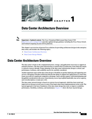
Media Options for 10 Gigabit EthernetDespite industry consensus regarding the move to 10GbE, the broad deployment of 10GbE has been limited,due to a number of factors. Understanding this dynamic requires an examination at the pros and cons of current10GbE media options.10GbE Media OptionsThe challenge IT managers face with 10GbE currently is that each of the current options has a downside, whetherin terms of cost, power consumption, or reach.7www.siemon.com
10GBASE-CX410GBASE-CX4 was an early favorite for 10GbE deployments, however its adoption was limited by the bulky andexpensive cables, and its reach is limited to 15 meters. The size of the CX4 connector prohibited higher switchdensities required for large scale deployment. Larger diameter cables are purchased in fixed lengths resultingin challenges to manage cable slack. Pathways and spaces may not be sufficient to handle the larger cables.SFP SFP ’s support for both fiber optic cables and DAC make it a better (more flexible) solution than CX4. SFP isramping today, but has limitations that will prevent this media from moving to every server.10GBASE-SR (SFP Fiber)Fiber is great for latency and distance (up to 300 meters), but it is expensive. Fiber offers low powerconsumption, but the cost of laying fiber networking everywhere in the data center is prohibitive duelargely to the cost of the electronics. The fiber electronics can be 4-5 times more expensive than theircopper counterparts meaning that ongoing active maintenance, typically based on original equipmentpurchase price, is also more expensive. Where a copper connection is readily available in a server,moving to fiber creates the need to purchase not only the fiber switch port, but also a fiber NIC forthe server.10GBASE-SFP DACDAC is a lower cost alternative to fiber, but it can only reach 7 meters and it is not backward compatible with existing GbE switches. DAC requires the purchase of an adapter card and requires a newtop of rack (ToR) switch topology. The cables are much more expensive than structured copper channels, and cannot be field terminated. This makes DAC a more expensive alternative to 10GBASE-T.The adoption of DAC for LOM will be low since it does not have the flexibility and reach of BASE-T.10GBASE-T10GBASE-T offers the most flexibility, is the lowest cost media type, and is backward compatible with existing1GbE networks.REACHLike all BASE-T implementations, 10GBASE-T works for lengths up to 100 meters, giving IT managersa far-greater level of flexibility in connecting devices in the data center. With flexibility in reach,10GBASE-T can accommodate either top of the rack, middle of row, or end of the row networktopologies. This gives IT managers the most flexibility in server placement since it will work with existing structured cabling systems.For higher grade cabling plants (category 6A and above) 10GBASE-T operates in low power mode (also knownas data center mode) on channels under 30m. This equates to a further power savings per port over the longer100m mode. Data centers can create any-to-all patching zones to assure less than 30m channels to realize thissavings.www.siemon.com8
Backward CompatibilityBecause 10GBASE-T is backward-compatible with 1000BASE-T, it can be deployed in existing 1GbE switch infrastructures in data centers that are cabled with CAT6, CAT6A or above cabling, allowing IT to keep costs down while offering an easy migration path to 10GbE.PowerThe challenge with 10GBASE-T is that the early physical layer interface chips (PHYs) have consumed too much powerfor widespread adoption. The same was true when gigabit Ethernet products were released. The original gigabit chipswere roughly 6.5 Watts/ port. With process improvements, chips improved from one generation to the next. The resulting GbE ports are now under 1W / port. The same has proven true for 10GBASE-T. The good news with 10GBASET is that these PHYs benefit greatly from the latest manufacturing processes. PHYs are Moore’s Law friendly, and thenewer process technologies will continue to reduce both the power and cost of the latest 10GBASE-T PHYs.When 10GBASE-T adapters were first introduced in 2008, they required 25w of power for a single port. Power hasbeen reduced in successive generations of using newer and smaller process technologies. The latest 10GBASE-T adaptersrequire only 10w per port. Further improvements will reduce power even more. By 2011, power will drop below 5watts per port making 10GBASE-T suitable for motherboard integration and high density switches.LatencyDepending on packet size, latency for 1000BASE-T ranges from sub-microsecond to over 12 microseconds. 10GBASET ranges from just over 2 microseconds to less than 4 microseconds, a much narrower latency range.For Ethernet packet sizes of 512B or larger, 10GBASE-T’s overall throughout offers an advantage over 1000BASE-T.Latency for 10GBASE-T is more than 3 times lower than 1000BASE-T at larger packet sizes. Only the most latentsensitive applications such as HPC or high frequency trading systems would notice any latency.The incremental 2 microsecond latency of 10GBASE-T is of no consequence to most users. For the large majority of enterprise applications that have been operating for years with 1000BASE-T latency, 10GBASE-T latency only gets better.Many LAN products purposely add small amounts of latency to reduce power consumption or CPU overhead. A common LAN feature is interrupt moderation. Enabled by default, this feature typically adds 100 microseconds of latencyin order to allow interrupts to be coalesced and greatly reduce the CPU burden. For many users this trade-off providesan overall positive benefit.CostAs power metrics have dropped dramatically over the last three generations, cost has followed a similar downwardcurve. First-generation 10GBASE-T adapters cost 1000 per port. Today’s third-generation dual-port 10GBASE-Tadapters are less than 400 per port. In 2011, 10GBASE-T will be designed as LAN on Motherboard (LOM) and willbe included in the price of the server. By utilizing the new resident 10GBASE-T LOM modules, users will see a significant savings over the purchase price of more expensive SFP DAC and fiber optic adapters and will be able to free upand I/O slot in the server.9www.siemon.com
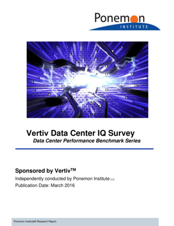
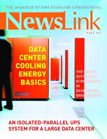
Data Center Network Architecture Options for 10 Gigabit EthernetThe chart below lists the typical data center network architectures applicable to the various 10GbE technologies.The table clearly shows 10GBASE-T technology provides greater design flexibility than its two copper counterparts.www.siemon.com1 0
THE FUTURE OF 10GBASE-TTIntel sees broad deployment of 10GbE in the form of 10GBASE-T. In 2010 fiber represents 44% of the 10GbE physical mediain data centers, but this percentage with continue to drop to approximately 12% by 2013. Direct-attach connections will growover the next few years to 44% by 2013 with large deployments in IP Data Centers and for High Performance Computing.10GBASE-T will grow from only 4% of physical media in 2010 to 44% in 2013 and eventually becoming the predominatemedia choice10GBASE-T as LOMSever OEMs will standardize on BASE-T as the media of choice for broadly deploying 10GbE for rack and tower servers.10GBASE-T provides the most flexibility in performance and reach. OEMs can create a single motherboard design to supportGbE, 10GbE, and any distance up to 100 meters. 1GBASE-T is the incumbent in the vast majority of data centers today, and10GBASE-T is the natural next step.ConclusionBroad deployment on 10GBASE-T will simplify data center infrastructures, making it easier to manage server connectivity whiledelivering the bandwidth needed for heavily virtualized servers and I/O-intensive applications. As volumes rise, prices will continue to fall, and new silicon processes have lowered power and thermal values. These advances make 10GBASE-T suitable forintegration on server motherboards. This level of integration, known as LAN on Motherboard (LOM) will lead to mainstream adoption of 10GbE for all server types in the data center.Source: Intel Market Forecastwww.siemon.com1 1
Hosted, Outsourced, and Cloud Data Centers Considerations for Overall SLAʼs for Facility Owners and Hosting ProvidersHosted and Outsourced Facility DefinitionsHosted data centers, both outsourced/managed and co-location varieties, provide a unique benefit for some customersthrough capital savings, employee savings and in some cases an extension of in-house expertise. Traditionally, thesefacilities were thought of as more SME (Small to Medium Enterprise) customers. However, many Global 500 companies have primary, secondary or ancillary data centers in outsourced locations. Likewise, co-location data centers are becomingincreasingly popular for application hosting such as web hosting and SaaS (Software as a Service), Infrastructure as aService (IaaS), Platform as a Service (PaaS) in Cloud computing. These models allow multiple customers to shareredundant telecommunications services and facilities while their equipment is colocated in a space provided by their serviceprovider. In-house bandwidth may be freed up at a companyʼs primary site for other corporate applications.1 2www.siemon.com
Hosted and outsourced/managed data centers arecenters that use alternative energy sources such as windgrowing rapidly for both companiesʼ primary and hot siteand solar.(failover ready) data centers, redundant sites and for smallto medium enterprises. Similarly, outsourced data centerThere are however, additional sources of revenue forservices are on the rise and allow a company to outsourceowners that have traditionally been overlooked.data center operations and locations, saving large capitalinclude packets passed, credits for power savingrequirements for items like generators, UPS/Powermeasures within tenant cages, lease of physical cabinetsconditioning systems and air handling units. As dataand cabling (both of which can be reused from one tenantcenter services increase, many providers can supply oneto the next) and monitoring of physical cabling changesor all of these models depending on a tenants needs. Thefor compliance and/or security along with traditionalvarious combinations of hosted/co-location and cloudnetwork monitoring.Theseservices available from hosting providers are blendingterms and services.For new spaces, a co-location owner can greatly mitigateissues over time with proper space planning. By having atConsiderations for the Hosted/Cloud Facilities Ownerleast one area of preconfigured cages (cabinets andpreinstalled cabling), the dynamic nature in that area andThe challenges for a hosted or cloud facility owner arethe resulting problems are diminished. This allows asimilar to the user considerations mentioned above, butcenter to better control airflow. Cabling can be leased asfor different reasons. While most facilities are built withpart of the area along with the cabinets, switch ports, etc.the expectation of full occupancy, the reconfiguration ofThis allows the cabinets to be move-in ready for quickeroccupancy due to attrition and customer changes canoccupancy.present the owner with unique challenges. The dynamicprovide increased revenue as the space does not need tonature of a tenant-based data center exacerbatesbe reconfigured for each new tenant. This area can alsoproblems such as cable abatement (removal ofbe used by more transient short term tenants that needabandoned cable), increasing power demand and coolingspace while their new data center or redundant site isissues.built.Data centers that have been in operation for several yearsIf factory terminated and tested trunking cable assemblieshave seen power bills increase and cooling needs changearenʼt used, it is important to use quality cabling so that- all under fixed contract pricing with their end-user, tenantthe cable plant does not impact Service Level Agreementscustomers. The dynamic nature of the raised floor area(SLAs). Both TIA 942 and ISO 24764 recommend afrom one tenant to the next compounds issues. Some co-minimum of category 6A/Class EA cabling. The minimumlocation owners signed fixed long-term contracts and findgrade of fiber is OM3 for multimode. Singlemode is alsothemselves trying to recoup revenue shortfalls from oneacceptable for longer distances and may be used forcage by adjusting new tenant contracts. Renegotiatingshorter distances, although the singlemode electronics willcontracts carries some risk and may lead to terminationbe higher priced.This rapidly deployed tenancy area willof a long-term contract.Owners must insist on quality installation companies ifContracts that are based on power per square foot plus athey allow tenants to manage their own cabling work. Anper square foot lease fee are the least effective if theowner may want to maintain a list of approved or certifiedpower number is based on average wattage and theinstallers. One bad installer in one cage can compromisecontract does not have inflationary clauses to cover risingother users throughout the facility. Approved installerselectricity costs. Power usage metering can be writtenprovide the owner with an additional control overinto contracts, however in some areas this requirespathways and spaces. Further, owners want to insist onspecial permission from either the power company orhigh performing standards-based and fully testedgoverning regulatory committees as it may be deemed asstructured cabling systems within the backbone networksreselling power. As environmental considerations gainand cages. Higher performing systems can provide amomentum, additional focus is being placed on datatechnical and marketing advantage over other owners that1 3www.siemon.com
While co-location owners historically stop their services atdeployment of customer areas. These trunks can bethe backbone, distributed switching via a centralizedreused and leased from tenant to tenant increasingcabling plant and patching area can provide significantrevenue and enabling near instant occupation.power savings through lower switch counts, enhancedpathway control and decreased risk of downtime duringFacility owners are typically under some type of SLAreconfigurations. All the while, the additional networkrequirements. SLAʼs can be for performance, uptime, anddistribution services provide increased revenue for the co-services. There are some network errors that are causedlocation owner. Managed and leased cabling ports canby poorly performing or underperforming cabling plants.be an additional revenue stream.Selecting high performing quality cabling solutions is onlypartial protection. The quality of the installation companyUnderstanding that some tenants will have specificis key for pathways, spaces, performance and error freerequirements, a combination of preconfigured and non-operation. Cabling has historically been an afterthought orpreconfigured cages may be required. For more dynamicdeemed to be the tenantʼs decision. By taking control ofnon-preconfigured areas, trunking assemblies, which arethe cabling in hosted spaces, the building owner removesfactory terminated and tested, allow the owner to offerthe cabling issues that can cause SLA violations, pathwayvarious cabling performance options, such as category 6problems, and ensure proper recycling of obsolete cabling.or 6A UTP, 6A shielded or category 7A fully shielded, tobest suit the end-userʼs needs. The owner can leaseWhile network monitoring can pinpoint ports that cause bitthese high performing cabling channels and, on theerrors and retransmission, determining if the cause isgreener side, the cabling can be reused from one tenantcabling related can be difficult.Noise is harder toto the next, eliminating on site waste and promotingtroubleshoot as it is intermittent.Testing the cablerecycling.requires that a circuit is down for the period of testing, butmay be necessary when SLAs are in dispute. WhileWhether pre-cabled or cabled upon move in, owner leasedintermittent retransmissions are relatively benign in normalor customer installed, category 6A or higher copper anddata retrieval, poorly performing cabling can make thisOM3/OM4 fiber or better should be used.Higherintermittent issue more constant. This can slow downminimumtransmissions, or in the case of voice and video, canrecommended standards, allows for higher speedbecome audible and visible. In short, cabling is roughlyapplications while providing backwards compatibility to3-5% of the overall network spend, but that 3-5% can keeplower speed technologies.the remaining 95-97% from functioning properly andperformingcablingconformstotheCategory 6A/Class EA,7/Class F and 7A/Class FA allow short reach (lower powerefficiently.mode) for 10GBASE-T communications under 30m for anadditional power savings to the owner. Category 7/7A andModularized Deployment for the Co-location/Hostedclass F/FA also provides the most noise immunity andFacilities Ownermeets strict government TEMPEST/EMSEC emissionsHosted and co-location facilities lend themselves well totests, meaning they are suitable for use in highly classifiedmodular POD-type scalable build outs. It is rare that thesenetworks alongside fiber. Installing the highest performingcenters are built with full occupancy on day one unlesscabling up front will result in longer cabling lifecycles thusthere is a sizeable anchor tenant/tenants. Spatial planningreducing the total cost of ownership and maximizing returnfor tenant considerations can sometimes be problematicon investment.due to varied size, power and rack space required bycustomers. These facilities are generally an open floorFor non-configured areas, the backbone can be distributedplan to start.into zones. The zone distribution area can be connectedmanner allows the owner to divide space in parcels whileto pods or modular units within a space. This modularaddressing hot/cold aisle requirements, cabling, and mostapproach allows customers to move equipment into theirimportantly scalability and versatility within the floor planareas one pod at a time. Preterminated copper and fiberspace. In a typical scenario, the space is allocated basedtrunking cables are easily configured to known lengthson cage layouts. The rows can be further subdivided forallowing the location owner to have stock on hand for rapidsmaller tenants, or cage walls can be removed for largerwww.siemon.com1 4Configuring spaces in a cookie cutter
Cloud facilities are generally highly occupied day one. AFor space planning, an owner typically defines zonesmodularized design approach in these environmentswithin the open space. Due to deeper equipment, aallows rows of cabinets to be deployed in a cookie cutterminimum of 3 feet (800 mm) should be allowed in allfashion. A structured cabling system that is pre-configuredaisles, or slider cage doors should be installed that willwithin cabinets, or ready for connection to banks ofprovide full access. If that is not possible, deepercabinets allows the owner to have a highly agile designequipment should be housed in the cabinets in front of thethat accommodates a wide variety of equipment changessliding doors so that cage walls donʼt block access. Awithout the need to run additional cabling channels in thefacility owned and operated cage can provide facility widefuture. There are two ways to deploy a modularized cloudnetworking, monitoring and connectivity services to otheror co-location data center. The first entails pre-cablingcages via preconfigured, pre-cabled, cabinets allowingcabinets and rows to a centralized patching area. Theservers to be moved in and plugged in on demand. Thesecond involves pre-cabling to zones within the datacabinets and networking services become part of thecenter. Once the zones are cabled, the addition of rows oftenant lease.cabinets within the zone becomes a matter of moving inthe new populated cabinets, and connecting them viaTo allow for a variety of customer size requirements, a setpatch cords to the zone cabling distribution area. Oneof caged areas can be provided with 2-4 preconfiguredcommon complaint with high density centers, such ascabinets for smaller tenants. By preplanning the spaces,clouds, is that equipment is often moved in with little to nocages do not need to move, pathways and spaces arenotice. By pre-cabling the data center to a centralizedpredefined and airflow can be optimized in hot/cold aisles.patching area or to zones, the reactionary and oftenIn reality, there may be tenants that move into one of theseexpensive last minute rush is eliminated.areas that do not need to fill the cabinets provided. Somefacilities allow for subleasing within cages.This allowsIf a centralized patching area is used, equipment changesunderutilized cabinets to be occupied by another tenantbecome a patch cord or fiber jumper change, allowingas long as access to the area is supervised and cabinetsrapid deployment. In a central patching (any to all)haveconfiguration, copper and/or fiber patch panels arecombinations and/or key locks. Even in a tenant designedprovided in the central patching area that corresponds tospace it is common for a cabinet or partial cabinet to gopatch panels in each cabinet. Connections to switching,unused. The benefit over time in pre-configured areas isservers, SAN, etc., are achieved via patch cords ratherthat the floor will remain unchanged from one tenant to thethan having to run new channels as new cabinets d.Another area with 8-10 cabinets is preconfigured forThe Need for Space Planningmedium size tenants. And another section/area is leftblankforthosetenantsthatrequiretheirownOne historical problem in open non-configured spaces hasconfiguration. The layout of that area should be completedbeen the varied customer configuration requirements andby the building owner to assure that hot aisle/cold aislethe need to fit as many customers into the floor space asplanning is consistent throughout the floor area.possible. As with any data center, growth without planningcan cause serious issues in a co-location/shared space.One cageʼs equipment running perpendicular to anothercage can cause undesirable hot air to be introduced intocold aisle of adjacent spaces. Haphazard and inconsistentcabling practices can block air flow. Improper use ofperforated tiles can cause loss of static pressure at the farsides of the space. In short, in a hosted space that is notproperly planned, problems can arise quickly.1 5www.siemon.com
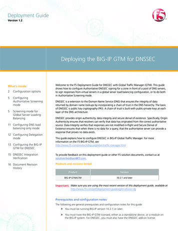
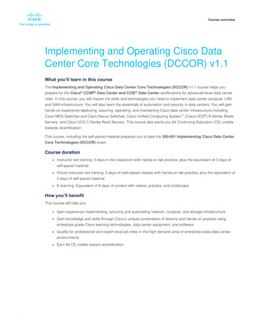
010203ZONE NMLKIJHGFEDCBA34Figure 1 – Sample space planIn the sample space plan above, we see caged areas of various sizes. Cage walls are static, cabling is centralized, andair flow is optimized. By providing varied numbers of cabinets within each cage, the floor plan can accommodate avariety of tenants. Tenants can occupy one or more cages depending on needs. For smaller tenants, individual cabinetsor smaller spaces can be leased providing room for growth. The static cage configuration provides a significant costsavings over time. Centralized patching may be provided for the entire floor or in each zone with connections to coreservices. This keeps cable lengths shorter, less expensive, and easier to manage.The above plan takes advantage of Siemonʼs VersaPOD cabinet line. The VersaPOD is available with a variety ofintegrated Zero U vertical patch panels (VPP) for support of copper and fiber patching.
Data Center Administrators have a number of 10GbE interfaces to choose from including CX4, SFP Fiber, SFP Direct Attach Copper (DAC), and 10GBASE-T. Today, most are choosing either 10GbE Optical or SFP DAC. However, limitations with each of these interfaces have kept them from being broadly deployed across the data center.