Transcription
Operating Instructions for theDG-700Pressure and Flow Gauge
Operating Instructions for theDG-700Pressure and Flow GaugeThe Energy Conservatory2801 21st Ave. S., Suite 160Minneapolis, MN 55407Ph.: (612) 827-1117Fax: (612) 827-1051www.energyconservatory.com
Manual Edition May 2012 2012 The Energy Conservatory. All rights reserved.ENERGY CONSERVATORY WARRANTYEXPRESS LIMITED WARRANTY:Seller warrants that this product, under normal use and service as described in the operator’s manual, shall be free from defects in workmanshipand material for a period of 24 months, or such shorter length of time as may be specified in the operator’s manual, from the date of shipment tothe Customer.LIMITATION OF WARRANTY AND LIABILITY:This limited warranty set forth above is subject to the following exclusions:a)b)c)d)With respect to any repair services rendered, Seller warrants that the parts repaired or replaced will be free from defects in workmanshipand material, under normal use, for a period of 90 days from the date of shipment to the Purchaser.Seller does not provide any warranty on finished goods manufactured by others. Only the original manufacturer’s warranty applies.Unless specifically authorized in a separate writing, Seller makes no warranty with respect to, and shall have no liability in connectionwith, any goods which are incorporated into other products or equipment by the Purchaser.All products returned under warranty shall be at the Purchaser’s risk of loss. The Purchaser is responsible for all shipping charges to returnthe product to The Energy Conservatory. The Energy Conservatory will be responsible for return standard ground shipping charges. TheCustomer may request and pay for the added cost of expedited return shipping.The foregoing warranty is in lieu of all other warranties and is subject to the conditions and limitations stated herein. NO OTHER EXPRESSOR IMPLIED WARRANTY IS PROVIDED, AND THE SELLER DISCLAIMS ANY IMPLIED WARRANTY OF FITNESS FORPARTICULAR PURPOSE OR MERCHANTABILITY.THE EXCLUSIVE REMEDY OF THE PURCHASER FOR ANY BREACH OF WARRANTY shall be the return of the product to the factoryor designated location for repair or replacement, or, at the option of The Energy Conservatory, refund of the purchase price.The Energy Conservatory’s maximum liability for any and all losses, injuries or damages (regardless of whether such claims are based oncontract, negligence, strict liability or other tort) shall be the purchase price paid for the products. IN NO EVENT SHALL THE SELLER BELIABLE FOR ANY SPECIAL, INCIDENTAL OR CONSEQUENTIAL DAMAGES. The Energy Conservatory shall not be responsible forinstallation, dismantling, reassembly or reinstallation costs or charges. No action, regardless of form, may be brought against the Seller morethan one year after the cause of action has accrued.The Customer is deemed to have accepted the terms of this Limitation of Warranty and Liability, which contains the complete and exclusivelimited warranty of the Seller. This Limitation of Warranty and Liability may not be amended or modified, nor may any of its terms be waivedexcept by a writing signed by an authorized representative of the Seller.TO ARRANGE A REPAIR: Please call The Energy Conservatory at 612-827-1117 before sending any product back for repair or to inquireabout warranty coverage. All products returned for repair should include a return shipping address, name and phone number of a contact personconcerning this repair, and the purchase date of the equipment.
Table of ContentsCHAPTER 1FEATURE SUMMARY1.1 Feature List11 1.1.a Pressure Measurements:1 1.1.b Auto Zeroing:1 1.1.c Time Averaging:1 1.1.d Air Flow and Velocity Measurements:1 1.1.e Display “HOLD”:1 1.1.f Specialized @ 50 and @ 25 Leakage Measurement Mode:2 1.1.g Specialized Air Handler Flow Measurement Mode:2 1.1.h Automated Blower Door Testing, Cruise Control and Data Logging:21.2 Overview of Gauge Operating Modes21.3 Gauge Face and Buttons31.4 Input/Output Ports on the DG-7004 1.4.a USB and Serial Communication Ports:4 1.4.b Fan Control Output Jack:4 1.4.c AC Power Input Jack:1.5 Overview of the Time Averaging Feature45 1.5.a Description of Time Averaging Periods:5 1.5.b Illustration of Time-Averaging Operation (First 10 seconds of operation):5 1.5.c Resetting the Time Averaging Measurement Buffer:51.6 Overview of the Baseline Pressure Measurement Feature (Channel A)6 1.6.a Buttons Used with Baseline Pressure Feature:6 1.6.b Restarting the Baseline Measurement:7 1.6.c Clearing and Exiting from the Baseline Pressure Procedure:71.7 Auto-Off FeatureCHAPTER 2PRESSURE/PRESSURE MODE782.1 Mode Summary82.2 Overview of Pressure/Pressure Mode82.3 Changing the Pressure Units82.4 Changing the Time Averaging Period92.5 Using the Baseline Pressure Feature9 2.5.a Example: Measuring Building Depressurization from an Exhaust FanCHAPTER 3PRESSURE/FLOW MODE9113.1 Mode Summary113.2 Overview of Pressure/Flow Mode113.3 Changing the Selected Test Device and Configuration113.4 “LO” Displayed on Channel B123.5 Changing the Air Flow Units123.6 Changing the Time Averaging Period123.7 Using the Baseline Pressure Feature in Pressure/Flow Mode12 3.7.a Example: Using the Baseline Feature During a Blower Door Depressurization Test12
3.7.b Entering Baseline Readings into TECTITE Software When Using the Baseline Feature:CHAPTER 4PRESSURE/FLOW @ 50 AND @ 25 MODES13144.1 Mode Summary144.2 Overview of Pressure/Flow @ 50 and @ 25 Modes14 4.2.a Pressure/Flow @ 50 Mode:14 4.2.b Pressure/Flow @ 25 Mode:14 4.2.c Benefits of Using the @ 50 and @ 25 Modes:154.3 Changing the Selected Test Device and Configuration154.4 “-----”or “LO” Displayed on Channel B154.5 Changing the Leakage Units164.6 Changing the Time Averaging Period164.7 Using the Baseline Pressure Feature in Pressure/Flow Mode164.8 Leakage Estimate Calculations Used in the @ 50 and @ 25 Modes16 4.8.a @ 50 Mode:16 4.8.b @ 25 Mode:17 4.8.c Errors in Leakage Estimates:17CHAPTER 5PRESSURE/AIR HANDLER FLOW MODE195.1 Mode Summary195.2 Overview of Pressure/Air Handler Flow Mode195.3 Changing the Selected Test Device and Configuration195.4 “-----”or “LO” Displayed on Channel B205.5 Changing the Air Handler Flow Units205.6 Changing the Time Averaging Period for the Step 2 Procedure205.7 Test Procedure For Measuring Air Handler Flow20 5.7.a Step 1: Measuring the NSOP20 5.7.b Step 2: Measuring the TFSOP and Adjusted Air Handler Flow215.8 Flow Resistance Correction Factors Used in the DG-700CHAPTER 6PRESSURE/VELOCITY MODE22236.1 Mode Summary236.2 Overview of Pressure/Velocity Mode236.3 Changing the Air Velocity Units236.4 Changing the Time Averaging Period236.5 Air Velocity Calculations Used in the DG-70023CHAPTER 7SERVICING AND MAINTENANCE7.1 Gauge Calibration and Servicing2424 7.1.a Calibration:24 7.1.b Servicing/Repairs:247.2 Low Battery Indicator/Battery Replacement24 7.2.a Low Battery Indicators:24 7.2.b Battery Replacement:247.3 Troubleshooting/Resetting the DG-70025
7.4 AC Power Supply SpecificationsAPPENDIX AQUICK GUIDES FOR USING THE DG-700 WITH ENERGYCONSERVATORY TEST DEVICES2526A.1 One-Point 50 Pascal Building Depressurization Test using the Model 3 Minneapolis Blower Door and DG-700 Digital Gauge26A.2 One-Point 25 Pascal Total Leakage Duct Pressurization Test Using the Seried B Minneapolis DuctBlaster and DG-700 Digital Gauge28A.3 Using the TrueFlow Air Handler Flow Meter and the DG-700 Digital Gauge30A.4 DG-700 Connections Needed to Conduct Automated Blower Door Tests32A.5 Using the DG-700's Cruise Control Feature36
Chapter 1Chapter 1Feature SummaryFeature SummaryThe DG-700 Pressure and Flow Gauge is a multi-functional differential pressure gauge with 2 independentmeasurement channels. In addition to providing high resolution pressure measurements, the DG-700 is programmedto operate with other Energy Conservatory test devices to provide air flow measurements during buildingperformance test procedures. The DG-700’s dual pressure channels and air flow measurement features make itideally suited for a wide range of building performance testing applications including: Blower Door airtightness testing.Duct system airtightness testing.Air handler flow measurements.Exhaust fan flow measurements.Building depressurization and combustion safety testing.1.1 Feature List 1.1.a Pressure Measurements:-Simultaneous display of 2 independent differential pressure channels (A and B).Each pressure channel has a range of –1,250 Pascals to 1,250 Pascals.Accuracy of pressure channels is /- 1% of reading, or 2 times the resolution, whichever is greater.Auto ranging with 0.1 Pascal resolution.Choice of pressure units (Pascals or Inches w.c.).Specialized “Baseline” feature on Channel A allows user to measure and record a baseline pressure reading,and then display the baseline adjusted pressure reading. 1.1.b Auto Zeroing:-Auto-zeroing feature for both measurement channels automatically adjusts for sensitivity to position andoperating temperature during operation (automatically activated every 10 seconds). 1.1.c Time Averaging:-Choice of 4 time-averaging options (1 second, 5 second, 10 second and Long-Term average). The timeaveraging feature stabilizes readings when measuring fluctuating signals (e.g. windy conditions). 1.1.d Air Flow and Velocity Measurements:-The DG-700 will calculate and display air flow readings on Channel B for the following Energy Conservatorytest devices: (choice of units - cubic feet per minute (CFM), meters3 per hour (m3/hr), liters per second (l/s)) -Model 3 Minneapolis Blower Door fans (110V and 220V).Model 4 Minneapolis Blower Door fans (220V).Series A and B Minneapolis Duct Blaster fans.Exhaust Fan Flow Meter.TrueFlow Air Handler Flow Meter.The DG-700 will calculate and display air velocity readings on Channel B from a standard pitot tube. (choice ofunits – feet per minute (FPM), meters per second (m/s)) 1.1.e Display “HOLD”:When the “HOLD” button is pushed, the DG-700 display is temporarily frozen with the most recent readings andsettings. The Hold feature is turned off by pushing the “HOLD” button a second time.1Operating Instructionsfor the DG700
Chapter 1Feature Summary 1.1.f Specialized @ 50 and @ 25 Leakage Measurement Mode:-For one-point airtightness tests of building and duct systems, the DG-700 will display on Channel B estimatedleakage rates adjusted to either 50 Pascals or 25 Pascals of test pressure.Choice of leakage units (CFM @, m3/hr @ , l/s @, sq. inches @ , sq. centimeters @). 1.1.g Specialized Air Handler Flow Measurement Mode:-Designed for measuring air handler flow rates using a TrueFlow Air Handler Flow Meter or a Duct Blaster fan.Automatically adjusts displayed air flow rate using measured system operating pressures (NSOP and TFSOP).Choice of air flow units (cfm, m3/hr, l/s). 1.1.h Automated Blower Door Testing, Cruise Control and Data Logging:-The DG-700 can be used along with a computer and specialized TEC software (TECTITE, TECTITE Expressor TECLOG2) to conduct fully automated Blower Door tests.The Cruise Control feature allows you to automatically control a Blower Door or Duct Blaster fan to maintain aconstant 75Pa, 50 Pa, 25 Pa or 0 Pa building pressure without having the gauge connected to a computer.Both of the DG-700’s pressure channel readings can be recorded using TEC’s TECLOG2 data logging software.1.2 Overview of Gauge Operating ModesModeApplicationChannel A DisplayChannel B DisplayPressure/Pressure(PR/ PR)Multi-purpose pressuremeasurements.Pressure in units chosen(Pa, in w.c.).Pressure in units chosen(Pa, in w.c.).Pressure/Flow(PR/ FL)Multi-purpose pressureand air flowmeasurements.Pressure in Pascals.Nominal (unadjusted) air flow from theselected Energy Conservatory testdevice, in units chosen (CFM, m3/h, l/s).Pressure/Flow @ 50 Pa(PR/ FL@50)Specialized mode forone-point Blower Doorbuilding airtightnesstest.Building pressure in Pascals.Building leakage at 50 Pascals in unitschosen (CFM@50, m3/h@50, l/s@50,in2@50, cm2@50). Leakage rate isdetermined by continuously adjustingthe measured air flow from the selectedBlower Door fan to a building pressureof 50 Pascals, using the real-timeChannel A building pressure reading.Pressure/Flow @ 25 Pa(PR/ FL @25)Specialized mode forone-point total leakageduct airtightness test.Duct system pressure inPascals.Total duct leakage at 25 Pa in unitschosen (CFM@25, m3/h@25, l/s@25,in2@25, cm2@25). Leakage rate isdetermined by continuously adjustingthe measured air flow from the selectedduct testing fan to a duct pressure of 25Pascals, using the real-time Channel Aduct pressure reading.Pressure/AH Flow(PR/ AH)Specialized mode formeasuring air handlerflow rates using aTrueFlow Air HandlerFlow Meter or a DuctBlaster fan.Normal system operatingpressure (NSOP) and testflow system operatingpressure (TFSOP) in Pascals.Total air handler flow in units chosen(CFM, m3/h, l/s). Air flow from theselected Energy Conservatory testdevice is continuously adjusted usingthe measured NSOP and TFSOPreadings from Channel A.Pressure/Velocity(PR/ V)Pressure and airvelocity measurements.Pressure in Pascals.Air velocity in units chosen(FPM, m/s).2Operating Instructionsfor the DG700
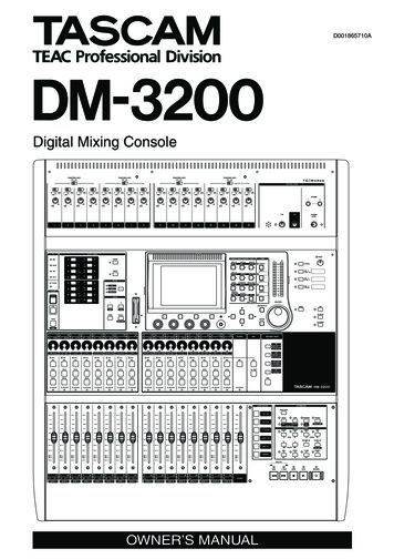
Chapter 1Feature Summary1.3 Gauge Face and ButtonsSelected test deviceconfiguration (for air flowmeasurements on Channel B)Selected test device (for airflow measurements onChannel B)Channel A ReadingChannel B ReadingSelected Time Averaging(for both Channels)Selected Operating ModeDisplay Hold IndicatorLow Battery IndicatorChannel A Input TapChannel B Input TapChannel A Reference TapButtonDEVICEUNITSCONFIGMODEChannel B Reference TapPurposeButtonUsed to select the Energy Conservatory test deviceconnected to Channel B (not active in PR/PRmode).BASELINEInitiates Baseline pressure measurement procedureon Channel A (not active in PR/AH mode).Selects the pressure and air flow units for ChannelsA and B.STARTUsed to start measurement procedure for Baselineand NSOP measurements. Also used to reset timeaveraging buffers and manually initiate auto-zero.Used to select the configuration for the currentlychosen test device (not active in PR/PR mode).ENTERUsed to accept and enter Baseline and NSOPpressure readings. After entering Baseline reading,Channel A will display baseline adjusted pressure.Selects the current operating mode.ON/OFFCLEARUsed to exit out of a Baseline pressuremeasurement procedure. When in PR/AH mode,resets gauge back to beginning of AH flowmeasurement procedure (i.e. NSOP measurement).Also used to turn off the Cruise Control feature.LIGHTTIME AVGUsed to select the time averaging mode (not activeduring Baseline and NSOP measurements).HOLDBegin CruiseInitiates Cruise Control feature (not active inPR/AH and PR/V modes).Start FanPurposeStop FanCruise TargetStarts the fan for Cruise Control.Turns gauge On and Off.Turns display backlight On and Off.Turns display Hold feature On and Off.Turns off the fan for Cruise Control.Used to select the Cruise Target Pressure.3Operating Instructionsfor the DG700
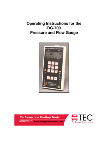
Chapter 1Feature Summary1.4 Input/Output Ports on the DG-700 1.4.a USB and Serial Communication Ports:The DG-700 contains both a USB and a DB-9 serial communication port, either of which can be used to create a 2way communication link between the gauge and a computer. This communication link can be used (along with TECsoftware) to conduct automated Blower Door tests and to data log both pressure channels.-Automated Blower Door testing requires the TECTITE, TECTITE Express or TECLOG2 software, a BlowerDoor fan speed controller with a communication jack (standard equipment since September 2004), a fan controlcable, and a communication cable (either USB or 9 pin serial) to connect the DG-700 to a user supplied laptopcomputer.-Data logging of pressure measurements requires the TECLOG2 software (available fromwww.energyconservatory.com), and a communication cable (either USB or 9 pin serial) to connect the DG-700to a user supplied laptop computer. 1.4.b Fan Control Output Jack:The fan control output jack provides a speed control signal which is used to control a Blower Door or Duct Blasterfan during an automated Blower Door test, or with the Cruise Control feature. A fan control cable is used to connectthe fan control output jack to the communication jack on the side of the fan speed controller. 1.4.c AC Power Input Jack:The AC power input jack can be used with an optional AC power supply to provide a long term power source for thegauge (to be used when data logging). The gauge is normally powered by 6 AA batteries located in the rear batterycompartment. When the AC power supply is plugged in, the power supply bypasses the batteries in the batterycompartment. See Chapter 7 for AC power supply specifications. Note: Always turn off the gauge before pluggingin the AC power Fan ControlOutput JackAC Power Input JackCommunication Jacks(Blower Door andDuct Blaster SpeedControllers)4Operating Instructionsfor the DG700
Chapter 1Feature Summary1.5 Overview of the Time Averaging FeatureThe DG-700 has a choice of 4 time averaging periods which are applied to both measurement channels.When the gauge is turned on, the default time averaging period is 1 second average. To change theselected time averaging period, press the TIME AVG button. The currently selected time averagingperiod is shown in the TIME AVG portion of the gauge display. 1.5.a Description of Time Averaging Periods:-1 Second Average (1) – Both measurement channels are updated once per second with the average of thereadings from the previous 1 second. The 1 Second Average is the default time averaging period when turningon the gauge, and is the period most commonly used.-5 Second Average (5) – Both measurement channels are updated once every 5 seconds with the average of thereadings from the previous 5 second period. When first activated, the display shows "---" until the first 5 secondmeasurement buffer has been recorded. The 5 Second Average should be used when the 1 Second Averagereading is fluctuating more than desired.-10 Second Average (10) – Both measurement channels are updated once every 10 seconds with the average ofthe readings from the previous 10 second period. When first activated, the display will show"---" until the first 10 second measurement buffer has been recorded. The 10 Second Average mode should beused when the 5 Second Average reading is fluctuating more than desired.-Long Term Average (L) – Both measurement channels are updated once per second with the running average ofall readings taken after the Long Term Average period is activated. When using Long Term Average, the gaugecontinuously adds the current measurements to the measurement buffer and displays the average value of allrecorded measurements. The gauge will operate for approximately 2 hours when using Long Term Averagebefore the measurement buffer is overloaded. When the buffer is overloaded, both channel readings will re-starta new long-term average period. 1.5.b Illustration of Time-Averaging Operation (First 10 seconds of operation):1 Second Average:Seconds: 1235 Second Average:45678910Seconds: 1234Pressure 12 5 10 2Signal:6 158 1226Pressure 12 5 10 2Signal:Display: 12 5 10 26 158 1226Display: -- --10 Second Average:Seconds: 123-- -- --66 15-- 7788 129102677779678Long Term Average:4Pressure 12 5 10 2Signal:Display:--5566 15-- -- --79108 12826---- 8--Seconds: 1910Pressure 12 5 10 2Signal:2346 158 1226Display: 12 978889 7589 1.5.c Resetting the Time Averaging Measurement Buffer:When using the 5 second, 10 second or Long Term averages, it is sometimes desirable to reset andrestart the time averaging measurement buffer when an unwanted signal has been recorded during a timeaveraging period (e.g. someone steps on the tubing during a Long Term Average measurement). To resetand restart the time averaging measurement buffer for both channels, press the START button.5Operating Instructionsfor the DG700
Chapter 1Feature Summary1.6 Overview of the Baseline Pressure Measurement Feature (Channel A)The Baseline feature on Channel A allows the user to measure and record a baseline pressure reading, and thendisplay the baseline adjusted pressure on the gauge. For purposes of this manual a baseline pressure reading isdefined as a pressure measurement made under a specific operating condition, which will be used to determine thechange in pressure created by a change in the operating condition.A common building performance application requiring use of a baseline pressure reading is determining the extent ofbuilding depressurization caused by turning on an exhaust fan. In order to accurately quantify the buildingdepressurization, the user first needs to know the building pressure (with reference to outside) prior to the exhaustfan being turned on. This initial pressure reading, known as the baseline building pressure, can be quickly measuredand then used to adjust the final building pressure reading (after the exhaust fan is turned on) to determine the actualchange in building pressure caused by fan operation. In the example below, the building depressurization measuredfrom the exhaust fan operating is –4.2 Pascals (i.e. the building pressure changed from –2.6 Pa to –6.8 Pa when theexhaust fan was turned on).0-1Change in BuildingPressure FromTurning On anExhaust Fan (Pa)-2.6-2-3-4-5-4.2BaselineBuildingPressure(Fan Off)-6.8-6-7BuildingPressure(Fan On)BaselineAdjustedBuildingPressure(Change fromTurning Fan On) 1.6.a Buttons Used with Baseline Pressure Feature:Pressing the BASELINE button initiates the baselinepressure measurement feature. The word“BASELINE” will begin to flash in the Channel Adisplay, indicating that the baseline feature is active. At thispoint, the gauge is monitoring the real-time Channel A pressurereading, but is not recording the reading. The Channel B displayis not active at this time.Press the START button to begin recording abaseline pressure reading. Once the START buttonis pressed, the word “BASELINE” stops flashing andthe gauge begins recording a long term average baselinepressure reading on Channel A. During the baselinemeasurement procedure, the Channel B display is used as atimer to let the user know how long (in seconds) the baselinemeasurement has been active. The longer the measurement time, generally the more stable the baseline readingtypically becomes.6Operating Instructionsfor the DG700
Chapter 1Feature SummaryOnce you are satisfied with the baseline pressurereading, press the ENTER key to accept and enterthe baseline pressure reading into the gauge. Afterpressing ENTER, Channel A will now display the baselineadjusted pressure reading (i.e. the measured baseline pressurereading will be subtracted from the current Channel A pressuremeasurement). The icon “ADJ” appears in the Channel A display to indicate that the baseline adjusted pressurereading is displayed. The time averaging period for the gauge reverts back to whatever period was selected prior topressing the BASELINE button. In addition, Channel B also reverts back to displaying an unadjusted pressurereading.Now create a change in the operating condition of the building(e.g. turn on and exhaust fan). Channel A will display thechange in building pressure caused by the change in operatingcondition. 1.6.b Restarting the Baseline Measurement:During a baseline measurement procedure (i.e. while the gauge is recording the long term averagebaseline pressure), the baseline measurement procedure can be restarted by pressing the START button.When START is pressed, the measurement buffer and time counter for the baseline reading is clearedand a new baseline reading is immediately started.Once a baseline measurement has been taken and entered into the gauge (i.e. ADJ appears below theChannel A reading), a new baseline measurement procedure can be initiated by pressing theBASELINE button. 1.6.c Clearing and Exiting from the Baseline Pressure Procedure:Pressing the CLEAR button clears the baseline measurement buffer and turns the baseline feature off.The gauge will remain in the operating mode selected prior to the BASELINE button being pressed.Note: If the gauge Mode is changed while the baseline measurement feature is active, the baseline measurementbuffer is cleared and the baseline feature is turned off.1.7 Auto-Off FeatureIn order to preserve battery life, the DG-700 gauge will automatically shut off if no keys are pressed for 2 hours. Theauto-off feature can be disabled by simultaneously pressing the CLEAR and ENTER buttons. The auto-off featureis automatically re-enabled whenever the gauge is turned off and then back on.7Operating Instructionsfor the DG700
Chapter 2Chapter 2Pressure/Pressure ModePressure/Pressure Mode2.1 Mode SummaryModeApplicationChannel A DisplayChannel B remeasurements.Pressure in units chosen(Pa, in w.c.).Pressure in units chosen(Pa, in w.c.).2.2 Overview of Pressure/Pressure ModeThe DG-700 gauge is turned on by pressing theON/OFF button once. When first turned on, the gaugeis automatically placed in the Pressure/Pressure(PR/PR) operating mode and immediately begins monitoring anddisplaying pressure readings for both Channels A and B. Thedefault pressure units for both channels is Pascals, and the defaulttime averaging period is 1 second average.Each channel on the DG-700 measures the pressure difference between either of the top Input pressure taps and itscorresponding bottom Reference pressure tap. The gauge can monitor and display both positive and negativepressure readings (i.e. bi-directional). In order to display the correct "sign" of the pressure reading (i.e. positive ornegative), it is important that the pressure taps are used consistently and logically. The top Input taps should alwaysbe connected to the pressure signal(s) you are trying to measure. The bottom Reference taps should always beconnected to the reference pressure(s) you are measuring the pressure signal with reference to.For example, let's set up the gauge to measure the pressure in a house with reference to outside using Channel A. Ifyou are standing in the house, connect tubing to the Channel A Reference tap and run it outside, while leaving theChannel A Input tap open to the house. The gauge will now display the pressure difference between the house andoutside, along with the correct sign of the reading. If the house is at a lower pressure than outside (e.g. from anexhaust fan running), then the pressure reading displayed on the gauge will have a minus sign "-" in front of thereading.On the other hand, if you are standing outside and wish to make the same reading, connect a piece of tubing to theChannel A Input tap and run it into the house, while leaving the Channel A Reference tap open to the outside. Thegauge will now display the same house to outside pressure difference as above, along with the correct sign. Note: Ineither case, if you had connected the tubing to the wrong tap on Channel A, the display would show the correctdifferential pressure reading, however, the reading would have the wrong sign.2.3 Changing the Pressure UnitsWhen in the PR/PR operating mode, the DG-700 can display pressure readings in units of Pascals orinches w.c. The default pressure units for the gauge is Pascals for both Channels A and B. To changethe pressure units for both channels, press the UNITS button. The selected pressure units are shown onthe gauge display directly below each of the channel readings.8Operating Instructionsfor the DG700
Chapter 2Pressure/Pressure Mode2.4 Changing the Time Averaging PeriodThe DG-700 has a choice of 4 time averaging periods which are applied to both pressure measurementchannels. The default time averaging period is 1 second average. To change the selected time averagingperiod, press the TIME AVG button. The selected time averaging period is shown in the TIME AVGportion of the gauge display. (See Section 1.5 for an overview of the time averaging feature).2.5 Using the Baseline Pressure FeatureThe Baseline feature on Channel A allows the user to measure and record abaseline pressure reading, and then display the baseline adjusted pressure reading.(See Section 1.6 for an overview of the baseline pressure feature) 2.5.a Example: Measuring Building Depressurization from an Exhaust FanA common building performance application requiring use of a baseline pressure reading is determining the extent ofbuilding depressurization caused by turning on an exhaust fan. In order to accurately quantify the buildingdepressurization, the user first needs to know the building pressure (with reference to outside) prior to the exhaustfan being turned on. This initial pressure reading, known as the baseline building pressure, can be quickly measuredand then used to adjust the final building pressure reading (after the exhaust fan is turned on) to determine the actualchange in building pressure caused by fan operation.-Set up Channel A to measure building pressure with reference to outside (e.g. run tubing from the Channel AReference tap to outside and leave the Channel A Input tap open to the building – assumes the gauge is in thebuilding).-With the exhaust fan off, turn on the gauge and leave it in the PR/PR mode.-Press the BASELINE button. The word “BASELINE” willbegin to flash in the Channel A display, indicating that thebaseline feature has been initiated. At this point, the gauge ismonitoring the real-time Channel A baseline pressurereading, but is not recording the reading. The Channel Bdisplay is not active at this time.-Press the START button to begin the baseline measurementprocedure on Channel A. Once the START button ispressed, the word “BASELINE” stops flashing and thegauge begins recording a long term average baselinepressure reading on Channel A. During the baselinemeasurement procedure, the Channel
A.1 One-Point 50 Pascal Building Depressurization Test using the Model 3 Minneapolis Blower Door and DG-700 Digital Gauge 26 A.2 One-Point 25 Pascal Total Leakage Duct Pressurization Test Using the Seried B Minneapolis Duct Blaster and DG-700 Digital Gauge 28File Size: 946KB