Transcription
Dell Vostro 3360Owner's ManualRegulatory Model: P32GRegulatory Type: P32G001
Notes, Cautions, and WarningsNOTE: A NOTE indicates important information that helps you make better use of your computer.CAUTION: A CAUTION indicates either potential damage to hardware or loss of data and tells you how to avoid theproblem.WARNING: A WARNING indicates a potential for property damage, personal injury, or death. 2012 Dell Inc.Trademarks used in this text: Dell , the Dell logo, Dell Precision , OptiPlex , Latitude , PowerEdge , PowerVault ,PowerConnect , OpenManage , EqualLogic , Compellent , KACE , FlexAddress , Force10 and Vostro are trademarks of DellInc. Intel , Pentium , Xeon , Core and Celeron are registered trademarks of Intel Corporation in the U.S. and other countries. AMD is a registered trademark and AMD Opteron , AMD Phenom and AMD Sempron are trademarks of Advanced Micro Devices, Inc.Microsoft , Windows , Windows Server , Internet Explorer , MS-DOS , Windows Vista and Active Directory are either trademarksor registered trademarks of Microsoft Corporation in the United States and/or other countries. Red Hat and Red Hat Enterprise Linux are registered trademarks of Red Hat, Inc. in the United States and/or other countries. Novell and SUSE areregistered trademarks of Novell Inc. in the United States and other countries. Oracle is a registered trademark of Oracle Corporationand/or its affiliates. Citrix , Xen , XenServer and XenMotion are either registered trademarks or trademarks of Citrix Systems, Inc. inthe United States and/or other countries. VMware , Virtual SMP , vMotion , vCenter and vSphere are registered trademarks ortrademarks of VMware, Inc. in the United States or other countries. IBM is a registered trademark of International Business MachinesCorporation.2012 - 06Rev. A00
ContentsNotes, Cautions, and Warnings.21 Working on Your Computer.5Before Working Inside Your Computer.5Turning Off Your Computer.6After Working Inside Your Computer.62 Removing and Installing Components.9Recommended Tools.9Removing the Subscriber Identity Module (SIM) Card.9Installing the SIM Card.10Removing the Security Digital (SD) Card.10Installing the Secure Digital Card.10Removing the Access Panel.10Installing the Access Panel.11Removing the Wireless Local Area Network (WLAN) Card.11Installing the WLAN Card.11Removing the Coin-Cell Battery.11Installing the Coin-Cell Battery.12Removing the Memory.12Installing the Memory.12Removing the Keyboard.12Installing the Keyboard.14Removing the Palmrest.14Installing the Palmrest.17Removing the Battery.18Installing the Battery.19Removing the Hard Drive.19Installing the Hard Drive.20Removing the Display-Hinge Cover.21Installing the Display Hinge Cover.21Removing the Display Assembly.22Installing the Display Assembly.22Removing the Display Bezel.23Installing the Display Bezel.24Removing the Display Panel.24Installing the Display Panel.27
Removing the Camera Module.27Installing the Camera Module.28Removing the Fan.28Installing the Fan.29Removing the System Board.29Installing the System Board.31Removing the Heat Sink.31Installing the Heat Sink.32Removing the Speakers.32Installing the Speakers.33Removing the Power Connector.34Installing the Power Connector.34Removing the Input/Output (I/O) board.34Installing the I/O Board.353 System Setup.37Boot Sequence.37Navigation Keys.37System Setup Options.38Updating the BIOS .42System and Setup Password.42Assigning a System Password and Setup Password.42Deleting or Changing an Existing System and/or Setup Password.434 Diagnostics.45Enhanced Pre-Boot System Assessment (ePSA) Diagnostics.45Device Status Lights.45Battery Status Lights.46Diagnostic Beep Codes.465 Specifications.496 Contacting Dell.55
Working on Your Computer1Before Working Inside Your ComputerUse the following safety guidelines to help protect your computer from potential damage and to help to ensure yourpersonal safety. Unless otherwise noted, each procedure included in this document assumes that the followingconditions exist: You have performed the steps in Working on Your Computer. You have read the safety information that shipped with your computer. A component can be replaced or--if purchased separately--installed by performing the removal procedure inreverse order.WARNING: Before working inside your computer, read the safety information that shipped with your computer. Foradditional safety best practices information, see the Regulatory Compliance Homepage at www.dell.com/regulatory complianceCAUTION: Many repairs may only be done by a certified service technician. You should only performtroubleshooting and simple repairs as authorized in your product documentation, or as directed by the online ortelephone service and support team. Damage due to servicing that is not authorized by Dell is not covered by yourwarranty. Read and follow the safety instructions that came with the product.CAUTION: To avoid electrostatic discharge, ground yourself by using a wrist grounding strap or by periodicallytouching an unpainted metal surface, such as a connector on the back of the computer.CAUTION: Handle components and cards with care. Do not touch the components or contacts on a card. Hold acard by its edges or by its metal mounting bracket. Hold a component such as a processor by its edges, not by itspins.CAUTION: When you disconnect a cable, pull on its connector or on its pull-tab, not on the cable itself. Somecables have connectors with locking tabs; if you are disconnecting this type of cable, press in on the locking tabsbefore you disconnect the cable. As you pull connectors apart, keep them evenly aligned to avoid bending anyconnector pins. Also, before you connect a cable, ensure that both connectors are correctly oriented and aligned.NOTE: The color of your computer and certain components may appear differently than shown in this document.To avoid damaging your computer, perform the following steps before you begin working inside the computer.1.Ensure that your work surface is flat and clean to prevent the computer cover from being scratched.2.Turn off your computer (see Turning Off Your Computer).3.If the computer is connected to a docking device (docked) such as the optional Media Base or Battery Slice,undock it.CAUTION: To disconnect a network cable, first unplug the cable from your computer and then unplug the cablefrom the network device.4.Disconnect all network cables from the computer.5.Disconnect your computer and all attached devices from their electrical outlets.5
6.Close the display and turn the computer upside-down on a flat work surface.NOTE: To avoid damaging the system board, you must remove the main battery before you service the computer.7.Remove the main battery.8.Turn the computer top-side up.9.Open the display.10. Press the power button to ground the system board.CAUTION: To guard against electrical shock, always unplug your computer from the electrical outlet beforeopening the display.CAUTION: Before touching anything inside your computer, ground yourself by touching an unpainted metalsurface, such as the metal at the back of the computer. While you work, periodically touch an unpainted metalsurface to dissipate static electricity, which could harm internal components.11. Remove any installed ExpressCards or Smart Cards from the appropriate slots.Turning Off Your ComputerCAUTION: To avoid losing data, save and close all open files and exit all open programs before you turn off yourcomputer.1.Shut down the operating system:–In Windows 7:Click Start–, then click Shut Down.In Windows Vista :Click Start, then click the arrow in the lower-right corner of the Start menu as shown below, and thenclick Shut Down.–In Windows XP:Click Start Turn Off Computer Turn Off . The computer turns off after the operating system shutdownprocess is complete.2.Ensure that the computer and all attached devices are turned off. If your computer and attached devices did notautomatically turn off when you shut down your operating system, press and hold the power button for about 4seconds to turn them off.After Working Inside Your ComputerAfter you complete any replacement procedure, ensure you connect any external devices, cards, and cables beforeturning on your computer.CAUTION: To avoid damage to the computer, use only the battery designed for this particular Dell computer. Do notuse batteries designed for other Dell computers.1.Connect any external devices, such as a port replicator, battery slice, or media base, and replace any cards, suchas an ExpressCard.2.Connect any telephone or network cables to your computer.6
CAUTION: To connect a network cable, first plug the cable into the network device and then plug it into thecomputer.3.Replace the battery.4.Connect your computer and all attached devices to their electrical outlets.5.Turn on your computer.7
8
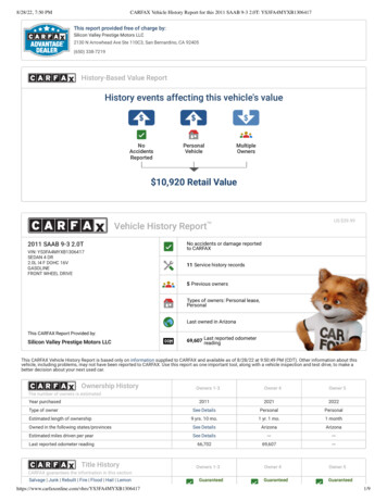
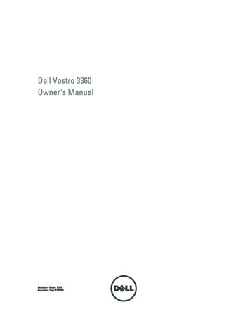
Removing and Installing Components2This section provides detailed information on how to remove or install the components from your computer.Recommended ToolsThe procedures in this document may require the following tools: Small flat-blade screwdriver Phillips screwdriver Small plastic scribeRemoving the Subscriber Identity Module (SIM) Card1.Follow the procedures in Before Working Inside Your Computer.2.Insert a paper clip into the small hole on the SIM-card holder to release it from the computer.3.Remove the SIM-card holder from the computer.9
4.Remove the SIM card from the SIM-card holder.Installing the SIM Card1.Place the SIM card into the SIM-card holder.2.Slide the SIM card holder together with the SIM card into its slot.3.Follow the procedures in After Working Inside Your Computer.Removing the Security Digital (SD) Card1.Follow the procedures in Before Working Inside Your Computer.2.Press in on the SD card to release it from the computer. Slide the SD card out of the computer.Installing the Secure Digital Card1.Push the SD card into the slot until it clicks into place.2.Follow the procedures in After Working Inside Your Computer.Removing the Access Panel1.Follow the procedures in Before Working Inside Your Computer.2.Remove the screw that secures the access panel to the computer.3.Remove the access panel from the computer.10
Installing the Access Panel1.Place the access panel to its original position on the computer.2.Tighten the screw to secure the access panel to the computer.3.Follow the procedures in After Working Inside Your Computer.Removing the Wireless Local Area Network (WLAN) Card1.Follow the procedures in Before Working Inside Your Computer.2.Remove the access panel.3.Disconnect the antenna cables from the WLAN card and remove the screw that secures the WLAN card to thecomputer. Remove the WLAN card from the computer.Installing the WLAN Card1.Slide the WLAN card into its slot.2.Connect the antenna cables according to the color code on the WLAN card.3.Install the access panel.4.Follow the procedures in After Working Inside Your Computer.Removing the Coin-Cell Battery1.Follow the procedures in Before Working Inside Your Computer.2.Remove the access panel.3.Use a plastic scribe to pry the battery from the socket and lift the coin-cell battery out of the computer.11
Installing the Coin-Cell Battery1.Push the coin-call battery into its slot on the system board.2.Install the access panel.3.Follow the procedures in After Working Inside Your Computer.Removing the Memory1.Follow the procedures in Before Working Inside Your Computer.2.Remove the access panel.3.Use your fingertips to spread apart the securing clips on each end of the memory module connector until thememory module pops up and remove the memory module from its connector on the system board by drawing themodule from the system board at 45-degree angle.Installing the Memory1.Insert and secure the memory module to the system board.2.Install the access panel.3.Follow the procedures in After Working Inside Your Computer.Removing the Keyboard1.Follow the procedures in Before Working Inside Your Computer.2.Remove the screw that secures the keyboard to the chassis.12
3.Starting on the right side of the system, use a plastic scribe to pry up the keyboard from the computer.4.Flip the keyboard over and lay it on the palmrest.5.Lift the clip to release the keyboard cable and disconnect it from the computer.13
Installing the Keyboard1.Connect the keyboard cable to the system board.2.Place the keyboard back to its original position.3.Tighten the screw to secure the keyboard to the computer.4.Follow the procedures in After Working Inside Your Computer.Removing the Palmrest1.Follow the procedures in Before Working Inside Your Computer.2.Remove:a) access panelb) keyboardc) display hinge cover3.Using a plastic scribe pry out the rubber pads that cover the front screws on the base cover.4.Remove the screws that secure the palmrest to the computer.14
5.Disconnect the quick launch board cable, the finger print reader cable, and the palmrest cable from the systemboard.6.Disconnect the power LED cable and the LED board cable from the system board.15
7.Remove the screws that secure the palmrest to the front of the computer.8.Pry along the edges of the palmrest to release the palmrest.16
9.Lift the palmrest up and away from the computer.Installing the Palmrest1.Starting from the edges of the palmrest, press downwards on the palmrest to engage the tabs on the computer.2.Tighten the screws to secure the palmrest to the front of the computer.3.Connect the power LED cable and the LED board cable to the system board.4.Connect the quick launch board cable, the finger print reader cable, and the palmrest cable to the system board.5.Tighten the screws to secure the palmrest to the back of the computer.6.Push the rubber pads to cover the screws on the computer.7.Install the keyboard.8.Install the access panel.9.Follow the procedures in After Working Inside Your Computer.17
Removing the Battery1.Follow the procedures in Before Working Inside Your Computer.2.Remove the:a) access panelb) keyboardc) palmrest3.Disconnect the battery cable from the system board.4.Remove the screws that secure the battery to the system board.5.Remove the battery from the computer.18
Installing the Battery1.Place the battery into the battery bay.2.Replace and tighten the screws that secure the battery to the computer.3.Connect the battery cable to the system board.4.Install:a) palmrestb) keyboardc) access panel5.Follow the procedures in After Working Inside Your Computer.Removing the Hard Drive1.Follow the procedures in Before Working Inside Your Computer.2.Remove the:a) access panelb) keyboardc) palmrestd) battery3.Remove the screws that secure the hard drive to the computer.19
4.Lift the hard drive to disconnect the hard-drive cable.5.Disconnect the hard-drive cable from the hard drive and remove the hard drive from the computer.6.Remove the screws that secure the hard-drive bracket to the hard drive and remove the hard drive bracket from it.Installing the Hard Drive1.Tighten the screws to secure the hard drive bracket to the hard drive.2.Connect the hard drive cable to the hard drive and place the hard drive back to its original position on thecomputer.3.Tighten the screws to secure the hard drive to the oardaccess panelFollow the procedures in After Working Inside Your Computer.
Removing the Display-Hinge Cover1.Follow the procedures in Before Working Inside Your Computer.2.Remove the access panel.3.Remove the screws that secure the display-hinge cover to the computer.4.Remove the display-hinge cover from the computer.Installing the Display Hinge Cover1.Align the display hinge cover to its original position on the computer.2.Tighten the screws to secure the display hinge cover to the computer.3.Install the access panel.4.Follow the procedures in After Working Inside Your Computer.21
Removing the Display Assembly1.Follow the procedures in Before Working Inside Your Computer.2.Remove the:a)b)c)d)e)access panelkeyboardpalmrestbatterydisplay hinge cover3.Release the antenna cables from their routing.4.Disconnect the display cable from the system board and remove the screws that secure the display assembly tothe computer.Installing the Display Assembly1.Connect the display cable to the system board and tighten the screws to secure the display assembly to thecomputer.2.Thread the hard drive cable through its routing tabs.3.Thread the antenna cables through their routing tabs.4.Install :a)b)c)d)22display hinge coverbatterypalmrestkeyboard
e) access panel5.Follow the procedures in After Working Inside Your Computer.Removing the Display Bezel1.Follow the procedures in Before Working Inside Your Computer.2.Remove:a)b)c)d)e)access panelkeyboardpalmrestbatterydisplay assembly3.Using a plastic scribe, pry under the display bezel to release it from the display assembly.4.Lift the display bezel and remove it from the display assembly.23
Installing the Display Bezel1.Align the display bezel with the display assembly and gently snap it into place.2.Install :a)b)c)d)e)3.display hinge coverbatterypalmrestkeyboardaccess panelFollow the procedures in After Working Inside Your Computer.Removing the Display Panel1.Follow the procedures in Before Working Inside Your Computer.2.Remove:a)b)c)d)e)f)g)access panelkeyboardpalmrestbatterydisplay hinge coverdisplay assemblydisplay bezel3.Disconnect the camera cable from its connector on the camera module.4.Remove the screws that secure the display panel to the display back cover.24
5.Flip the display panel from the display assembly.6.Place the display panel with its front facing down to access the display and camera cables attached to it.25
7.Pull out the plastic tab to disconnect the display cable from the display panel.8.Remove the camera cable from the display panel.26
Installing the Display Panel1.Place the camera cable on the back of the display panel.2.Connect the display cable to its connector on the display panel.3.Place the display panel to its original position on the display assembly.4.Tighten the screws to secure the display panel to the display assembly.5.Connect the camera cable to camera module.6.Install :a)b)c)d)e)f)g)7.display bezeldisplay assemblydisplay hinge coverbatterypalmrestkeyboardaccess panelFollow the procedures in After Working Inside Your Computer.Removing the Camera Module1.Follow the procedures in Before Working Inside Your Computer.2.Remove:a)b)c)d)e)f)g)3.access panelkeyboardpalmrestbatterydisplay hinge coverdisplay assemblydisplay bezelDisconnect the camera cable from the camera module and remove the camera module from the display assembly.27
Installing the Camera Module1.Connect the camera cable to the camera module and place the camera module to its original position on thedisplay assembly.2.Install :a)b)c)d)e)f)g)3.display bezeldisplay assemblydisplay hinge coverbatterypalmrestkeyboardaccess panelFollow the procedures in After Working Inside Your Computer.Removing the Fan1.Follow the procedures in Before Working Inside Your Computer.2.Remove:a)b)c)d)e)f)3.28access panelkeyboardpalmrestbatterydisplay hinge coverdisplay assemblyRemove the screw that secures the fan to the computer. Then, lift the fan and disconnect the fan cable from thesystem board.
Installing the Fan1.Connect the fan cable to the system board.2.Tighten the screws to secure the fan to the computer.3.Install :a)b)c)d)e)f)4.display assemblydisplay hinge coverbatterypalmrestkeyboardaccess panelFollow the procedures in After Working Inside Your Computer.Removing the System Board1.Follow the procedures in Before Working Inside Your Computer.2.Remove:a)b)c)d)e)f)3.access panelkeyboardpalmrestdisplay hinge coverdisplay assemblyfanDisconnect the I/O cable from the I/O daughter board.29
4.Remove the screws that secure the system board to the computer.5.Remove the hard-drive cable from its routing and flip the system board to access the power connector cable.6.Disconnect the power-connector cable from the system board.30
Installing the System Board1.Connect the power connector cable to the system board.2.Thread the hard drive cable through its routing tabs.3.Tighten the screws to secure the system board to the computer.4.Connect the I/O board cable to the I/O board.5.Install :a) fanb) display assemblyc) display hinge coverd) batterye) palmrestf) keyboardg) access panel6.Follow the procedures in After Working Inside Your Computer.Removing the Heat Sink1.Follow the procedures in Before Working Inside Your Computer.2.Remove:a) access panelb) keyboardc) palmrestd) display hinge covere) display assemblyf) fang) system board3.Remove the screws that secure the heat sink to the system board.31
4.Remove the heat sink from the system board,Installing the Heat Sink1.Tighten the screws to secure the heat sink to the system board.2.Install :a)b)c)d)e)f)g)h)3.system boardfandisplay assemblydisplay hinge coverbatterypalmrestkeyboardaccess panelFollow the procedures in After Working Inside Your Computer.Removing the Speakers1.Follow the procedures in Before Working Inside Your Computer.2.Remove:a)b)c)d)e)3.32access panelkeyboardpalmrestbatteryhard driveDisconnect the speaker cable from the I/O board.
4.Release the speaker cables from their routing and remove the speakers from the computer.Installing the Speakers1.Place the speakers on the computer and thread the speakers cable through the routing tabs.2.Connect the speaker cable to the I/O board3.Install :a)b)c)d)e)4.hard drivebatterypalmrestkeyboardaccess panelFollow the procedures in After Working Inside Your Computer.33
Removing the Power Connector1.Follow the procedures in Before Working Inside Your Computer.2.Remove:a)b)c)d)e)f)g)h)3.access panelkeyboardpalmrestbatterydisplay hinge coverdisplay assemblyfansys
NOTE: The powered USB 3.0 connector also supports Microsoft Kernel Debugging. The ports are identified in the documentation shipped with your computer. Media card reader one 8-in-1 Table 16. Display Feature Description Type HD WLED AG Size: Vostro 3360 13.0 inches Vostro 3460 14.0 inches Vostro 3530 15.0 inches Dimensions: Vostro 3360 Vostro .