Transcription
*35827*TROUBLESHOOTING, REPAIR, AND REPLACEMENTGUIDE FOR MODEL #19300 BATTERY CHARGERPLEASE SAVE THESE IMPORTANT SAFETY INSTRUCTIONSFor correct operation of the equipment, it is important to read and be familiarwith this entire manual before installing and operating the charger.DO NOT DISCARD THIS MANUAL AFTER READING.LOOK FOR THIS SYMBOL TO POINT OUT SAFETY PRECAUTIONS. IT MEANS:BECOME ALERT—YOUR SAFETY IS INVOLVED. IF YOU DO NOT FOLLOWTHESE SAFETY INSTRUCTIONS, INJURY OR PROPERTY DAMAGE CANOCCUR.TABLE OF CONTENTSINTRODUCTION . 2PROPER CARE OF MOTIVE POWER BATTERIES. 2TROUBLESHOOTING GUIDE . 31.CHARGER DOES NOT TURN ON. 42.CHARGER FUSE BLOWS . 53.AMMETER READS 25 AMPS FOR MORE THAN 30 MINUTES . 64.CHARGER OUTPUT IS LOW . 65.CHARGER TURN-OFF MALFUNCTIONS . 66.AC LINE FUSE OR CIRCUIT BREAKER BLOWS . 8COMPONENT TEST PROCEDURES . 97.ELECTRONIC CHARGE CONTROLLER TESTING . 98.TRANSFORMER TESTING . 129.DIODE ASSEMBLY TESTING . 1410. CAPACITOR TESTING . 1711. AC INPUT CIRCUIT TESTING. 1912. DC OUTPUT CIRCUIT TESTING. 20COMPONENT REPLACEMENT PROCEDURES . 2113. ELECTRONIC CHARGE CONTROLLER REPLACEMENT . 2114. DIODE ASSEMBLY REPLACEMENT . 2315. CAPACITOR REPLACEMENT. 2516. AC INPUT AND DC OUTPUT CORD REPLACEMENT . 2617. FUSE ASSEMBLY REPLACEMENT. 27CHARGER WIRING DIAGRAM. 28CHARGER COMPONENTS EXPLODED VIEW . 29SERVICE PARTS LIST . 29www.lesterelectrical.com135827 A
INTRODUCTIONThis battery charger is designed to recharge deep-cycle, wet lead-acid batteries. Aferroresonant transformer is used to provide a highly reliable, AC line voltage-compensatingunit with a minimum of moving parts, designed for long, trouble-free service. An electroniccharge controller turns the charger on and off automatically. This controller determines fullcharge of the batteries by measuring the rate at which the battery voltage increases. Whenthe battery is fully charged, the charger turns off.PROPER CARE OF MOTIVE POWER BATTERIESMotive power batteries are subjected to severe deep-cycle duty on a daily basis. Althoughthese batteries are designed to withstand such duty, the following precautions must beobserved to obtain good performance and maximum cycle life:CAUTION: ALWAYS WEAR PROTECTIVE EYE SHIELDS AND CLOTHING WHENWORKING WITH BATTERIES. BATTERIES CONTAIN ACIDS WHICH CAN CAUSEBODILY HARM. DO NOT PUT WRENCHES OR OTHER METAL OBJECTS ACROSS THEBATTERY TERMINAL OR BATTERY TOP. ARCING OR EXPLOSION OF THE BATTERYCAN RESULT.1. When installing new batteries, be sure the polarity of each battery and overall battery pack is correct. Due tothe electrical characteristics of this charger, it is possible to hook up the batteries improperly and not blow thefuse when charging. Battery and/or charger damage can result.2. New batteries should be given a full charge before their first use because it is difficult to know how long thebatteries have been stored. New batteries and older batteries that have been in storage are not capable oftheir rated output until they have been discharged and charged a number of times.3. Limit the use of new batteries for the first 20 cycles until the have been broken in. Heavily discharging (over60%) new batteries before they have been broken in can cause permanent cell damage, resulting in reducedenergy capacity and shortened life.4. DO NOT EXCESSIVELY DISCHARGE THE BATTERIES. Excessive discharge can cause polarity reversalof individual cells resulting in complete failure shortly thereafter.5. Maintain the proper electrolyte level by adding water when necessary. Distilled or de-ionized water is free ofcontaminants and preferred for this use. Never allow the electrolyte level to fall below the top of the batteryplates. Electrolyte levels lower during discharge and rise during charge. Therefore, to prevent the overflow ofelectrolyte when charging, it is mandatory that water be added to cells AFTER they have been fully charged;do not overfill. Old batteries require more frequent additions of water than do new batteries.6. Hard crystalline sulfates form when batteries in storage are not maintained in a charged active state. Internalself-discharge can bring about the start of this condition in as little as three days in warm temperatures.Batteries allowed to sit unmaintained in storage will self-discharge, sulfate to various degrees and losecapacity. Repeated charging without using the batteries between charges can recover some of the lostpower, range, and life, but some permanent loss should be expected.7. When the temperature falls below 65 F, the batteries should be placed on charge as soon after use aspossible. Cold batteries require more time to fully recharge.8. The tops of the batteries and battery hold-downs must be kept clean and dry at all times to prevent excessiveself-discharge and flow of current between the battery posts and frame. Electrolyte spilled on the batteriesnever dries or evaporates.9. All connections to batteries that are bolted must be maintained clean and tight. Due to heating and vibration,bolted connections may loosen over time. Re-tighten the connections twice yearly to the manufacturer'sspecified torque.10. Follow all operating instructions, cautions, and warnings as specified in this manual, on the charger, and inyour vehicle owner’s manual.www.lesterelectrical.com235827 A
TROUBLESHOOTING GUIDETo be able to use the troubleshooting guide safely and effectively, it is important to readthis guide completely before beginning any tests.CAUTION: REPAIRS BY QUALIFIED PERSONNEL ONLY. NOTE -- MODIFYING THISCHARGER FOR USE OTHER THAN THAT FOR WHICH IT WAS INTENDED, REPAIRS BYPERSONS NOT QUALIFIED, OR NOT USING ORIGINAL EQUIPMENT REPLACEMENTPARTS WILL VOID THE WARRANTY AND LESTER LIABILITY.DANGER: HIGH VOLTAGE! WITH THE CHARGER ON, THE INTERNAL CHARGERCAPACITOR VOLTAGE IS APPROXIMATELY 660 VOLTS.CAUTION: ALWAYS UNPLUG THE AC AND DC CORDS FROM THE AC OUTLET ANDTHE BATTERIES BEFORE ATTEMPTING ANY REPAIRS TO THE CHARGER.WARNING:DO NOT OPERATE THE CHARGER IF IT IS MALFUNCTIONING.PERSONAL INJURY OR PROPERTY DAMAGE COULD RESULT.This battery charger is a reliable, automatic charger designed for long, trouble-free service. Ifa malfunction should develop, identify the symptom and follow the associated test procedures.SECTION1MALFUNCTION SYMPTOMCHARGER DOES NOT TURN ON1ARelay does not close, no transformer hum, and ammeter does not register.1BRelay closes but no transformer hum and ammeter does not register.1CRelay closes and transformer hums but ammeter does not register.2CHARGER FUSE BLOWS2ASingle fuse link blows.2BBoth fuse links blow.3AMMETER READS 25 AMPS FOR MORE THAN 30 MINUTES4CHARGER OUTPUT IS LOW5CHARGER TURN-OFF MALFUNCTIONS5ACharger turns off too soon.5BCharger does not turn off.5CCharger runs too long but does turn off.6AC LINE FUSE OR CIRCUIT BREAKER BLOWSwww.lesterelectrical.com335827 A
1.CHARGER DOES NOT TURN ONIn normal operation, the charger DC output plug must be connected to the batteries and theAC input cord must be connected to a live power source in order to turn the charger on. A timedelay of three to five (3-5) seconds is provided to allow adequate time to make a secureconnection before the charger turns on. After this time delay, the power relay closes and anaudible "click" should be heard. When the relay closes, AC power is supplied to thetransformer primary coil. If operating properly, the transformer should hum and the ammetershould indicate the charge rate. If the charger does not turn on properly, refer to SECTION1A, 1B, or 1C.1A. Relay does not close, no transformer hum, and ammeter does not registerStart by checking to be sure the charger’s AC input cord is connected to a live outlet.Disconnect the AC input cord from the outlet and either plug another device into the poweroutlet to verify its operation or measure the voltage at the outlet. If there is no voltage, checkthe circuit breaker or fuse for that outlet.Also check the DC output plug and inspect the battery receptacle for damage, dirt or corrosionthat would prevent a good electrical connection.WARNING: IF THE PLUG OR RECEPTACLE IS BROKEN, TWISTED, BENT ORLOOSE AND DOES NOT MAKE GOOD ELECTRICAL CONTACT, HAVE IT REPLACED BYA QUALIFIED SERVICE AGENT IMMEDIATELY. DO NOT USE THE CHARGER IN THISCONDITION AS FIRE OR PERSONAL INJURY CAN RESULT.Disconnect the AC input cord from its outlet and the DC output plug from its receptacle.Measure the DC voltage at the battery and at the battery receptacle using a suitable multimeter. The voltage reading should be the same and must be a minimum of 5 volts for thecharger to turn on. If there is no voltage reading at the receptacle, then a problem exists in thewiring harness between the battery and the receptacle. Other things that could possiblyprevent the charger from starting: Defective AC input or DC output cord on the charger Loose wiring connection in the charging circuit Defective electronic charge controller Transformer problemRefer to the Component Test Procedures in the next section to check each of these potentialissues.1B. Relay closes, but no transformer hum, and ammeter does not registerIf the relay is closing, then the electronic charge controller is sensing both AC and DC voltagesindicating that the AC input and DC output cords are wired properly. Things that couldpossibly prevent the charger from starting: Loose wiring connection in the charger Transformer problemRefer to the Component Test Procedures in the next section to check each of these potentialissues.www.lesterelectrical.com435827 A
1C. Relay closes, and transformer hums, but ammeter does not registerIf the relay closes and the transformer hums, the charger AC circuit and electronic chargecontroller are functioning properly. If the ammeter does not register, a problem could exist withthe following components: Loose wiring connection in the charger Ammeter failure Capacitor problem Open diode Blown fuse Transformer problemRefer to the Component Test Procedures in the next section to check each of these potentialissues.2.CHARGER FUSE BLOWSThe charger fuse assembly consists of a dual element fuse link under a transparent covermounted on the charger front panel. Each fuse element is electrically connected in series witha rectifier diode to provide protection for the transformer in the event of a diode failure.Visually inspect and electrically test the fuse to determine if one or both fuse links are blownand refer to SECTION 2A or 2B. Locate and correct cause of trouble before replacingblown fuse. Do NOT attempt to repair the fuse link, as inadequate protection will result.2A. Single fuse link blowsThis condition is normally caused by a short circuit failure of one diode. The fuse link will blowwhen the charger DC output plug is connected to the battery receptacle, regardless of whetherthe AC input cord is connected to an outlet. To check the diodes, refer to “Diode AssemblyTesting” SECTION 9.2B. Both fuse links blowThis is normally caused by a reverse polarity connection between the charger DC output plugand the battery receptacle. Check the battery pack and battery receptacle to be sure they arewired in the correct polarity. If possible, check the voltage and polarity at the battery posts witha DC voltmeter. Also, check the battery receptacle for the correct polarity. The WHITE wireshould be connected to the positive ( ) contact, and the BLACK wire to the negative (-)contact.If a reverse polarity connection is made between the charger and batteries, both fuse links willblow regardless of whether the AC input cord is connected to an outlet. Reverse polarityconnection may also stress and damage the diodes and affect the ammeter accuracy due tothe large amount of current flow that occurs in this situation.www.lesterelectrical.com535827 A
3.AMMETER READS 25 AMPS FOR MORE THAN 30 MINUTESThis high output condition is caused by misuse, connecting the charger to an incorrect batterysystem that is lower than what is rated for the charger. A common error is to install one ormore of the batteries in a battery pack reverse polarity. Using a suitable DC voltmeter, test tobe sure all batteries in the battery pack are correctly wired, and also test the battery packvoltage at the battery receptacle. After charging for 30 minutes at this excessive rate, themeasured on-charge voltage should rise to 34 volts DC or higher for a 36-volt system. Whilecharging, voltage measurements lower than this indicates an incorrect or failed battery packthat must be corrected before using the charger.CAUTION: DO NOT CONNECT THE CHARGER TO BATTERY PACKS WHICH ARENOT RATED FOR THE CHARGER. THIS MISUSE WILL CAUSE OVERHEATING ANDTRANSFORMER BURN-OUT WILL RESULT.4.CHARGER OUTPUT IS LOWThe most probable cause of low output is a single fuse link blowing as a result of a short circuitfailure of one diode. Refer to Item 2, "Charger Fuse Blows", for troubleshooting procedures.Other possible problems which might cause the output to be low are the following: Short circuit failure of a transformer coil Loose wiring connection in the charging circuit Capacitor problem Open diodeRefer to Component Test Procedure section to check each of these potential issues.CAUTION: DO NOT USE THE CHARGER IF THE OUTPUT IS LOW. BATTERIES WILLNOT REACH FULL CHARGE, THEREBY INCREASING THE POSSIBILITY OF BATTERYDAMAGE CAUSED BY DEEP DISCHARGE DURING THEIR NEXT USE.5.CHARGER TURN-OFF MALFUNCTIONSThe electronic charge controller turns the charger off as well as on. Proper charge time isdetermined by many factors, but the main elements are: (1) battery size, (2) depth of batterydischarge, and (3) finish charge rate. Large, severely discharged batteries require more timeto reach full charge than do smaller, lightly discharged batteries.The charge rate, as indiated by current flow in amperes on the ammeter, is controlled by thebatteries' rising voltage during charge. The higher the on-charge voltage will rise, the lower thefinish charge will be before the electronic charge controller terminates charging.THE FOLLOWING CONTROLLER MALFUNCTIONS ARE OCCASIONALLY DUE TOFACTORS OTHER THAN THE CHARGER'S PERFORMANCE, REFER TO SECTION 5A,5B OR 5C. TO HELP ISOLATE THE PROBLEM, IT IS OFTEN NECESSARY TO USE THECHARGER ON A DIFFERENT SET OF BATTERIES AND THE ORIGINAL SET OFBATTERIES ON ANOTHER CHARGER.www.lesterelectrical.com635827 A
5A. Charger turns off too soonCheck to be sure the AC input cord is securely connected to a live outlet. To determine if thecharger did shut off too soon, disconnect and reconnect the charger DC output plug. This willrestart the charger. Observe charger output on the ammeter.1. The ammeter needle jumps smartly to between 18 and 22 amps and then tapers below 14amps within 15 minutes. This indicates that the batteries were truly charged. The apparentshort charging time is in response to the batteries' ability to accept charge and theelectronic charge controller is performing properly.2. The ammeter needle jumps smartly to between 18 and 22 amps, but does not taper below14 amps within 15 minutes. If the batteries have been properly maintained and chargedregularly, this generally indicates that the batteries were not fully charged. If possible, usea hydrometer to check the specific gravity of several battery cells. If the specific gravityreadings are more than 30 points (.030) lower than normal full charge readings, theelectronic timer has malfunctioned and the complete electronic charge controller must bereplaced. Refer to Replacement Procedures section of this manualIf the batteries have not been used or charged regularly, they may be sulfated and will notproduce their full capacity. Repeated cycles (at least 5) of a light discharge, followed by a fullcharge, will generally result in the recovery of most of the battery's capacity. Do not interpretthis reduced battery capacity as being caused by the charger's turning off too soon. Thecharger is working properly if, after several charge cycles, the battery capacity increases tonear normal. Sulfation occurs most often when the batteries have been stored without weeklycharging. New batteries may also be sulfated due to extended shipment or storage time priorto sale.As batteries age, individual cells may weaken, causing a reduction in battery capacity. Thiscondition normally results in a finish charge rate higher than 10 amps and less time is requiredto fully charge the batteries. Do not interpret this shorter charging time and reduced batterycapacity as being caused by the charger's turning off too soon. The battery is aging naturallyand the charger is working properly. When the batteries will no longer perform as required,they should be replaced.5B. Charger does not turn offNew batteries with all good cells should rise to at least 2.5 volts per cell. This will allow thefinish charge rate to taper below 6 amperes. As batteries age, individual cells may weakenand these cells may not reach 2.5 volts. This will result in finish charge rates greater than 6amperes, and less time will be required for the batteries to reach full charge. Regardless ofthe finish charge rate, the electronic charge controller should turn the charger off at amaximum of 16 hours.If the charger remains on longer than the specified maximum time, check to see if the chargerturns on immediately when the DC output cord is connected without the normal three to five (35) second delay. If the charger turns on instantly without the 3-5 second delay, the electroniccharge controller has probably failed. This type of malfunction generally results in the chargernot turning off. Refer to Component Test Procedures section to check the electronic chargecontroller for proper operation.www.lesterelectrical.com735827 A
5C. Charger runs too long but does turn offIn the event of AC power interruption when the charger is on, the charger will automaticallyrestart when AC power is restored. This power outage can make the apparent charge timeseem longer than the actual charge time, which has a maximum run time of 16 hours. Tocheck for AC power interruptions, plug an electric clock into the same outlet to which the ACinput cord is connected. Charge normally and note any time difference between the test clocktime and the actual time.Charge time on new batteries will generally run longer as the internal chemistry of the batterycontinues to change during its break-in period of about 20 cycles. During this period heavygassing from the battery is normal.6AC LINE FUSE OR CIRCUIT BREAKER BLOWSIf this occurs when the charger AC input cord is connected to an outlet, without the DC outputplug connected to the battery receptacle, the charger’s AC input cord may be shorted. If thisoccurs just as the electronic charge controller’s relay closes, a shorted transformer primary coilcould cause this to occur. Refer to the Component Test Procedures section to check each ofthese potential issues.www.lesterelectrical.com835827 A
COMPONENT TEST PROCEDURESTo be able to use these component test procedures safely and effectively, it is important toread this guide completely before beginning any tests.CAUTION: REPAIRS BY QUALIFIED PERSONNEL ONLY. NOTE – MODIFYING THISCHARGER FOR USE OTHER THAN THAT FOR WHICH IT WAS INTENDED, REPAIRS BYPERSONS NOT QUALIFIED, OR NOT USING ORIGINAL EQUIPMENT REPLACEMENTPARTS WILL VOID THE WARRENTY AND LESTER LIABILITY.DANGER: HIGH VOLTAGE! WITH THE CHARGER ON, THE INTERNAL CHARGERCAPACITOR VOLTAGE IS APPROXIMATELY 660 VOLTS.CAUTION: ALWAYS UNPLUG THE AC AND DC CORDS FROM THE AC OUTLET ANDTHE BATTERIES BEFORE ATTEMPTING ANY REPAIRS TO THE CHARGER.WARNING:DO NOT OPERATE THE CHARGER IF IT IS MALFUNCTIONING.PERSONAL INJURY OR PROPERTY DAMAGE COULD RESULT.This battery charger is a reliable, automatic charger designed for long, trouble-free service. Ifa component requires testing, identify the symptom and follow the associated test procedures.SECTION77.COMPONENT TESTING PROCEDURESELECTRONIC CHARGE CONTROLLER TESTING7ARelay Not Closing.7BNot Turing Off.8TRANSFORMER TESTING910DIODE ASSEMBLY TESTINGCAPACITOR TESTING11AC INPUT CIRCUIT TESTING12DC OUTPUT CIRCUIT TESTINGELECTRONIC CHARGE CONTROLLER TESTINGThe electronic charge controller is used to start and stop each charge cycle. It is designed tosense both the AC input and DC battery pack voltages. When each of these is present, thecontroller will connect the AC input to the transformer primary by closing the relay contacts.When the controller senses that the battery pack is fully charged, it will open the relay contactsthus terminating the charge cycle.If the electronic charge controller is suspect of being bad after going through theTroubleshooting Guide in the previous section, there are several tests in SECTION 7A and 7Bwhich can be performed to verify its operation. Remove the cover on the charger to conducteach of these tests.DANGER: HAZARD OF ELECTRICAL SHOCK. ONLY QUALIFIED PERSONNEL WHOARE KNOWLEDGABLE IN ELECTRICAL SAFETY PRECAUTIONS ARE TO TESTEQUIPMENT WHILE ENERGIZED!www.lesterelectrical.com935827 A
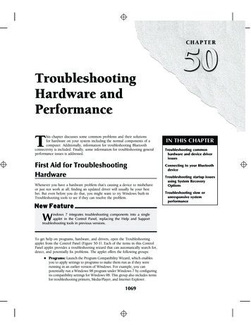
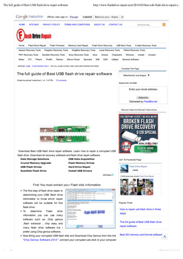
7A. Relay Not ClosingConnect the AC input cord to a live outlet and DC output plug to the battery receptacle. Usingan appropriate multi-meter, set it to measure AC volts on a scale large enough to measure 120VAC. Place the two meter probes across point A (screw head) and B (dual QD terminal) asshown in Figure. 7A. If normal AC voltage is present, the AC input circuit is connectedproperly.Figure 7AFigure 7BFigure 7CAdjust the multi-meter to measure DC voltage and place the test probes at the wire harnessconnector on the electronic charge controller as shown in Figure 7B. The voltage measuredshould be the same as the battery voltage pack. If the correct DC voltage is present, the DCoutput circuit is connected properly. If not, check the connections at the battery receptacle, theplug sense contact and sense wire, the controller wire harness, the diode assembly, and at theammeter.If both the AC and DC voltages are present on the electronic controller and the charger still willnot start then check to make sure the screws holding the relay board assembly to the pottedelectronic board are tight. A loose connection on these screws will prevent the charger fromstarting. With the multi-meter adjusted to measure 120 volts AC, place the test probes acrosspoints A (top screw head) and C (bottom screw head) as shown in Figure 7C. If input linevoltage is not present after the five-second delay time, the electronics have malfunctioned andthe electronic charger controller will have to be replaced. If input line voltage is present, thenthe relay board assembly has failed and will have to be replaced.Bypassing the electronic charge controllerThe electronic charge controller may be bypassed in order to verify that a malfunction existswith the controller. Disconnect the charger’s AC input cord from its outlet and the DC outputplug from the battery receptacle. Find the white wire from the transformer which attaches tothe NO terminal and the black AC input cord wire which attaches to the COM terminal on therelay. Remove these two wires from the relay and connect them directly to each other asshown in Figure 7D and 7E. We suggest that you fabricate a 14-gauge wire, three incheslong, that has 1/4 inch quick disconnect male terminals crimped and soldered onto both ends.www.lesterelectrical.com1035827 A
CAUTION: NEVER ‘ROCK’ OR ‘WALK’ THESE TERMINALS TO GET THEM ON OROFF OF THE RELAYS. USE A ‘DIRECT’ IN/OUT MOTION WHEN INSTALLING ANDREMOVING THESE TERMINALS.The goal is to minimize widening or spreading of the ‘curl’ of the female terminal that reducesthe clamping strength and area of surface contact with the blade in the relay. Use largeneedle-nose pliers or similar tool that you feel comfortably in control of to remove and installthese quick disconnect terminals from the relay blades.Figure 7DFigure 7EThe charger operation may be checked by first connecting the DC output plug to the batteryreceptacle, and then connecting the AC input cord to a live outlet. If the transformer hums andnormal charging current is indicated on the ammeter, the electronic charge controller isdefective and must be replaced.CAUTION: DO NOT CHARGE BATTERIES WITH THE ELECTRONIC CHARGE CONTROLLER BYPASSED. THE CHARGER WILL REMAIN ON AS LONG AS THE AC INPUTCORD IS CONNECTED TO A LIVE OUTLET. SEVERE OVERCHARGING AND EVENTUALDAMAGE TO BATTERIES WILL RESULT.7B. Not Turning OffThe electronic charge controller has a built in maximum timer, which will turn the charger off ifit has run for 16 hours. The actual time may be longer than this if the AC input voltage hasbeen off during part of a charge cycle. Connect the AC input cord to a live outlet, then checkto see if the charger turns on immediately without the normal three to five (3-5) second delaywhen the DC output cord is connected. If the charger turns on instantly, the electronic chargecontroller relay contacts have probably failed closed. This type of malfunction results in thecharger not turning off.CAUTION: DISCONNECT BOTH AC INPUT AND DC OUTPUT CORDS FROM ALLPOWER SOURCES BEFORE YOU PERFORM THIS TEST.www.lesterelectrical.com1135827 A
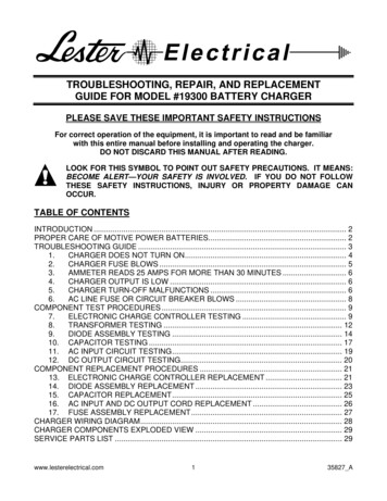
Remove the Phillips screws that retain the cover, and then remove the cover. Remove the twoscrews that hold the controller to the enclosure. Stuck relay contacts may open if jarred, sogently move the controller to access the points as shown in Figures 7F and 7G. With a multimeter set to measure resistance, measure across the relay contacts as shown in Figure 7F. Ifthere is continuity, the contacts have welded closed and the relay board assembly will need tobe replaced. If the meter shows an open circuit, measure the resistance of the relay coil asshown in Figure 7G. Normal resistance reading will be between 2,000 and 3,500 ohms. If themeasured resistance displays an open, low reading, or short circuit, the relay coil has failedand the controller will need to be replaced.Figure 7FFigure 7GIf the relay contacts and relay coil both test OK, a test to verify if the electronic chargecontroller has malfunctioned can be made if a precision digital type DC voltmeter is available.Connect the charger to the battery pack and allow it to charge normally. After the chargeoutput amperage has tapered to its lowest point, measure the battery terminal voltage using aDC voltmeter capable of reading in increments of .001 volts. Continue charging and check thebattery voltage reading every hour. If the battery voltage increases less than .072 volts, or ifthe battery voltage decreases between successive hourly readings, the charger should turn off.If the charger does not turn off, the electronic charge controller has malfunctioned and must bereplaced.8.TRANSFORMER TESTINGFailure of the transformer can be the result of natural aging, premature shorting of adjacent coilturns or overheating damage. The most common cause of transformer overheating andpremature burnout is the result of misuse, connecting the charger to a battery system of lowervoltage than specified on the charger. Darkening of all the transformer secondary coilwindings is an indication of possible overheating damage. A low or complete lack of outputwould be observed on the ammeter; however, the transformer may hum or the AC line fuse orcircuit breaker may blow when the charger is turned on.The purpose of this test is to confirm the AC output voltage of the transformer. Please read,review, and understand this entire testing procedure before you perform this test.www.lesterelectrical.com1235827 A
CAUTION: DISCONNECT BOTH AC INPUT AND DC OUTPUT CORDS FROM ALLPOWER SOURCES BEFORE YOU PERFORM THIS TEST.Remove the Phillips screws that retain the cover, and then remove the cover. Locate thetransformer output leads that attach to the rectifier/diode assembly at the rear of the case asshown in Figure 8, then remove the 11/32 nuts that retain these leads. Carefully repositionthese leads so that they are at least 1/4 inch away from any objects near them as shown inFigure 8.Figure 8DANGER: HAZARD OF ELECTRICAL SHOCK. ONLY QUALIFIED PERSONNEL WHOARE KNOWLEDGABLE IN ELECTRICAL SAFETY PRECAUTIONS ARE TO TESTEQUIPMENT WHILE ENERGIZED!A
TROUBLESHOOTING, REPAIR, AND REPLACEMENT GUIDE FOR MODEL #19300 BATTERY CHARGER PLEASE SAVE THESE IMPORTANT SAFETY INSTRUCTIONS For correct operation of the equipment, it is important to read and be familiar with this entire manual before installing and operati